
MDA ORIENTED COMPUTATION INDEPENDENT MODELING
OF THE PROBLEM DOMAIN
Janis Osis, Erika Asnina and Andrejs Grave
Faculty of Computer Science and Information Technology, Institute of Applied Computer Systems
Riga Technical University, Latvia
Keywords: MDA, problem domain, topological functioning modeling, use case, eclipse.
Abstract: The proposed approach called Topological Functioning Modeling for Model Driven Architecture
(TFMfMDA) uses formal mathematical foundations of Topological Functioning Model (TFM). It
introduces the main feature of MDA – Separation of Concerns by formal analysis of a business system,
enables mapping to functional requirements and missing requirements checking in conformity with the
problem domain TFM model. By using a goal-based method, a use case model of the planned application is
defined and use cases are classified. Graph transformation from the TFM to a conceptual class diagram
enables the definition between domain concepts and their relations to be established. The paper also
suggests a concept of a tool for the TFMfMDA, which is realized as an Eclipse plug-in.
1 INTRODUCTION
The main idea of the given work is to introduce
more formalism into the problem domain modeling
within OMG Model Driven Architecture (MDA)
(Miller and Mukerji, 2003) in the field of object
oriented software development. For that purpose,
formalism of a Topological Functioning Model
(TFM) is used (Osis, 2006). The TFM holistically
represents complete functionality of the system from
computation-independent viewpoint. It considers
problem domain information separate from the
application domain information captured in
requirements and thus satisfies the main feature of
MDA – Separation of Concerns
, therefore TFM is an
expressive and powerful instrument for a clear
presentation and formal analysis of system
functioning and the environment the system works
within.
This paper is organized as follows. Section 2
describes key principles and suggested solutions for
a computation independent modeling as well as their
weaknesses in the object oriented analysis (OOA)
within the MDA. Section 3 discusses a developed
approach, i.e. Topological Functioning Modeling for
Model Driven Architecture (TFMfMDA). Section 4
describes the concept of a tool that partially
automates it. Conclusions establish further directions
into the research of Computation Independent Model
(CIM).
2 CIM CONSTRUCTING WITHIN
THE MDA
The MDA states that the CIM usually includes
several distinct models that describe system
requirements, business processes and objects;
environment the system will work within, etc. OOA
is a semiformal specification technique that contains
use case modeling, class modeling, and dynamic
modeling. Use cases are rather weak formalized
approach that fragmentary describes the application
domain. Their usage is not systematic in comparison
with systematic approaches that enable identification
of all system requirements. Fig. 1 shows several
existing ways of creating use case models and
establishment of concepts and relations among them.
One way is to apply assisting questions (Jacobson et
al., 1992), (Leffingwell et al., 2003), categories of
concepts and concept relations (Larman, 2005) or
goals (Cockburn), (Leffingwell et al., 2003) in order
to identify use cases and concepts from the
description of the system (in a form of an informal
description, expert interviewing, etc.). Another way
is drafting a system requirements specification using
some requirement gathering technique. Later these
66
Osis J., Asnina E. and Grave A. (2007).
MDA ORIENTED COMPUTATION INDEPENDENT MODELING OF THE PROBLEM DOMAIN.
In Proceedings of the Second International Conference on Evaluation of Novel Approaches to Software Engineering , pages 66-71
DOI: 10.5220/0002584500660071
Copyright
c
SciTePress
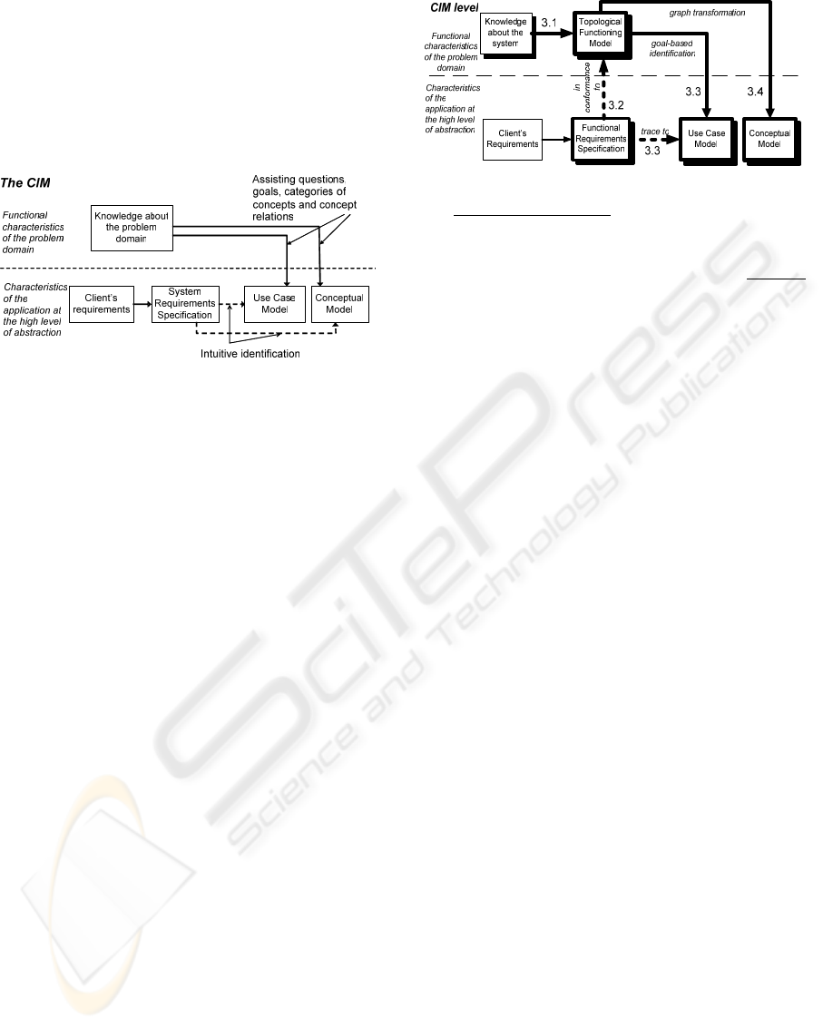
requirements are used for use case identification and
conceptual model creation. The most complete way
is use case and concept identification having
knowledge of the problem domain as well as the
system requirements specification (Arlow and
Neustadt, 2005). All these ways use some mixture of
information from both sides of the dashed line (fig.
1).
Figure 1: The current state of CIM creation in the OOA.
Use case modeling starts with some initial
estimate (a tentative idea) about where the system
boundary lies. As an example we can mention the
Unified Process (Arlow and Neustadt, 2005), where
use cases are driven by system requirements, the
B.O.O.M. (Podeswa, 2005), which is IT project
driven, and Alistair Cockburn's approach
(Cockburn). Use cases’ fragmentary nature does not
give any answer to questions about identifying all of
system’s use cases, conflicts among the use cases,
gaps in the system’s requirements, how changes can
affect behavior that other use cases describe (Ferg,
2003). We consider that problem domain modeling
and understanding to be the primary stage in the
software development, especially in case of
embedded and complex business systems, whose
failure can lead to huge losses. This means that use
cases must be applied as a part of a technique,
whose first activity is a construction of a well-
defined problem domain model. Such an approach is
TFMfMDA which is discussed in this paper. This
research can be considered as a step towards the
MDA completeness.
3 TOPOLOGICAL
FUNCTIONING MODELING
FOR MDA
The TFMfMDA is based on the formalism of
Topological Functioning Model and uses some
capabilities of universal category logic (Asnina,
2006), (Asnina, 2006, 93-104), (Osis, 2006).
Figure 2: CIM creation with the TFMfMDA in the OOA
with Separation of Concerns.
The main steps of the TFMfMDA are illustrated
by bold lines in Fig. 2. There are two separate
branches at the beginning of the problem analysis:
analysis at the (business or enterprise) system level,
and analysis at the application system level. Having
knowledge about a complex system that operates in
the real world, a TFM of this system can be
composed. The main idea is that the functionality
determines the structure of the planned system. This
means that the TFM of the system is controlled and
can be partially changed by functional requirements.
Then TFM’s functional features are associated to
business goals of the system; this provides business
use cases as well as system use cases identification
according to the problem domain realities.
Moreover, after those activities functional
requirements are not only in conformity with the
business system functionality but also can be
traceable to the system use case model. Problem
domain concepts are selected and described in UML
Class Diagram.
Step 1: Topological Functioning Model
Construction. The TFM has a solid mathematical
base. It is represented in a form of a topological
space (X,
Θ
), where X is a finite set of functional
features of the system under consideration, and
Θ
is
topology that satisfies axioms of topological
structures and is represented in a form of a directed
graph. The necessary condition for construction of a
topological space is a meaningful and exhaustive
verbal, graphical, or mathematical system
description. The adequacy of a model describing the
functioning of some concrete system can be
achieved by analyzing mathematical properties of
such abstract object (Osis, 2006). TFM has
topological (connectedness, closure, neighborhood,
and continuous mapping) and functional (cause-
effect relations, cycle structure, and inputs and
outputs) characteristics. It is acknowledged that
every business and technical system is a subsystem
of the environment.
MDA ORIENTED COMPUTATION INDEPENDENT MODELING OF THE PROBLEM DOMAIN
67
2425 23
11
22
20
21
16
19
15
18
13
14
12
9
7
8
6
1 2 3 4 5
10
17
11
22
20
21 16
19
15
18
13
14
12
9
7
8
6
1 2 3 4 5
10
17
a)
b)
26
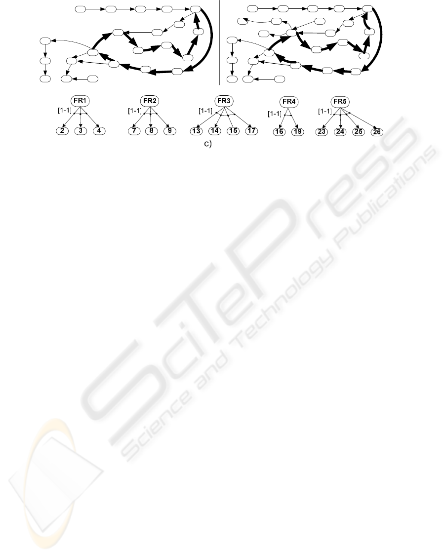
Figure 3: Topological space of the library functioning (a), the modified topological space of the library functioning (b), and
requirement mappings onto the functional features (c).
Steps of the TFM construction for problem
domain modeling in a business system context are as
follows: a) Definition of physical or business
functional characteristics (inner and external
objects, functional features) by means of noun and
verb analysis in the informal problem description; b)
Introduction of topology, i.e. establishing cause-
effect relations between functional features. These
relations are represented as arcs of a digraph that are
oriented from a cause vertex to an effect vertex; and
c) Separation of the topological functioning model.
Cause-effect relations form causal chains that
sometimes are functioning cycles. All the cycles and
subcycles should be carefully analyzed in order to
completely identify existing functionality of the
system. The main cycle (cycles) of system
functioning (i.e. functionality that is vitally
necessary for system’s life) must be found and
analyzed before starting further analysis. In case of
studying a complex system, a TFM can be separated
into a series of subsystems according to identified
cycles.
The result of this activity can be represented like
the one in Fig.3a that illustrates a TFM for a
fragment of library (business) system functioning.
The identified inner objects are a librarian, a book
copy, a reader account, a reader card, a request for a
book, a fine, a loan term, a statement of utilization,
book fund. The identified functional features should
be represented in the form of <functional feature,
[{precondition},] the responsible entity,
subordination (“in” is inner, “ex” is external)>, e.g.
“1: Arriving of a person, person, ex” or “2: Creating
of a reader account, {unregistered person}, librarian,
in”. All system functionality– the set X got by the
closuring operation (Osis, 2006) is X= {2, 3, 4, 5, 6,
7, 8, 9, 10, 11, 12, 13, 14, 15, 16, 17, 19, 20, 21}.
The main functional cycle is defined by an expert,
and includes functional features “17-8-9-10-11-5-
12-13-14-15-17” (bold lines in Fig. 3a).
Step 2: Functional Requirement Conformity to
the TFM. It is the verification that functional
requirement (hereafter requirements) are in
conformity with the constructed TFM. Functional
features specify functionality that exists in the
problem domain. Requirements specify functionality
that must exist in the application. Thus, requirements
can be mapped onto functional features of a TFM.
Mappings are described with arrow predicates ⎯
constructs borrowed from the universal categorical
logic for computer science that is explored in details
in (Diskin et al., 2000).
Within the TFMfMDA, five types of mappings
and corresponding arrow predicates are defined:
one-to-one for a complete specification of a
functional feature, many-to-one for an overlapping
or non-overlapping specification of a functional
feature, one-to-many for an incomplete or complete
specification of a functional feature set, one-to-zero
for a new or undefined functionality specification
(possible changes in functioning must be defined),
and zero-to-one
indicates missed requirements.
Thus, it is mandatory to make a decision about
implementation of the discovered functionality
together with the client. Results of this activity are
both checked and conformed functional
requirements and TFM, which describes needed
system functionality and the environment it operates
within.
Let us assume that five functional requirements
are drafted: FR1, FR2, FR3, FR4, and FR5. The new
functionality introduced by FR5 can be described by
new identified objects (the system, a wait list and
ENASE 2007 - International Conference on Evaluation on Novel Approaches to Software Engineering
68

SMS), and the following functional features – 23,
24, 25, 26. As a result existing cause-effect relations
are rechecked and the set X = {2, 3, 4, 5, 6, 7, 8, 9,
10, 11, 12, 13, 14, 15, 16, 17, 19, 20, 21, 23, 24, 25,
26}. The resulting model is represented in Fig. 3b.
The final mappings of requirements onto the
functional features are illustrated in Fig. 3c.
Step 3: Use Case Model Construction. Transition
from an initial problem domain model to a CIM
“output” model, i.e. a use case model, goes as
follows: 1) Identification of business users (actors
and workers) and their goals. Actors are external
entities that establish business goals. In the TFM,
they are represented as external objects responsible
for functional feature execution. Workers are
system’s inner entities (humans, roles, etc.), who
either establish system goals or implement them and
business goals (OMG, 1997). Identification of goals
is identification of the set of functional features
necessary for the satisfaction of the goal; 2)
Identification and refinement of system’s use cases
that includes discovering functional features
specified by requirements that are needed to achieve
a business goal. It enables formal identification of a
use case model from the TFM. An executor of the
goal is transformed into an (UML) actor. Identified
use cases can be represented in an UML activity
diagram by transforming functional features into
activities, and cause-effect relations into control
flows; 3) Use case prioritizing is defined in
conformity with the main functional cycle (critical,
important, useful).
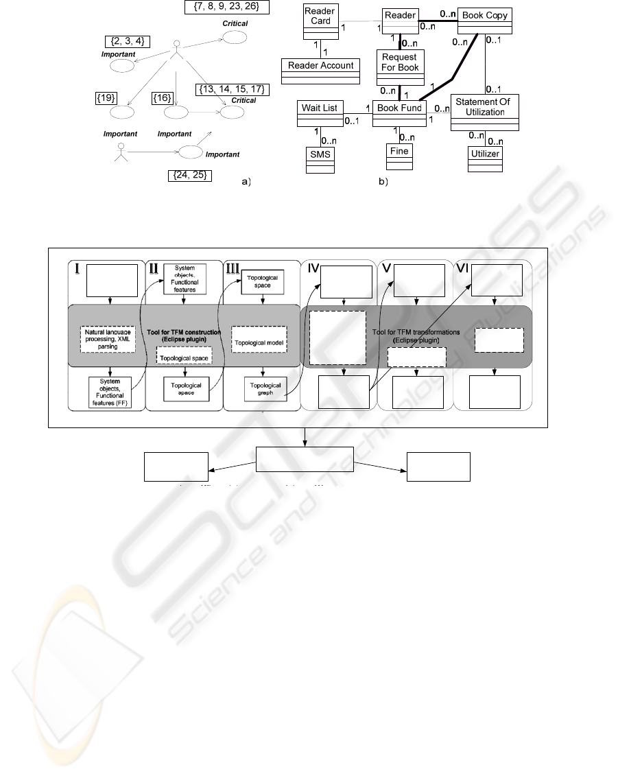
In our example, actors are a person, a reader, and
a utilizer. Workers are a librarian and the system
itself. The resulting use-case model, where workers
are transformed into actors, goal names into use case
names, functional features into steps of the
corresponding use case is shown in Fig. 4a.
Step 4: Obtaining a Concept Diagram. The last
step is identification of a conceptual class model.
After Step 3, the TFM shows functionality that must
be implemented, and includes all concepts that are
necessary for proper functioning.
In order to obtain a conceptual class model each
TFM functional feature is detailed to the level where
it only uses one type objects. After that, this model
must be transformed one-to-one into a problem
domain object graph, and then vertices with the
same type of objects must be merged keeping all
relations with other graph vertices. As a result, a
conceptual class graph with indirect associations is
defined. Concepts used in the main functionality are
necessary in all cases. Such transformation also
indicates possible inheritance relations, and use case
interfaces.
In our example, the step of the TFM refinement is
skipped. Fig. 4b reflects the TFM after the gluing of
all graph vertices with the same object types. This
reflects the idea proposed in (Osis, 2004), (Osis,
2006) that the holistic domain representation by
means of the TFM allows identifying of all
necessary domain concepts, and, even, allows to
define their necessity for a successful
implementation of the system.
4 AUTOMATION OF THE
TFMFMDA
The TFMfMDA uses a complex graph-based
constructs that require additional efforts. The main
purpose of a tool for the TFMfMDA is the model
management, i.e. model verification, traceability
handling, step automation, etc. This section
discusses the concept of the tool that is approved to
be realized at Riga Technical University.
The tool supports client-server architecture. The
server keeps information about models; the client
part enables the connection with the server and the
use of the kept information. It is implemented as an
Eclipse plug-in (Eclipse.org). Eclipse is an open
development platform that consists of different
components, which helps in developing Integrated
Development Environments (IDEs).
For the TFMfMDA tool realization the following
Eclipse components were used: Workbench UI, Help
system, and Plug-in Development Environment
(PDE). The Workbench UI is responsible for plug-in
integration with Eclipse User Interface (UI). It
defines extension points, by using which a plug-in
can communicate with the Eclipse UI. Help System
provides complete integration of help information
into the Eclipse help system. PDE is the
environment that enables automation of activities
related to the plug-in development.
The tool allows working with textual information
(an informal description, a functional requirements
description), and graph-based constructs (a
topological functioning model, a conceptual class
model, a use case model).
MDA ORIENTED COMPUTATION INDEPENDENT MODELING OF THE PROBLEM DOMAIN
69
Register a reader
Close a fine
Check out a book
Librarian
Imp os e a fi ne
System
Return a book
<<extend> >
Inform of available book
<<extend> >
Figure 4: The use case model (a); and the initial conceptual model (b).
System
description
Topological
model,
Functional
requirements
Topological
Model, Goals
Topological
Model
Use case
Model
Topological
Model
Conceptual
class model
Verification of
functional
requirements,
enhancing of
Topological
model
Use case model
verification
Verification of
conceptual
class model
Export XMI Documents
Use case
model
UML class
diagram
Verification of
Verification of
Figure 5: The scheme of the tool supporting the TFMfMDA.
All changes are automatically propagated to the
related models. The scheme of the tool activities is
illustrated in Fig. 5. It describes the considered
TFMfMDA steps. The first three steps reflect TFM
construction, the step IV reflects functional
requirement mapping and TFM enhancing, the step
V illustrates use case model creation, and the step VI
shows the process of getting the conceptual class
diagram. By now realized parts of the tools include
the first three steps. The steps IV, V and VI are still
under research.
The interesting part is the realization of the work
with an informal description. The informal text is
handled on the server side for several reasons. They
are knowledge base using, the multi-user
environment, and “learning” possibilities of the tool.
The server program supports detection of nouns,
noun phrases, and verbs. The detected information is
sent to the client side in XML file form, where it is
highlighted to the user in different ways (different
colors, fonts, etc.). The tool provides convenient
interface for handling this information and creation
of functional features. The topology introduced
between functional features is realized as a mix of
their graphical and textual representation. The tool
offers the user to join, split up and define cause-
effect relations between functional features using a
tabular representation, but the result is also
represented in the form of graphs.
The TFMfMDA tool provides a separate editor
for each step. Each editor has relevant views that
represent actual information. All automated steps
that need user participation are realized as wizards
that open corresponding editors. By now, there are
three wizards constructed in the tool. The first
wizard creates a system description file with the
detected nouns, noun phrases and verbs by the
Natural Language Processing Server (NLPS). The
second one creates a topological space. And the third
one creates a TFM.
ENASE 2007 - International Conference on Evaluation on Novel Approaches to Software Engineering
70

5 CONCLUSIONS
The TFMfMDA application has the following
advantages. First, careful cycle analysis can help to
identify all (possible at that moment) functional and
causal relations between objects in complex business
systems. Use case implementation priorities can be
ordered not only in accordance with the client's
wishes, but in accordance with the functioning
cycles. It makes it possible to take a decision about
functional change acceptability before their
realization in the application, and helps to check
functional requirement completeness. Second, it
solves some use case limitations in information
capturing, thinking limitation and completeness
checking, provides use case completeness, avoids
conflicts among use cases, and shows their effect on
each other. Besides that it does not limit the use of
any requirement gathering techniques.
The tool partially automates TFMfMDA steps
described above. But this approach still requires
human participation. Therefore, the further research
is related to the TFMfMDA enhancing with the
capabilities of natural language handling in order to
make it possible to automate more steps of this
approach and to decrease human participation in
decision making.
REFERENCES
Miller, J., Mukerji, J. (eds): OMG: MDA Guide Version
1.0.1 http://www.omg.org/docs/omg/03-06-01.pdf
(2003)
Osis, J.: Formal computation independent model within
the MDA life cycle. In: International Transactions on
Systems Science and Applications, Vol. 1, Nr. 2.
Xiaglow Institute Ltd, Glasgow, UK (2006) 159-166
Jacobson, I., Christerson, M., Jonsson, P.: Object-Oriented
Software Engineering: A Use Case Driven Approach.
Addison-Wesley (1992)
Leffingwell, D., Widrig, D.: Managing Software
Requirements: a use case approach. 2nd ed. Addison-
Wesley (2003)
Larman, Cr.: Applying UML and Patterns: An
Introduction to Object-Oriented Analysis and Design
and Iterative Development. 3rd ed. Prentice Hall PTR
(2005)
Cockburn, A.: Structuring Use Cases with Goals.
http://alistair.cockburn.us/crystal/ articles/sucwg/
structuringucwithgoals.htm
Arlow, J., Neustadt, I.: UML2 and the Unified Process:
Practical Object-Oriented Analysis and Design.
Addison-Wesley, Pearson Education (2005).
Podeswa, H.: UML for the IT Business Analyst: A
practical Guide to Object-Oriented Requirements
Gathering. Boston, Thomson Course Technology PTR
(2005).
Ferg, S.: What’s Wrong with Use Cases?
http://www.ferg.org/papers/ferg--whats_wrong_with_
use_cases.html (2003)
Asnina, E.: Formalization of Problem Domain Modeling
within Model Driven Architecture. PhD thesis, Riga
Technical University, RTU Publishing House, Riga,
Latvia (2006).
Asnina, E.: Formalization Aspects of Problem Domain
Modeling within Model Driven Architecture. In:
Databases and Information Systems, 7th International
Baltic Conference on Databases and Information
Systems, Communications, Materials of Doctoral
Consortium. Vilnius: Technika (2006) 93-104.
Diskin, Z., Kadish, B., Piessens, F., Johnson, M.:
Universal Arrow Foundations for Visual Modeling. In:
Proc. Diagramms’2000: 1st Int. Conference on the
theory and application of diagrams. Springer LNAI,
No. 1889 (2000) 345-360
Osis, J.: Software Development with Topological Model
in the Framework of MDA. In: Proceedings of the 9th
CaiSE/IFIP8.1/EUNO International Workshop on
Evaluation of Modeling Methods in Systems Analysis
and Design (EMMSAD’2004) in connection with the
CaiSE’2004, Vol. 1. Riga: RTU (2004) 211 – 220
Eclipse – an open development platform.
http://www.eclipse.org
OMG: Uml extension for business modeling. Version 1.1.
http://umlcenter.visual-paradigm.com/umlresources/
(1997)
MDA ORIENTED COMPUTATION INDEPENDENT MODELING OF THE PROBLEM DOMAIN
71
