
A VOCAL TRACT VISUALISATION TOOL FOR A
COMPUTER-BASED SPEECH TRAINING AID FOR
HEARING-IMPAIRED INDIVIDUALS
Abdulhussain E. Mahdi
Department of Electronic & Computer Engineering, University of Limerick, Limerick, Ireland
Keywords: Speech Production, Vocal Tract Models, Articulatory Training, Linear Prediction Coding.
Abstract: This paper describes a computer-based software prototype tool for visualisation of the vocal-tract, during
speech articulation, by means of a mid-sagittal view of the human head. The vocal tract graphics are
generated by estimating both the area functions and the formant frequencies from the acoustic speech signal.
First, it is assumed that the speech production process is an autoregressive model. Using a linear prediction
analysis, the vocal tract area functions and the first three formants are estimated. The estimated area
functions are then mapped to corresponding mid-sagittal distances and displayed as 2D vocal tract lateral
graphics. The mapping process is based on a simple numerical algorithm and an accurate reference grid
derived from x-rays for the pronunciation of a number English vowels uttered by different speakers. To
compensate for possible errors in the estimated area functions due to variation in vocal tract length between
speakers, the first two sectional distances are determined by the three formants. Experimental results show
high correlation with x-ray data and the PARAFAC analysis. The tool also displays other speech parameters
that are closely related to the production of intelligible speech and hence would be useful as a visual
feedback aid for speech training of hearing–impaired individuals.
1 INTRODUCTION
The process of learning to speak in the case of
people with normal hearing is primarily aided by
auditory feedback. However, for those who suffer
from deafness, learning to speak naturally is a very
difficult process. With limited auditory capability, a
hearing-impaired person often lacks models of
speech targets necessary to produce normal speech.
In an effort to overcome this difficulty, many
attempts have been made to provide a substitute for
the feedback mechanism with visual speech display
devices (Choi, 1982; Bunnell et. Al., 2000; Mashie.
1995). However, without any articulatory correlate,
the benefits of such devices were limited. In order to
produce a natural and intelligible speech, a speaker
needs to know how to use the vocal organs in
regards to correct position of the articulators,
breathing, loudness, rhythm and nasalization
(Eriksson, et. al., 2005) . Hence the availability of
visual information regarding these aspects would
greatly help the hearing-impaired improving their
speaking abilities.
This paper describes a system which visualises a
speaker’s vocal tract by means of mid-sagittal
graphical plots of the human head. The vocal tract
shapes, and other related speech parameters, are
graphically displayed on a PC-monitor using
information extracted directly from the acoustic
speech signal as picked up by a microphone or
loaded from an audio file. To estimate the necessary
parameters, it is assumed that the speech production
process is an autoregressive (AR) model. The vocal
tract area functions, log spectra and the first three
formants are then estimated, by employing a linear
prediction (LP) analysis, and used to construct the
corresponding vocal tract graphics and other
parameters display.
2 SPEECH ANALYSIS MODEL
Speech is the acoustic wave that is radiated from the
vocal system when air is expelled from the lungs and
the resulting flow of air is perturbed by a
constriction somewhere in the vocal tract. This
speech production process can be practically
modelled using the well-known all-pole source-filter
approach, which represents the speech signal in
terms of an AR model (Quatieri, 2002). According
153
E. Mahdi A. (2008).
A VOCAL TRACT VISUALISATION TOOL FOR A COMPUTER-BASED SPEECH TRAINING AID FOR HEARING-IMPAIRED INDIVIDUALS.
In Proceedings of the First International Conference on Bio-inspired Systems and Signal Processing, pages 153-158
DOI: 10.5220/0001057201530158
Copyright
c
SciTePress
to this model, speech is split into a rapidly varying
excitation signal, generated by an impulse train input
or a random noise generator, and a slowly varying
filter representing the vocal tract. Voiced speech is
produced by taking the impulse train as excitation.
In unvoiced segments, the random white noise is
used as the excitation. The output speech is
produced by passing the excitation through the vocal
tract filter. Hence, changes in the vocal tract
configuration, reflected by the filter, produces
corresponding changes in the spectral envelope of
the speech signal. Therefore to estimate the vocal
tract shape form the speech signal, an inverse filter
model has to be used (Miller & Mathews, 1963).
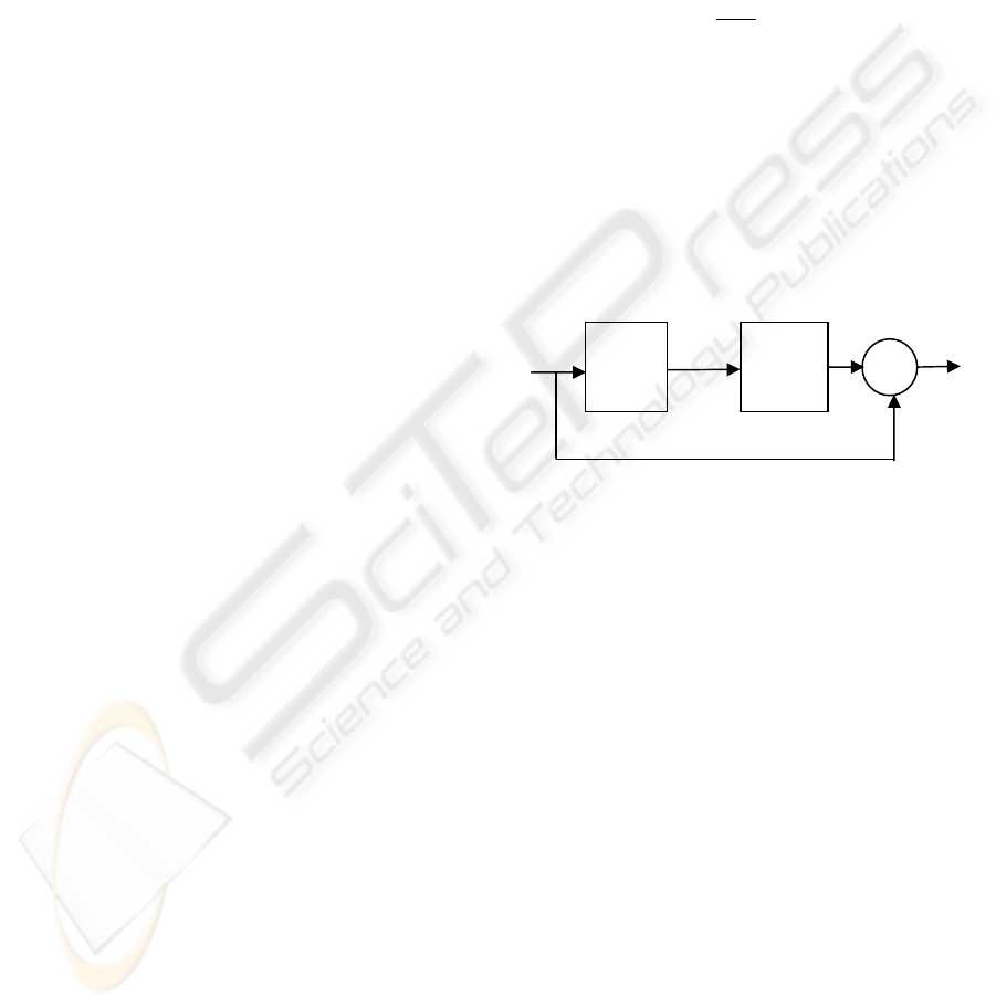
The speech analysis model used in this work is
shown schematically in Figure 1. In this model, it is
assumed that the speech to be analysed is limited to
periodic non-nasalised voiced sounds so that the
filter in Figure 1 is driven by an impulse train. This
means that the filter includes all the contributions
from the glottal wave, the vocal tract and the
radiation impedance at the lips. The inverse filter is
assumed to be a linear filter with only zeros in its
transfer function, and the power spectral envelope of
the speech is assumed to be approximated by poles
only. Accordingly, the transfer function of the
inverse filter can be expressed in terms of z-
transform notation as:
1,)(
0
0
=
∑
=
=
−
azazA
M
i
i
i
(1)
where a
i
are the coefficients of the inverse filter, M
is the order of the filter,
Tj
ez
ω
=
and T is the
sampling period. Here, a
0
affects only the gain of the
system, hence no generality is lost by setting
a
0
= 1.
The objective of this analysis is to obtain a close
representation of the vocal tract. To obtain this
representation, one needs to estimate the coefficients
of the optimal inverse filter described by equation
(1). Wakita (Wakita, 1973) has shown that A(z) is
also an inverse transfer function of a non-uniform
acoustic tube model of the all-pole vocal tract
model. Thus the optimal inverse filter process in the
above speech analysis model can be equivalently
replaced by a filtering process of an acoustic tube of
length l, which is the assumed length of the vocal
tract, divided into arbitrary number, M, of sections
with equal length
Δ
l, provided that:
(a) The continuity conditions for the volume
velocity and sound pressure are satisfied at each
junction between two adjacent sections;
(b) The length of the individual tube sections,
Δ
l, are
kept short compared to the wavelength at the
highest frequency of interest;
(c) No losses are accounted for, and
(d) It should also be noted that the identity of the
filtering process of the above described acoustic
tube to that of the optimum inverse filter is
obtained under the condition
Tjclj
eez
ωω
==
Δ /2
, where c is the velocity of
sound. Consequently, the sampling frequency F
s
=1/T and the number of sections M=l/
Δ
l is
constrained by (Wakita, 1973):
l
cM
F
s
2
=
(2)
Therefore, as long as F
s
is constant, the vocal
tract length, l, is assumed to be fixed here and M,
i.e. number of the sections or the filter’s order,
has to be chosen to satisfy equation (2).
3 MODELLING THE VOCAL
TRACT
The vocal tract can be modelled as an acoustic tube
of varying diameter. If we abstract from the vocal
tract curvature, the acoustic tube can be divided into
cylindrical sections of equal lengths. Depending on
the shape of the acoustic tube, a sound wave
travelling through it will be reflected in a certain
way so that interferences will generate resonances at
certain frequencies. These resonances are called
formants. Their location largely determines the
speech sound that is heard.
It is well known that the linear prediction (LP)
analysis of speech signals is based on an AR speech
production model (Markel & Gray, 1976). It has also
been shown by several researchers that the LP
process is equivalent to the filtering process of a
non-uniform acoustic tube model where the tube is
divided into an arbitrary number of sections of equal
length (Wakita, 1973; Markovic, 1999). Thus, if the
conditions stated at the end of Section 2 are
satisfied, and if the speech signal is pre-emphasis to
compensate for the spectral characteristics of the
glottal excitation source and for the lips radiation
impedance, then estimates of the vocal tract area
functions can be obtained by computing the
Figure 1: The speech analysis model.
Speech
FILTER
1/A(z)
INVERSE
FILTER
A(z)
Error
+
−
∑
Impulse
Train
BIOSIGNALS 2008 - International Conference on Bio-inspired Systems and Signal Processing
154
reflection coefficients at the junctions between
adjacent sections of the equivalent acoustic tube.
This can be done by using an LP model of the
appropriate order and the following relation:
i
i
ii
ii
ii
i
AA
AA
AA
μ
μ
μ
+
−
=⇔
+
−
=
+
+
+
1
1
1
1
1
(3)
where A
i
and A
i+1
are the cross-sectional areas of two
adjacent sections of the non-uniform acoustic tube
indexed in ascending order from the lips to the
glottis, and
μ
i
is the reflection at the junction
between these two sections.
4 SYSTEM DESIGN AND
DESCRIPTION
Using the vocal tract model described in Section 3, a
PC-based prototype system for visualisation of the
human vocal tract shapes and other associated
speech parameters has been designed and developed.
The system uses the PC’s sound card operating with
8 kHz sampling frequency and 16-bit resolution, to
extract the necessary speech parameters directly
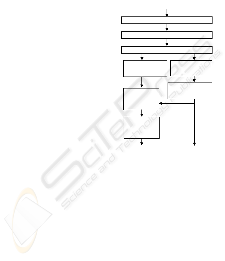
from the acoustic speech waveform. shows The
block diagram given in Figure 2 depicts the
functionality and main processing blocks of the
developed system.
For simplicity, our system uses an initial
assumption that the vocal tract is 17 cm long. As the
PC’s sound card samples the speech at the rate of 8
kHz, thus satisfying equation (2) requires M to be
equal to 8, i.e. the initial use of an acoustic tube with
8 sections. Consequently, an 8
th
order LP analysis
model is employed by the system.
4.1 Estimation of the Area Functions
The speech signal is segmented into 30 ms frames
using a hamming window of an appropriate length.
A pre-emphasis of an approximately 6 dB/octave is
applied to the current frame using an FIR high-pass
filter of the form:
1
9375.0
−
−=
nnn
xxy
(4)
The reflection coefficients are computed by applying
an 8
th
order LP analysis model using an
autocorrelation method that uses LPC uses the
Levinson-Durbin recursive algorithm due to its
simplicity and ease of its implementation within the
chosen computing environment. Equation (3) is then
used to estimate the corresponding vocal tract area
functions as discussed in Section 3. As an example,
Figure 3 (the upper half) shows the normalised area
functions for the English vowel /UH/, as computed
by the system using an 8-section acoustic tube
model. The LP model is also used to obtain the log
spectra, whose peaks are then marked to identify and
estimate the first three formants, as also illustrated in
lower half of Figure 3.
Figure 2: Functional block diagram of the system.
4.2 Mapping to Mid-sagittal Distances
Since the human vocal tract does not resemble an
exact circular tube, there is therefore a need to
modify the above computed area functions such that
they map correctly into mid-sagittal distances of the
vocal tract profiles. Several areas to profile
transformation techniques have been developed
(Heinz & Stevens, 1965). Most such techniques rely
on derivation of suitable application-specific
transformation parameters using complex analysis of
x-ray and cine-fluorograms of various speakers. A
common technique is the αβ model (Heinz &
Stevens, 1965), which is described by:
ii
i
i
iiii
A
ddA
ββ
α
α
/1
)( =⇔=
(5)
where A
i
is the cross-sectional area of a given
section, d
i
is the mid-sagittal distance and α
i
and β
i
are section dependent parameters. In our system, we
Acoustic Speech Signal
Segmentation & Hamming Windowing
Pre-emphasis (High-pass Filter)
LP Analysis (LP Coefficients)
Vocal Tract Areas &
Mid-sagittal
Distance Estimation
Mapping Distances
to Profiles of Vocal
Tract
Estimation of Reflection
Coefficients
Estimation of Log
Spectra
Estimation & Marking of
Formants
2D Mid-Sagittal Vocal
Tract Graphics
X-Y Charts for the
Pitch & Formants
A VOCAL TRACT VISUALISATION TOOL FOR A COMPUTER-BASED SPEECH TRAINING AID FOR
HEARING-IMPAIRED INDIVIDUALS
155
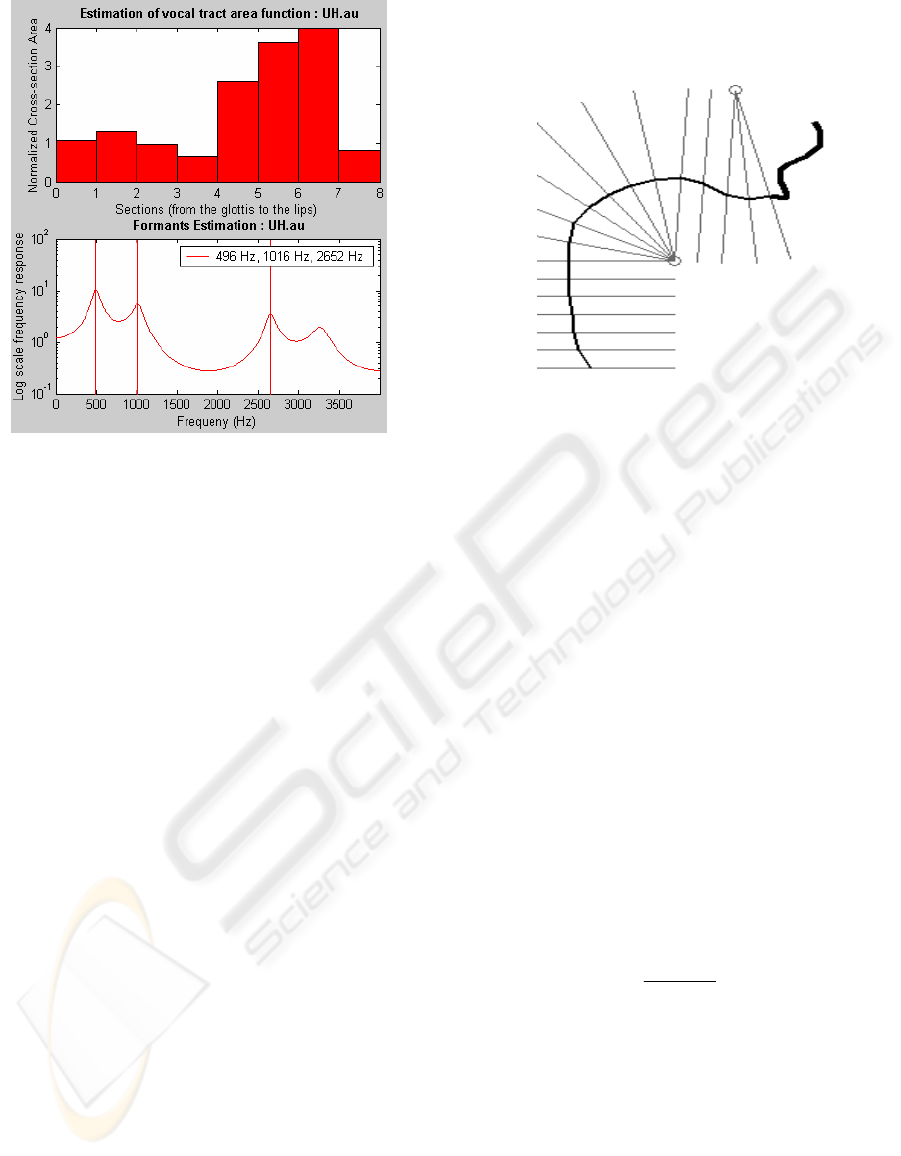
Figure 3: Vocal tract area functions and the first three
corresponding formants for the vowel /UH/.
employ a new method based on the above model to
measure the mid-sagittal distances along the lines of
a semipolar grid (See Figure 4) according to the
following procedure:
(a) The vocal tract was assumed to be divided into
18 equal sections.
(b) In the vocal organs, the shortest path from the
upper to the lower part of each section was
selected.
(c) The upper jaw was assumed to be fixed and the
lower jaw was movable.
(d) A reference grid for the upper jaw based on x-
ray data of the lateral shape of the vocal tract and
on results of the PARAFAC analysis (Harshman,
et. al., 1977) was designed, as shown in Figure 4.
In this grid, straight perpendicular lines were
drawn through the centre of each section, in
accordance with (b) above.
(e) The 8 area functions estimated by the 7th order
LP model were re-sampled and redistributed to
fit the 18-section vocal tract configuration used
in the system.
(f) Based on equation (5), a simple numerical
procedure is used to estimate the values of the
coefficients
α
and
β
that minimize the root mean
squared error between the area functions
estimated in (e) above and those derived from
measurement data obtained from (Harshman, et.
al., 1977) for pseudo-sagittal dimensions of the
tongue position for five speakers each saying ten
English vowels. The estimated area functions are
then interrupted as functions of
α
and
β
, as given
in equation (5), to compute the mid-sagittal
distances.
Figure 4: The reference upper jaw grid used in the system.
As indicated previously, initially the vocal tract
is modelled in our system with an assumption that it
is 17 cm long. It is known, however, that the vocal
tract length for the utterance of various sounds
varies even for a single speaker. In addition, the
male vocal tract is generally slightly longer than 17
cm, while children and females have shorter vocal
tracts (Kirlin, 1978). Hence, the above assumption
may cause an error in the distribution of the area
functions along the assumed vocal tract
configuration. To compensate for this possible
source of error, the first two mid-sagittal distances
have been determined from the three estimated
formants F
1
, F
2
and F
3
as follows (Ladefoged, et. al.,
1978):
421322211
/3 CFFCFFCFCX +
+
+
=
(6)
where X
1
is the mid-sagittal distance between the
lips in cm, C
1
= 0.3×10
-3
, C
2
= −0.343×10
-6
, C
3
=
4.143, C
4
= −2.865. The mid-sagittal distance
between the upper and lower teeth, X
2
, is estimated
by:
2
31
2
XX
X
+
=
(7)
where X
3
is the mid-sagittal distance extracted from
the vocal tract area function that corresponds to
section 3. In addition, the estimated formants have
been used to adjust the rounding degree of the lips
and the height of the jawbone on the designed vocal
tract lateral graphics.
BIOSIGNALS 2008 - International Conference on Bio-inspired Systems and Signal Processing
156

5 RESULTS AND DISCUSSION
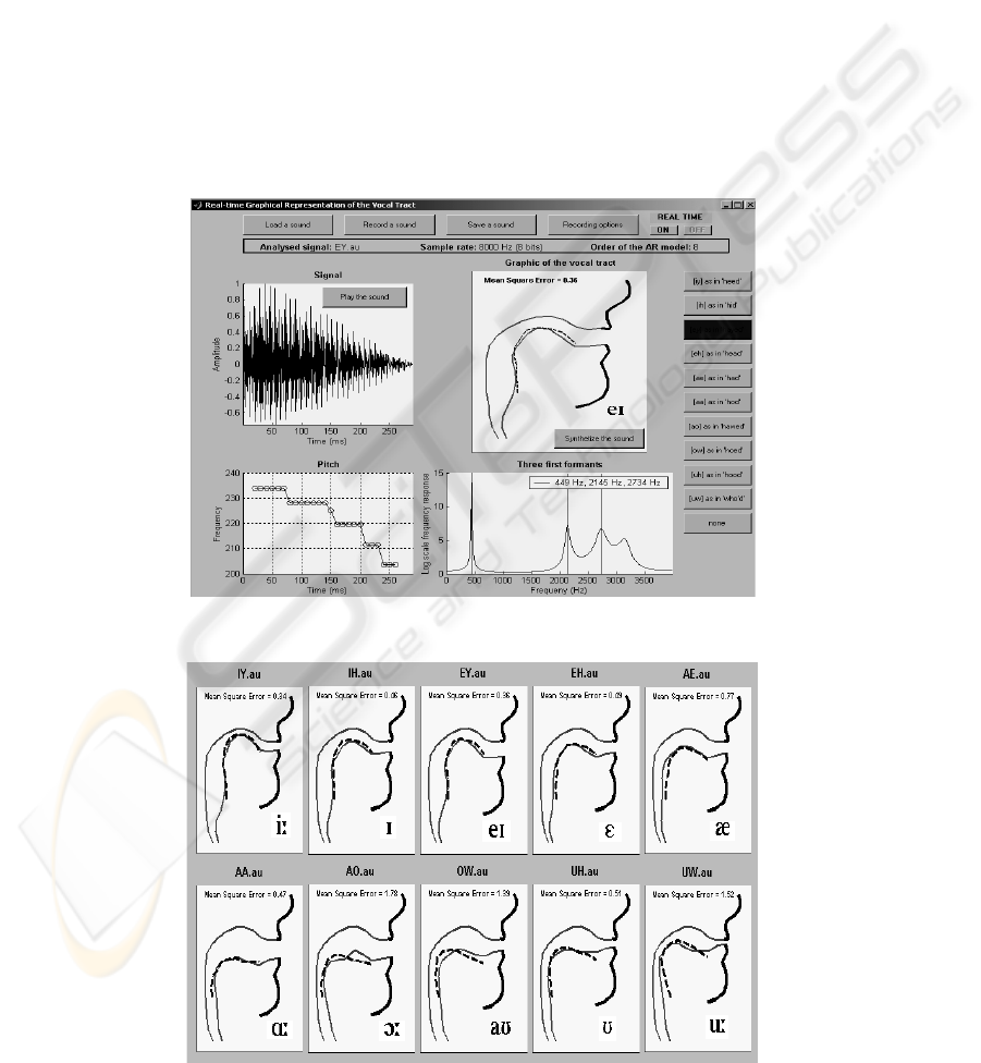
The vocal tract visualisation tool has been designed
to operate with MS Windows-based PC
environment. The multi-display window and other
user’s features of the complete system are shown in
Figure 5. As can be seen, the system’s screen is
divided into four windows for displaying the vocal
tract graphics, the sound intensity, the pitch and the
first three formants of the speech signal. The system
can operate in two main modes: (a) near real-time
mode, whereby the speech signal is picked up by a
microphone connected to the PC sound card (as with
the case shown in Figure 5), and (b) non real-time
mode, whereby the speech signal is either recorded
by the system or read from a stored audio file, and
its features are then displayed. It also allows the
saving of speech/sound signals. For the vowel
articulation, the user can compare the shape of
his/hers vocal tract to a reference trace (shown with
a dashed line in Figure 5) for the correct tongue
position derived from the measurements data
reported in (Miller & Mathews, 1963). The
deviation from the reference trace is given for this
case in the form of a computed mean squared error
(MSE) of all the estimated mid-sagittal distances.
Figure 6 shows the vocal tract profiles for 10
American English vowels, as estimated by the
system (dashed lines represent reference trace for
tongue position). For comparison and evaluation
purposes, the deviations, in terms of MSE values,
from the reference tongue position data adopted
from (Harshman, et. al., 1977) are also indicated. In
general, the obtained results seem to correlate well
with the reference data. They were also found to
correlate well with x-ray data and the PARAFAC
analysis. Referring to the MSE values shown in
Figure 6, the system seems to perform particularly
well in the cases of all the ‘front vowels’, such as
/IY/, /EY/, /IH/, /EH/ and /AE/, with the MSE
increasing as the vowel height decreases. With the
exception of /AA/ and /UH/, the results show
relatively less accurate correlation with the reference
data for the cases of the ‘back vowels’. As vowel
classification into front and back vowels is related to
the position of the tongue elevation towards the front
or the back of the mouth, we believe that the higher
accuracy in the cases of the front vowels is attributed
to the formant-based added adjustments of the lips,
jawbone and front sections of the vocal tract we used
in our approach.
On the other hand, the relative length of the
vowel’s vocalisation seems to affect the accuracy of
the estimated area functions and hence the displayed
vocal tract shape. In specific, the system seems to
give relatively lower accuracy for relatively longer
vowels, such as /AO/, and complex vowels which
involve changes in the configuration of the mouth
during production of the sound, such as /OW/. We
believe this is due to the fact that the system, in its
current design, bases its estimation of the speech
parameters on information extracted from the 2-3
middle frames of the analysed speech waveform.
6 CONCLUSIONS
We have described the process of designing and
development of a computer-based system for the
near real-time and non real-time visualisation of the
vocal tract shape during vowel articulation.
Compared to other similar systems, our system uses
a new approach for estimating the vocal tract mid-
sagittal distances based on both the area functions
and the first three formants as extracted from the
acoustic speech signal. It also utilises a novel and
simple technique for mapping the extracted
information to corresponding mid-sagittal distances
on the displayed graphics. The system is also
capable of displaying the sound intensity, the pitch
and the first three formants of the uttered speech. It
extracts the required parameters directly from the
acoustic speech signal using an AR speech
production model and LP analysis. Reported
preliminary experimental results have shown that in
general the system is able to reproduce well the
shapes of the vocal tract, with real-time sensation,
for vowel articulation. Work is well underway to
optimise the algorithm used for extraction of the
required acoustics information and the mapping
technique, such that dynamic descriptions of the
vocal tract configuration for long and complex
vowels, as well as vowel-consonant and consonant-
vowel are obtained. Enhancement of the system’s
real-time capability and features, and facilitation of
an integrated speech training aid for the hearing-
impaired are also being investigated.
REFERENCES
Choi, C.D., 1982. A Review on Development of Visual
speech Display Devices for Hearing Impaired Children.
Commun. Disorders, 5, 38-44.
Bunnell, H.T., Yarrington, D. M. & Polokoff, 2000.
STAR: articulation training for young children. In Intl.
Conf. on Spoken Language Processing
(INTERSPEECH 2000), 4, 85-88.
Mashie, J.J., 1995. Use of sensory aids for teaching speech
to children who are deaf. In Spens , K-E. and Plant, G.
A VOCAL TRACT VISUALISATION TOOL FOR A COMPUTER-BASED SPEECH TRAINING AID FOR
HEARING-IMPAIRED INDIVIDUALS
157
(Eds.), Profound Deafness and Speech
Communication, 461-491, Whurr Publishers Ltd.
Eriksson, E., Balter,, O., Engwall, O., Oster, A-M. &
Sidenbladh-Kjellstrom, H., 2005. Design
recommendations for a computer-based speech
training system based on end-user interviews. In.
SPECOM 2005, 10
th
Intl. Conf. on Speech and
Computer, 483-486.
Quatieri, T.E., 2002. Discrete-time Speech signal
Processing, Principles and Practice, Prentice Hall.
NJ, USA.
Miller, J.E. & Mathews, M.V., 1963. Investigation of the
glottal waveshape by automatic inverse filtering. J.
Acoust. Soc. Am., 35, 1876-1884.
Wakita, H., 1973. Direct Estimation of the Vocal Tract
Shape by Inverse Filtering of Acoustic Speech
Waveforms. IEEE Trans. on Audio and
Electroacoustics, AU-21, 417-427.
Markel, J. & Gray, A., 1976. Linear Prediction of Speech,
Springer-Verlag. New York, USA.
Markovic, M., 1999. On determining heuristically decision
threshold in robust AR speech model identification
procedure based on quadratic classifier. In ISSPA’99,
5
th
Intl. Symp. Sognal Process. And its Applications.
131-134.
Heinz, J.M. & Stevens, K.N., 1965. On the relations
between lateral cineradiographs area functions and
acoustic spectra of the speech. In 5th Int. Congress of
Acoustics. Paper A44.
Harshman, R., Ladefoged, P. & Goldstein, L., 1977.
Factor analysis of tongue shapes. J. Acoustics Soc.
Am., 62, 693-706.
Kirlin, R.L., 1978. A posteriori estimation of vocal tract
length. IEEE Trans. Acoust., Speech, Signal Process.,
ASSP—26, 571-574.
Ladefoged, P., Harshman, R., Goldstein, L., & L. Rice,
1978. Generating vocal tract shapes from formants
frequencies. J. Acoustics Soc. Am., 64, 1027-1035.
Figure 5: System’s multi-pane screen display and user’s extracted features.
Figure 6: Vocal tract profiles for 10 American English vowels as estimated by the system (dashed lines represent reference
traces for tongue positions).
BIOSIGNALS 2008 - International Conference on Bio-inspired Systems and Signal Processing
158
