
UNDERWATER PHOTOGRAMMETRY FOR ARCHAEOLOGY
The VENUS Project Framework
P. Drap
1
, D. Scaradozzi
2
, P. Gambogi
3
and F. Gauch
4
1
LSIS Laboratoire des Sciences de l'Information et des Systèmes UMR CNRS 6168, France
2
Interuniversity Centre for Integrated Systems for the Marine Environment (ISME) c/o DIST
Università di Genova, Italy
3
SBAT Soprintendanza per i Beni Archaeologici della Toscana, Firenze, Italy
4
COMEX, COmpagnie Maritime d’EXpertise Marseille, France
Keywords: Underwater, archaeology, photogrammetry.
Abstract: This article describes on-going developments of the VENUS European Project (Virtual ExploratioN of
Underwater Sites, http://www.venus-project.eu) concerning the first mission to sea in Pianosa Island, Italy
in October 2006. The VENUS project aims at providing scientific methodologies and technological tools
for the virtual exploration of deep underwater archaeological sites. The VENUS project will improve the
accessibility of underwater sites by generating thorough and exhaustive 3D records for virtual exploration.
In this paper we focus on the underwater photogrammetric approach used to survey the archaeological site
of Pianosa. After a brief presentation of the archaeological context we shall see the calibration process in
such a context. The next part of this paper is dedicated to the survey: it is divided into two parts: a DTM of
the site (combining acoustic bathymetry and photogrammetry) and a specific artefact plotting dedicated to
the amphorae present on the site.
1 INTRODUCTION
The VENUS project is funded by European Com-
mission, Information Society Technologies (IST)
program of the 6th FP for RTD. It aims at providing
scientific methodologies and technological tools for
the virtual exploration of deep underwater archaeo-
logical sites (Chapman et al., 2006).
Underwater archaeological sites, for example
shipwrecks, offer extraordinary opportunities for
archaeologists due to factors such as darkness, low
temperatures and a low oxygen rate which are fa-
vorable to preservation. On the other hand, these
sites cannot be experienced first hand and today are
continuously jeopardized by activities such as deep
trawling that destroy their surface layer.
The VENUS project will improve the accessibil-
ity of underwater sites by generating thorough and
exhaustive 3D records for virtual exploration.
The project team plans to survey shipwrecks at
various depths and to explore advanced methods and
techniques of data acquisition through autonomous
or remotely operated unmanned vehicles with inno-
vative sonar and photogrammetry equipment. Re-
search will also cover aspects such as data process-
ing and storage, plotting of archaeological artifacts
and information system management. This work will
result in a series of best practices and procedures for
collecting and storing data.
Further, VENUS will develop virtual reality and
augmented reality tools for the visualization of an
immersive interaction with a digital model of an
underwater site. The model will be made accessible
online, both as an example of digital preservation
and for demonstrating new facilities of exploration
in a safe, cost-effective and pedagogical environ-
ment. The virtual underwater site will provide ar-
chaeologists with an improved insight into the data
and the general public with simulated dives to the
site.
The VENUS consortium, composed of eleven
partners, is pooling expertise in various disciplines:
485
Drap P., Scaradozzi D., Gambogi P. and Gauch F. (2008).
UNDERWATER PHOTOGRAMMETRY FOR ARCHAEOLOGY - The VENUS Project Framework.
In Proceedings of the Third International Conference on Computer Graphics Theory and Applications, pages 485-491
DOI: 10.5220/0001100504850491
Copyright
c
SciTePress

archaeology and underwater exploration, knowledge
representation and photogrammetry, virtual reality
and digital data preservation.
This paper focuses on the first experimentation
in Pianosa Island, Tuscany, Italy.
The document is structured as follows. A short
description of the archaeological context, then the
next section explains the survey method: calibration,
collecting photographs using ROV and divers, pho-
tographs orientation and a particular way to measure
amphorae with photogrammetry using archaeologi-
cal knowledge. A section shows 3D results in
VRML and finally we present the future planned
work. .
2 THE UNDERWATER
ARCHAEOLOGICAL SITE OF
PIANOSA ISLAND
The underwater archaeological site of Pianosa,
discovered in 1989 by volunteer divers (Giuseppe
Adriani, Paolo Vaccari), is located at a depth of 35
m, close to the Scoglio della Scola, in front of the
east coast of the island. The site is characterized by
the presence of about one hundred amphorae of
different origin and epoch. The various amphorae
range from Dressel 1A (1st century B.C.) to Beltran
2 B and Dressel 20 , up to African models (3rd cen-
tury A. D.) The site has been surveyed in 2001 by
the Nucleo Operativo Subacqueo (MIBAC-SBAT)
divers. This survey, carried out by the SBAT,
proved that the site had remained untouched. And it
was necessary to start a first test of excavation to
know the exact nature of the archaeological site: this
was one of the aims that the October 2006 underwa-
ter mission has reached.
The remarkable depth allows diving and the site
was chosen to make survey using both robotic
equipment and divers.
The experimental activity, under the supervision
of the archaeological team of MIBAC-SBAT, has
been carried out by CNRS for the photogrammetric
survey, ISME with its own ROV equipped with
camera from COMEX, and its georeferentiation and
positioning system.
The site had to be cleaned before surveying,
mainly because of the presence of dead posidonia.
This first operation was made in September 2006 by
SBAT including specialists from CH conservation:
Roberto Bonaiuti and Emiliano Africano.
3 PHOTOGRAMMETRIC
SURVEY IN PIANOSA
The survey is done merging several kinds of infor-
mation: bathymetry, DTM from photogrammetry,
artefacts measure with photogrammetry and theo-
retical model of artefact objects. The entire survey is
stored in a relational database and the geometry is
exported toward tools for Virtual Reality (see fig. 1).
This approach will allow archaeologists to see the
entire site, using immersive VR technologies, with-
out diving.(Drap et al., 2005), (Long, 1996).
3.1 Two Different Ways for Data
Capture
The photogrammetric survey in Pianosa is made by
a set of photographs with the right overlap (around
60%). The geometry is very similar to the technique
used in aerial photogrammetry; the main difference
is the distance to the seabed and the immersion in
water.
As we are sure that the seabed is more or less
flat, we can use a set of photographs with vertical
axis to make the survey.
The photographs are taken by strips with 60%
overlap for the consecutive photographs in a strip
and 20% overlap from one strip to another.
This first mission in Pianosa was an opportunity
to test and improve several ways to perform this
survey. As this site is 35m deep, we can use both a
survey with divers (CNRS partner), and start a sur-
vey by ROV, managed by ISME.(Conte et al.,
2006).
The diver has a Nikon™ D70 digital camera
with a 14 mm lens from Sigma™ and two flashes
Subtronic™. The digital camera was embedded in
Subal™ housing with a hemispherical glass.
COMEX brought its digital camera equipped for
connection to the ROV: a Nikon DH2, a 14 mm lens
from Sigma™ and two flashes Nikon™, SB800.
The housing and connector was made by COMEX
with a flat glass. (See fig.2)
A zone to be surveyed has been determined by
the team and equipped with 4 scale bar (2m) and a
set of 15 makers (cement block 15x15x10cm) in
order to define a network for a better ROV guid-
ance.
GRAPP 2008 - International Conference on Computer Graphics Theory and Applications
486
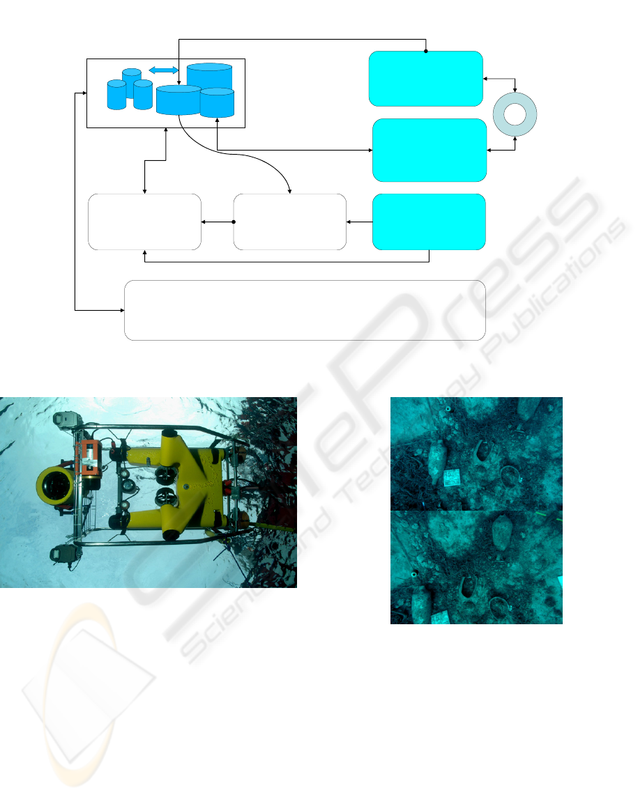
Archaeological
data
Photogrammetry
Photo
3D
database
Photogrammetric
survey
Orientation
with Photomodeler
Photogrammetric
survey
Amphorae measure
Virtual reality generated from Database
A tool for ‘reading’ the site in laboratory,
revision, update …
Database and
new plotting
inconsistensy check
Data fusion
Bathymetry,
multi beam.
DTM for seabed
representation
DGPS
USBL
Theoretical model
Figure 1: Synoptic schema of surveying process.
Figure 2: Tthe ROV in water with digital camera and
flashes in their housing.
The ROV has made a survey on the zone delimited
by the markers. The pilot use a video camera located
on the bow. He can see the markers and pilots in
order to make strips. (Conte et al., 2007). The pho-
tographs were taken in two modes:
- Manually, an operator, looking thought the lens
by a small video camera to shoot the image.
- With a fixed frequency, decided according to
the ROV speed and altitude.
Figure 3: Two photographs from a strip made by the
ROV.
3.2 Multimedia Calibration
The camera calibration in multimedia photogram-
metry is a problem already identified since almost
50 years.(Bass and Rosencrantz, 1973), (ASP,
1980). You can refer to Hans-Gerd Maas (Maas,
1995-a) to have an overview of the state of art of
this field. The problem is not obvious, the light
beam refraction through the different diopters (wa-
ter, glass, air) introduces a refraction error which is
impossible to express as a function of the image
plane coordinates alone. (Maas, 1995-b) Therefore
UNDERWATER PHOTOGRAMMETRY FOR ARCHAEOLOGY- The VENUS Project Framework
487
the deviation due to refraction is close to those pro-
duced by radial distortion even if radial distortion
and refraction are two physical phenomena of dif-
ferent nature.
For this reason we start to use standard photo-
grammetric calibration software and make a calibra-
tion of the set housing + digital camera. The distor-
tion corrects in a large part the refraction perturba-
tion. This was also shown by Kwon (Kwon, 1998)
(Kwon and Lindley, 2000).
But this approach is strongly dependent of the ul-
timate dioptr water/glass of the housing. To try to
minimize the refraction error we can found on the
market some housing with a hemispherical glass,
which is the case of Subal™ housing used with the
diver. For the other one, made by COMEX the glass
was plate and the refraction action is much more
important.
We have developed a method to compensate
separately refraction and distortion; this is published
as a deliverable of the VENUS project and is
downloadable from the VENUS web site.
3.3 The Reference System
The choice of a reference system to express the
measured data is very important. It’s depending of
the archaeological needs. Several cases can occur:
- We don’t have any way to get an absolute posi-
tion, or we don’t need it. In this case we have to
define the reference system on local, observable
geometry. For example something which defines
the axis of symmetry of the wreck (if there is
one); buoys to define the vertical axis; scale bar.
- We need an absolute orientation and we have
several ways to obtain it. For example a pipe line
as DGPS – USBL can give an approximation of
the ROV position, etc…
In Pianosa we will use an absolute reference
given in two modes: when it will be possible ISME
will associate for each photographs coming from the
ROV six parameters as: x, y, z, Omega, Phi, Kappa.
In the same time they will measure the absolute
coordinates of a set of markers seen on the photo-
graphs and used as control points.
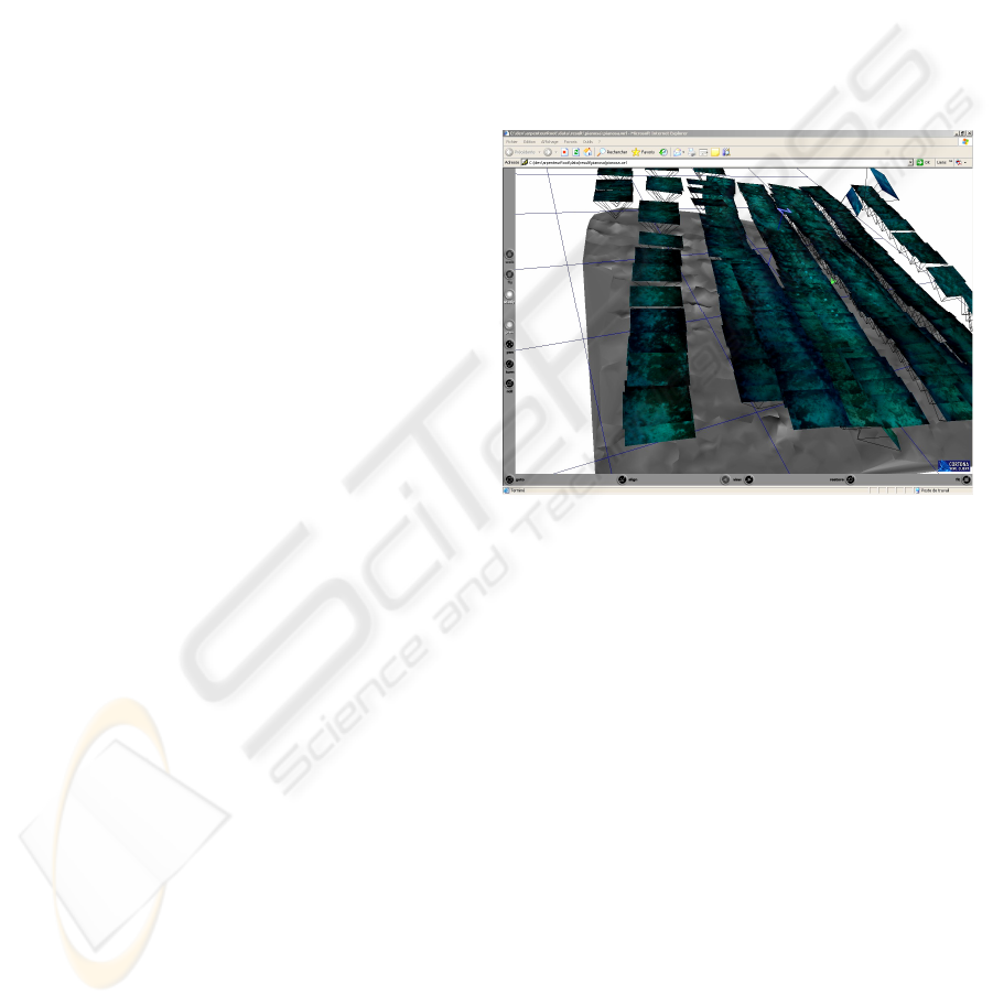
3.4 Orientation Phase
More than three hundred photographs have been
taken by the diver. They cover an area of 20 x 20
meters. The orientation was done manually using
Photomodeler™.
The photographs orientation was done using
points on the seabed, except on the amphorae in
order to be used to define a DTM on the seabed. The
oriented photographs and the diver’s trajectory are
visible in figure 5.
Five markers, visible in figure 4, were used as con-
trol points.
3.5 Amphorae Plotting
Using the oriented photography a plotting phase,
driven by archaeological knowledge is processed to
obtain both 3D model representing the amphorae
and a database managing all the data of the project.
Figure 4: Oriented photographs visualised in VRML with
the non textured seabed.
A Method for Measuring Amphorae. After the
orientation phase we shall, in the next months, start
the amphorae plotting phase. This second step will
use archaeological knowledge to obtain a complete
representation of the measured artefact; it will be
articulated in three steps:
1) Development of the theoretical model: for
each identified object, a geometrical description
offers a whole of geometrical primitives, which are
the only objects to be potentially measured, and a
theoretical representation of the object. In our case
archaeologists have identified six amphora typolo-
gies and we shall produce a theoretical model for
each of them. This theoretical model is formalized in
a hybrid way, taxonomy of archaeological artefacts
and an XML representation for the Amphorae ty-
pology.
2) As photogrammetric measurements are highly
incomplete (the object is seen only partially or may
be deteriorated), an Expert System will determine
the best strategy to inform provide all the geometri-
GRAPP 2008 - International Conference on Computer Graphics Theory and Applications
488
cal parameters of the studied object, starting from
the measurement process and handling the default
data as defined in the archaeological model and the
geometrical model. The expert System used is Jess.
(http://herzberg.ca.sandia.gov/jess/)
3) The resulting object is thus based on a theo-
retical model, dimensioned more or less partially by
a photogrammetric measurement. During the exploi-
tation of the photographs the operator can choose
the number of attributes of the object which are
relevant to measure. The choice of attributes will be
revisable in time, as for example during a second
serie of measurements. The system can be used to
position in space some objects from a catalogue
after a scaling process.
All these development are done in Java and con-
nected to the Arpenteur photogrammetric toolbox.
(Drap et al., 2003), (Drap and Long, 2005).
Measuring Paradigm Amphorae. In order to use
the method describe above, the archaeologists have
taken up six amphorae from the site. These ampho-
rae will be used as paradigm to define the theoretical
model needed. The first step is to measure the am-
phorae and to define a geometrical model. Some
amphorae have been designed in a traditional way at
scale 1:1, for some others as for example the type
gauloise 3 we used the typology presented by our
partner ADS Archaeological Data Service, Univer-
sity of York, UK.
(http://ads.ahds.ac.uk/catalogue/archive/amphora
_ahrb_2005/details.cfm?id=135)
The Plotting Interface. The diversity of the objects
handled by the archaeologists and the geometric
complexity of their surfaces led us to search for
stable morphological characteristics of the objects
where diagnostic measurements could be taken. A
series of simple geometric primitives are used to
approximate these morphological characteristics and
are used as an interface between the photogrammet-
ric measurement and the underlying model.
In the case of amphorae we define four measur-
able zones, rims, handle, belly, bottom, and we use a
set of geometrical primitives computed by least
square method onto the measured points. For exam-
ple a circle on the rim or belly points, a line on bot-
tom point and center of these two circles.
This interface allows the user (generally an ar-
chaeologist) to
- Recognize the amphora type on the photo-
graphs,
- Choose the amphora type in the interface
combo box (The site was already studied in
collaboration with archaeologists to define the
typology),
- Measure a set of points on the zone where
measure is allowed,
- Add archaeological comments and observa-
tions,
- Compute the object, using the measured points
to construct a new instance of amphorae,
- Insure consistency between observations and
theoretical model,
- Store this new instance in the remote database.
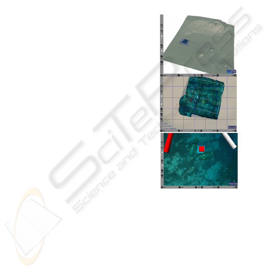
Figure 5: VRML representation of reconstructed ampho-
rae. Also visible the measured points on amphorae, a
marker and two scale bars. The seabed is textured using
the oriented photographs.
4 MERGING RESULTS
We have merged the data coming from the bathym-
etry mission, conducted by Geosystem Parma, Italy,
the photogrammetric campaign ie, a survey of the
seabed at large scale with a good quality texture and
a survey, driven by archaeological knowledge of all
the amphorae and fragments of the site with a direct
link from the Amphorae representation to the data-
base. (see fig 9 to 11).
UNDERWATER PHOTOGRAMMETRY FOR ARCHAEOLOGY- The VENUS Project Framework
489

All these data now are stored in a relational data-
base (MySql) and a set of java tools allows to wrap
objects from the database and to produce a VRML
representation.
The VRML file produced contains a link for
every amphora to the database via a PhP interface.
This interface allows the user to see, check and
modify the archaeological values regarding the am-
phorae. Of course the user has access to all the data,
i.e. measuring points, photos and photo orientation
used to measure the artefact, but these data are read
only through this interface.
4.1 Seabed Representation
The textured seabed is obtained by triangulation of
the points used to orient the photographs. We have
developed a tool to link each triangle to a set of
possible photographs for texturing with the current
used photograph mentioned. The result (3D points,
triangle, oriented photographs) are written in XML
with possible transformation to X3D and VRML.
This way is very convenient to change the photo-
graph used to texture a triangle or a zone.
4.2 Accuracy
The bundle adjustment precision for all the photo-
graphs is around 2 cm and the relative uncertainty of
measurement is less than 5mm when the signal is
good. The absolute accuracy is around 40cm (using
the control points given by the acoustic measure-
ment from the ROV).
5 CONCLUSIONS AND FUTURE
WORK
Archaeologists need to explore and make an inven-
tory of deep wreck sites unreachable by divers as
these sites may be jeopardized by deep trawling in
the very next few years. The digital preservation
aspect is one of the main goals of this project.
We have presented here the underwater survey
process from taking photographs to the site recon-
struction, merging acoustic and optical data, and a
theoretical model based on archaeological knowl-
edge for amphorae. In the framework of the VENUS
project a work is in progress to define ontologies for
underwater archaeology and more precisely for
amphorae present on the site. (Jeansoulin and Pap-
ini, 2007)
The measured object are stored in a database and
wrapped in Java Objects able to generate their mor-
phology in VRML.
In addition of the site survey presented here we
plan to immerse archaeologists inside a virtual uni-
verse depicting a reconstructed archaeological site,
for example a shipwreck, and allow them to work on
this site as naturally as possible. The digital model
generated by the survey will then be used, with the
help of virtual reality and mixed reality, for con-
structing immersive, virtual environments that en-
able archaeologists and general public to experience
an accurate and fully immersive visualization of the
site.(Chapman et al., 2006).
The next VENUS mission in open sea is sched-
uled in October 2007. It’s about a shipwreck, lo-
cated at Sesimbra, near Sado river mouth, south of
Lisbon, lying at a depth of 55m. It is yet possible to
dive and we will use both divers and ROV to fi-
nalyse our survey procedure. The ultimate mission
in France, scheduled in October 2008, will be done
completely diverless.
ACKNOWLEDGEMENTS
The Venus sea trial operations in Pianosa have been
made possible thanks to the voluntary support of a
number of different Institutions. In particular, the
Italian Ministery of Internal Affairs - Corpo Nazion-
ale dei Vigili del Fuoco - Direzione Regionale Vigili
del Fuoco della Toscana - Nuclei Sommozzatori
(Diving team of the Tuscany Fire Brigade) has made
available the ship and diving teams for assistance in
all the stages of the activities. The Italian Ministeries
of Justice (Casa di reclusione di Porto Azzurro,
Polizia Penitenziaria), of Transportation and Navi-
gation, of the Environment (Parco Nazionale Arci-
pelago Toscano) have given the necessary permits
and the required logistic assistance. The Cooperativa
Ormeggiatori Piombino, Studio Archeologico The-
tys and Geosystem Parma have contributed in the
data gathering process and with diving assistance.
VENUS is partially supported by the European
Community under project VENUS (Contract IST-
034924) of the "Information Society Technologies
(IST) programme of the 6th FP for RTD".
The authors are solely responsible for the content
of this paper. It does not represent the opinion of the
European Community, and the European Commu-
nity is not responsible for any use that might be
made of data appearing therein.
GRAPP 2008 - International Conference on Computer Graphics Theory and Applications
490

REFERENCES
Paul Chapman, et al. VENUS, Virtual ExploratioN of
Underwater Sites. in VAST/CIPA The 7th Interna-
tional Symposium on Virtual Reality, Archaeology and
Cultural Heritage. 2006. Nicosia, Cyprus: Archaeo-
lingua, Budapest, Hungary.
Pierre Drap, et al. Vual Reality in underwater archae-
ology: First results on the case study “L’Anse des
Catalans”, Marseille. in VSMM2005 Eleventh Inter-
national Conference on Virtual System and Multime-
dia. 2005. Ghent, Belgique.
Luc Long. L’archéologie sous-marine à grande
profondeur: fiction ou réalité. in Archeologia
Subacquea, Come opera l’archeologo sott’acqua,
Storie dalle acque, VIII ciclo di lezioni sulla ricerca
applicata in archeologia, Certosa di Pontignano, .
1996. Siena, Italia.
Giuseppe Conte, et al. Robotics tools for underwater
archaeology. in ECSAC07 VII International Confer-
ence on Science, Arts and Culture. Science for Cul-
tural Heritage. 2006. Veli Lošinj, Croatia.
Giuseppe Conte, et al. Data gathering in underwater
archaeology by means of a remotely operated vehicle.
in XXI CIPA international Symposium. 2007. Athens,
Gree: The CIPA / VAST, Nicosia, Cyprus.
Georges F. Bass and Donald Rosencrantz. L’utilisation
des submersibles pour les recherches et la cartogra-
phie photogrammétrique sous-marine. in
L’archéologie subaquatique, une discipline naissante.
1973. Paris.
ASP, Manual of photogrammetry, Fourth Edition. 1980:
American Society of Photogrammetry( Asprs Pubns).
Maas, H.-G. New developments in Multimedia Photo-
grammetry. in Optical 3-D Measurement Techniques
III. 1995: Wichmann Verlag, Karlsruhe.
Hans-Gerd Maas. New developments in Multimedia Pho-
togrammetry. in Institute of Geodesy and Photogram-
metry, Swiss Federal Institute of Technology. 1995.
Zurich.
Kwon, Y.-H. Refraction at the Water-Air Interface. 1998
(cited; Available from: http://kwon3d.com/theory/
dlt/refr.html).
Kwon, Y.-H. and S. Lindley, Applicability of 4 Localized-
calibration Methods in Underwater Motion Analysis.
XVIII International Symposium on Biomechanics in
Sports., 2000.
Pierre Drap, Julien Seinturier, and Luc Long. A photo-
grammetric process driven by an Expert System: A
new approach for underwater archaeological survey-
ing applied to the ‘Grand Ribaud F’ Etruscan wreck.
in Applications of Computer Vision in Archaeology
ACVA’03 2003. Monona Terrace Convention Center,
Madison, Wisconsin, USA.
Pierre Drap and Luc Long, Photogrammétrie et archéolo-
gie sous-marine profonde. Le cas de l’épave étrusque
Grand Ribaud F XYZ, 2005. N°103, partie 1 et N°
104, partie 2.
Robert Jeansoulin and Odile Papini.
Underwater archaeo-
logical knowledge analysis and representation in the
VENUS project: a preliminary draft. in XXI CIPA in-
ternational Symposium. 2007. Athens, Greece.
UNDERWATER PHOTOGRAMMETRY FOR ARCHAEOLOGY- The VENUS Project Framework
491
