
IT SERVICE MANAGEMENT OF USING HETEROGENEOUS,
DYNAMICALLY ALTERABLE CONFIGURATION ITEM
LIFECYCLES
David Loewenstern and Larisa Shwartz
IBM T. J. Watson Research Center, 19 Skyline Drive, Hawthorne, NY, U.S.A.
Keywords: IT service management, ITSM tools, heterogeneous dynamically alterable lifecycles, configuration
management, CMDB, ITSCM.
Abstract: IT service management requires the management of heterogeneous artifacts such as configuration items
with differing lifecycles and complex interrelationships. Lifecycle management in such environments is
critical in providing feedback and control between processes and sustaining communication and
synchronization between and within processes while maintaining the integrity of the configuration item
database (CMDB). We propose a method for managing lifecycles of multiple types, with automated
methods for inheritance of lifecycles, authorization of state changes, propagation of state changes through
relationships, and dynamic lifecycle updates.
1 INTRODUCTION
The provisioning of IT services has required
increasingly large, complex and distributed IT
environments, in which intended improvements can
easily have costly unforeseen consequences. The age
of monolithic tools for managing large-scale
information technology (IT) systems has gone. A
hope of containing the change within one IT service
tool that assembling procedures and services defined
has vanished. ITIL (OGS, 2007), the recognized
standard for IT service management, establishes as a
matter of fact that managing complex IT
environments requires coordination and careful
integration of existing services and processes. Each
business process could embody its own data and
own process management. Furthermore, a single
process, such as configuration management for
example, could manage various types of data in such
supporting variety of concepts and formalisms.
Therefore, one of the important tasks of ITSM is to
establish communication and synchronization
between and within processes so they behave in
consistent way and appear to providers and
consumers as a united business process support.
ITIL defines lifecycles as follows:
Lifecycle - the various stages in the life of an
IT Service, Configuration Item, Incident,
Problem, Change, etc. The Lifecycle defines the
Categories for Status and the Status transitions
that are permitted. For example:
■ The Lifecycle of an Application includes
Requirements, Design, Build, Deploy, Operate,
Optimize
■ The Expanded Incident Lifecycle includes
Detect, Respond, Diagnose, Repair, Recover,
Restore
■ The Lifecycle of a Server may include:
Ordered, Received, In Test, Live, Disposed, etc.
(OGS, 2007, page 302)
Lifecycles through specialization and coordination
can provide feedback and control between functions
and processes within and across various services of
IT service management.
ITIL recommends that configuration of the
environment be maintained in a carefully-controlled
configuration management database (CMDB). The
CMDB includes the authorized attributes of and
relationships between the configuration items (CIs)
in the IT environment needed to support impact
analysis of proposed changes to the environment.
It needs to be emphasized that the CIs form a
heterogeneous collection: CIs may represent
hardware, software, documentation or even non-IT
objects that impact the IT environment. Therefore
different CIs may have different collections of
attributes, different permitted relationships, and
particularly different lifecycles: collectively,
155
Loewenstern D. and Shwartz L. (2008).
IT SERVICE MANAGEMENT OF USING HETEROGENEOUS, DYNAMICALLY ALTERABLE CONFIGURATION ITEM LIFECYCLES.
In Proceedings of the Tenth International Conference on Enterprise Information Systems - ISAS, pages 155-160
DOI: 10.5220/0001718401550160
Copyright
c
SciTePress

different types of CIs. Different lifecycles may have
little in common: hardware assets may be specified,
purchased, configured, deployed and
decommissioned; software may be designed,
developed, tested and installed; contracts may be
negotiated, approved and fulfilled. Certain
transitions from state to state within a particular
lifecycle may require supporting approvals, but an
otherwise identical transition in an otherwise
identical lifecycle in a CI with a similar type may
require different handling.
Transitioning a CI from one lifecycle state to
another is itself a type of change that can impact the
IT environment. At minimum, state changes in one
CI often require changes in the containment
hierarchy rooted at that CI: e.g., decommissioning a
hardware asset normally makes software installed on
that asset unusable. A challenge, then, is to provide a
systematic way to propagate CI lifecycle state
changes across CMDB relationships given
heterogeneous CI lifecycles.
Although successful implementation of a CMDB
requires management of CI lifecycles, the same sort
of lifecycle management can be applied to objects
that are not typically thought of as configuration
items. For example, service processes themselves
have lifecycles but are too ephemeral for a CMDB,
and documents created on-line have lifecycles but do
not represent anything in the IT environment.
While a substantial amount of work has been
done in such areas as product lifecycle management
(see for example Stark, 2005), telecommunications
networks, and knowledge management (see for
example Siemeniuch, 1999); it hasn’t been
addressed considerably within IT service process
management. This paper describes a method for
managing CI lifecycles satisfying the following
requirements:
• CI types form one or more hierarchies (with the
degenerate case that the CI types form no
structure at all). CI lifecycles are associated
with CI types. CI types inherit the lifecycle of
their parent in the hierarchy by default.
• Lifecycles for different CI types may differ in
all qualities.
• Lifecycles may be altered dynamically (i.e.,
without removing the CMDB from service).
• Rules for propagating lifecycle changes across
relationships between CIs may be created
dynamically.
• Rules for requiring supporting approvals for
CIs entering or leaving certain states may be
created dynamically.
• Rules for requiring supporting approvals for
changes to any CI attribute when the CI is in a
particular state, may be created dynamically.
Figure 1: An example lifecycle with states of Not Ready,
Decommission, Production, Under IM, On Hold. The
Production state is protected.
This paper will then go on to describe one of
possible implementations of CI lifecycle
management and implementation involving both CI
lifecycles and lifecycles of non-CI objects such as
recovery plans.
2 METHOD
2.1 Lifecycle Representation
A lifecycle, as shown in figure 1, may be understood
as a directed graph comprised of labelled states,
together with the transitions between the states. The
states represent the legal states for a particular
category of item; the transitions represent operations
on the items (e.g., approval, placed into service, etc.)
that change the state of an item. States in a lifecycle
may be flagged to associate the states with particular
policies that restrict requirements that must be
satisfied to enter or leave the state.
In figure 1, the Not Ready state is flagged as the
initial state for the lifecycle and the Production state
is flagged as a “protected” state requiring an
approved request for change to enter or leave.
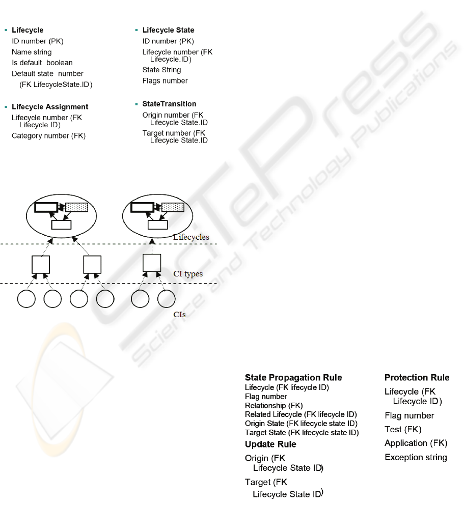
More completely, a lifecycle is comprised of a
lifecycle description, lifecycle states, state
transitions, and assignments as detailed in figure 2.
The lifecycle description contains a label for the
lifecycle; a flag marking whether the lifecycle is the
“default” lifecycle, to be used in the absence of
assignments and which lifecycle state is the default
state of the lifecycle; and a marker indicating which
ICEIS 2008 - International Conference on Enterprise Information Systems
156
lifecycle state is to be considered the default state of
the lifecycle, to which newly created objects
associated with the lifecycle are to be assigned. A
lifecycle state is a named entity associated with a
single lifecycle; it is associated with zero or more
flags (represented as a binary number) which
identify policies associated with the state. A state
transition is an unnamed entity that maps origin
states to target states in the same lifecycle. Lifecycle
assignments map lifecycles onto other database
objects such as configuration items (CIs).
Figure 2: Database tables for lifecycles and their
components and assignments.
Figure 3: Lifecycle assignment structure for Configuration
Items.
2.2 Lifecycle Assignment
Lifecycles may be associated with item categories
through the Lifecycle Assignment table (figure 2). In
the case of configuration items (CIs), these
categories are CI types, such as servers or
workstations. There could be as many as one
lifecycle designated for each category, but in most
cases this is unnecessary: multiple categories may
share a lifecycle via entries in the Lifecycle
Assignment table (figure 3). Where categories are
arranged in a tree-structured hierarchy (with
categories lower in the hierarchy considered to be
subcategories of those above them), categories
without entries in the Lifecycle Assignment table are
assumed to inherit the assignment of the closest
ancestor with an entry in that table. If it is possible
for there to be categories that neither are assigned a
lifecycle explicitly nor inherit one implicitly, one
lifecycle should be designated the default lifecycle
to be used for such cases.
2.3 State Management
When a state change is requested for an item by a
user, the first step is to locate the lifecycle associated
with the item. As discussed in the previous section,
if a lifecycle is directly associated with the specific
subcategory of the item via the Lifecycle
Assignment table, then that lifecycle is used.
Otherwise, the lifecycle is inherited or the default
lifecycle is used.
The next step is to determine whether the item’s
current state exists in the lifecycle. It is possible that
it may not due to changes in either the lifecycle or
the item: lifecycles may be created, edited, deleted,
or reassigned, or items may be moved to new
categories. If not, then the state is updated according
to the update rules described later.
Next, the current state, called the origin state, is
checked against its lifecycle to see if there are any
associated flags according to the Lifecycle State
table. If there are, then any protection rules
associated with those flags are checked as described
later. If all protection rules are satisfied, or if none
exists, then a list of possible target states as
determined by the State Transition table is generated
and the user is prompted to choose one. This
selected target state is then also checked for its
protection rules using the same mechanism used for
the origin state. If all protection rules are satisfied or
none exists, then the state change is recorded. A
detailed description of how protection rules are
satisfied is presented in the next subsection.
Figure 4: Database tables for propagation rules.
IT SERVICE MANAGEMENT OF USING H HETEROGENEOUS, DYNAMICALLY ALTERABLE
CONFIGURATION ITEM LIFECYCLES
157
2.4 State Propagation
After recording the state change, possible state
propagation across relationships may take place. An
item may be associated with zero or more
relationships to other items: these are stored in
separate tables unrelated to the lifecycle system,
such as in a CMDB. Relationships describe a
connection between two items as well as a
relationship type: multiple relationships may share a
type (figure 5). Examples of relationship types
include “contains”, “requires”, “creates”, and there
may be many others: one of the primary purposes of
a configuration management database is to maintain
these relationships.
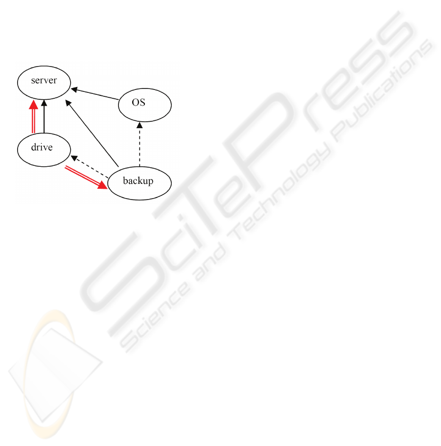
Figure 5: Relationships among Configuration Items. The
solid arrows are “mounted on” relationships and the
dashed arrows are “requires” relationships. The red double
is state propagation (see text).
The State Propagation table (figure 4) allows
state changes to be propagated through such
relationships so that, for example, taking a piece of
hardware offline can also mark all of its software as
unavailable. A row of the State Propagation table is
interpreted as: if the item is associated with the
Lifecycle specified in the row, and the target state to
which the item has transitioned is flagged with the
Flag listed in the row, then any relationships of the
type Relationship listed in the row from the item to
an item associated with the Related Lifecycle that
are in the Origin State are transitioned to the Target
State. All propagations are considered to be
performed simultaneously, and the process is
checked to prevent cycles. In the example in figure
5, the tape drive’s state is moved to “offline” in
response to a repair request. A propagation rule
changes the state of the server to “not ready”
because the server is only partially operational, and
another rule changes the state of the backup software
to “offline” because it depends on the tape drive.
2.5 Dynamic Lifecycle Alteration
Dynamic lifecycle management presents an
interesting challenge. Many sources only consider
cases in which lifecycles cannot be altered after they
are in production. The requirements of data integrity
support this train of thought. However, in constantly
changing business environments and fast
progressing technology that supports them, the
restriction of preserving lifecycle states for the life
of the process or even of the implementation could
significantly and unreasonably limit the flexibility of
business adaptation. Our implementation of a
lifecycle allows a full dynamicity. It raises a number
of interesting questions presented below.
If an item is discovered to be in a current state
that does not exist in its associated lifecycle, for
example if the lifecycle is edited, then one or more
update rules are applied to correct the state. An
item’s current state may not be in its associated
lifecycle because the item’s category has changed,
because its original lifecycle has been edited or
deleted, or even because a category containing the
subcategory of the item has been assigned to a
different lifecycle. The process for updating the
lifecycle is a breadth-first search through the Update
Rule table (figure 4):
• All rows of Update Rule for which the Origin
matches the item’s current state are selected.
• From this selection, all rows for which the
Target state is associated (via the Lifecycle
State table) with the item’s current lifecycle are
selected. If this new selection is not empty, it
replaces any previous selection.
• The Target states from the selection, if any, are
added to a list of states, which is initially empty.
Duplicates are removed.
• If the list of states is now empty, stop and report
an error.
• The next element of the list of states replaces
the item’s current state.
• If the item’s current state is now in the item’s
associated lifecycle, stop and record the state
change. Otherwise, repeat this list.
2.6 Protection Rules
Lifecycle states may be associated with protection
rules; such states are called protected states. A state
is protected if its flags contain (bitwise AND) the
flag of any row of Protection Rule and their
Lifecycle fields match. Each row of Protection Rule
is a protection rule. Each protection rule includes a
test ID and an exception, and optionally the ID of an
application. The tests corresponding to the test IDs
ICEIS 2008 - International Conference on Enterprise Information Systems
158

are currently implemented as stored SQL queries
that can examine the contents of the fields of the
item whose state triggered the protection rule. The
tests can also examine the item’s relationships and
the fields associated with items to which it has a
relationship. The lifecycle state passes the test if
there is some entry in the database that matches the
SQL query. If a lifecycle state does not pass the test,
then the given exception is signalled to the user. If
the protection rule contains a pointer to an
application, that application is run, permitting the
user to create or modify fields and relationships for
the item, and then the test is run again. This process
enables the lifecycle designer to force a user to
supply missing information for an item or related
items.
3 ITSCM AND CHANGE
MANAGEMENT
One of the IT Service Management processes
defined in ITIL, IT Service Continuity Management
(ITSCM), has the purpose of ensuring service
continuity in the event of a major outage. It stands
out among other ITIL processes particularly in that
while other processes in ITIL v.3 have a limited set
of defined activities, ITSCM also defines stages for
specific activities. ITSCM has primary interfaces to
all major processes of IT Service Management
(figure 6):
• Change Management,
• Incident Management,
• Problem Management,
• Availability Management,
• Service Level Management,
• Capacity Management,
• Configuration Management and
• Information Security Management.
The ability to keep all interfaces synchronized is
critical for ITSCM (see e.g., Toigo, 2003). The
design and implementation of this complex task is
not addressed in ITIL. Consider that changes to the
service infrastructure must be reflected in changes to
the recovery plan, and so ITSCM artifacts must be
managed under change control. Changes to
configuration items, both authorized and
unauthorized, could result in devaluation of the
recovery plans.
To automate detection of plan devaluation, the
recovery plan can be placed into the CMDB with
depends-on relationships to its CIs (figure 8). Better,
the recovery plan can be represented as a composite
containing plan sections, each represented in the
CMDB, with containment relationships linking the
plan with its sections. This fine-grained
representation of the recovery plan permits the
Figure 6: ITSCM and its interfaces.
IT SERVICE MANAGEMENT OF USING H HETEROGENEOUS, DYNAMICALLY ALTERABLE
CONFIGURATION ITEM LIFECYCLES
159
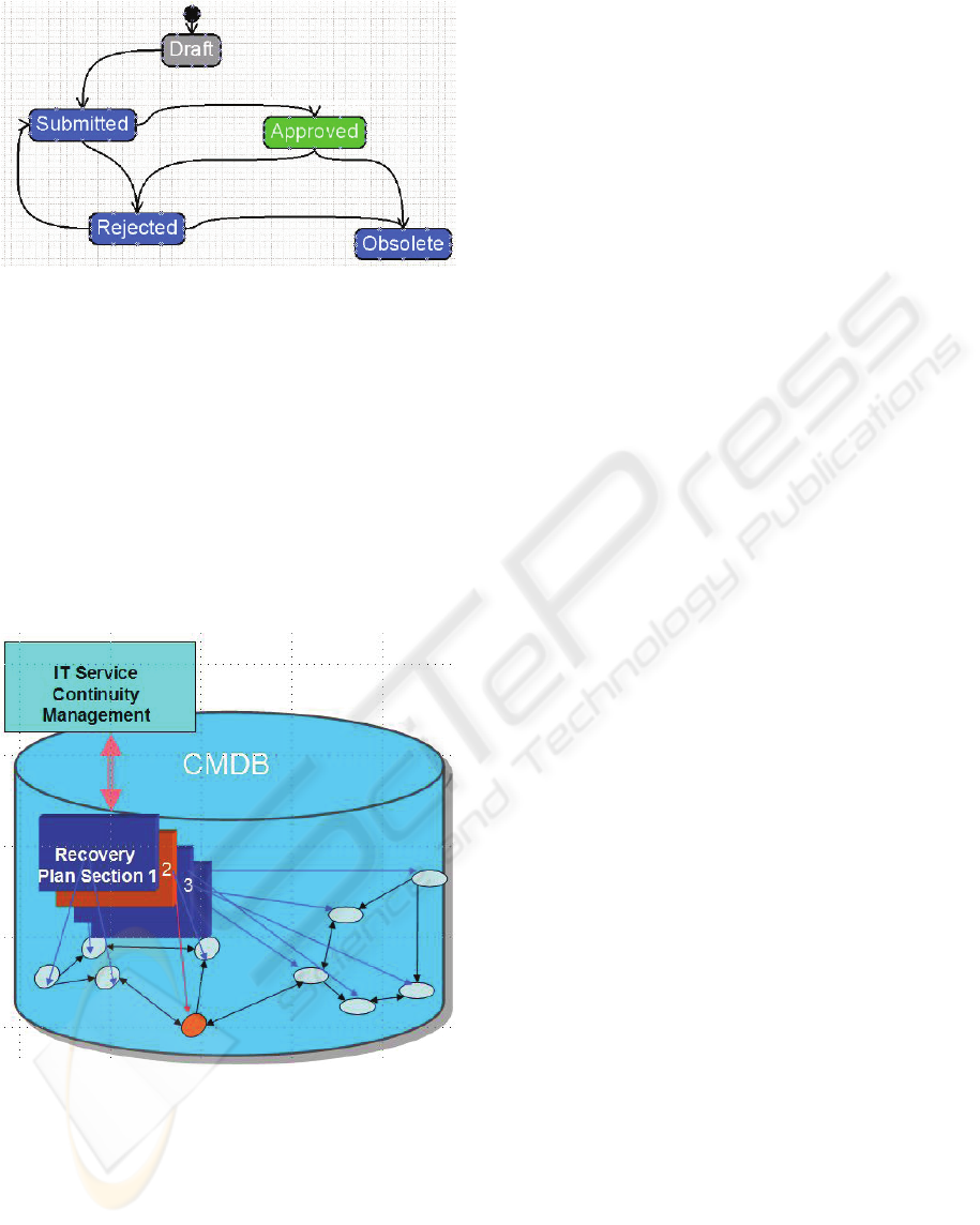
Figure 7: An example of a lifecycle for a recovery plan.
The Approved state is protected.
creation of rules relating changes to states of specific
configuration items to sections of the recovery plan
to which they have a relationship, therefore making
it possible to make a focused impact analysis
highlighting exactly which part of a recovery plan
must be revised. The recovery plan itself as well as
each of its components would have their own
lifecycles, with propagation and protection rules to
determine the relationship between the state of the
individual sections and the state of the recovery plan
as a whole.
Figure 8: Relationships among CIs and recovery plan
sections.
Sample rules for a state transition can be defined
for illustration purposes. In figure 8, a recovery plan
section can enter the protected Approved state only
if at least one configuration item is identified in
recovery plan as a system dependency (i.e., the plan
section has a depends-on relationship to the CI) and
all such CIs are in the production state. The recovery
plan as a whole can enter the Approved state only if
all of its sections are in the Approved state and in
addition there is a valid system-user assigned as the
primary contact. A corresponding propagation rule
moves the appropriate recovery plan section to the
rejected state when a CI to which it has a
dependency leaves the production state, and another
moves the recovery plan to the rejected state when
any of its sections enter the rejected state. Still
another rule can be triggered by the recovery plan’s
state change to initiate a change management
process for the recovery plan.
In this example different lifecycles are
associated with related artifacts, but common
approach and propagation rules allow the feedback
and smooth transition between processes in order to
facilitate integrated approach to managing IT
Services which support business lifecycle.
4 CONCLUSIONS
Providing a common approach to lifecycle
management helps to facilitate an integrated
approach to IT Process Management and so to avoid
duplication of costs, both in labor and infrastructure.
This approach is possible using dynamically
alterable lifecycles. Furthermore it could be used to
manage lifecycle state hierarchy and identify and
resolve conflicts, in such helping to enhance
reliability in overall IT Service management by
providing some capabilities for self-managing
services.
REFERENCES
Kern A., Kuhlmann M., Schaad A., and Moffatt J., 2002.
Observations on the role life-cycle in the context of
enterprise security management, in Proceedings of the
seventh ACM symposium on Access control models
and technologies, ACM, pp. 43-51.
OGS, 2007. ITIL: Service Design, TSO, Norwich.
Stark, J., 2005). Product Lifecycle Management, Springer,
London, 1
st
edition.
Siemieniuch C.E., Sinclair M.A, 1999. Organizational
aspects of knowledge lifecycle management in
manufacturing. In International Journal of Human-
Computer Studies, Volume 51, Number 3, pp. 517-
547(31), Academic Press.
Toigo, J.W., 2003. Disaster Recovery Planning:
preparing for the unthinkable, Prentice Hall PTR, 3rd
edition, pp. 424-238.
ICEIS 2008 - International Conference on Enterprise Information Systems
160
