
LOW-VOLTAGE SCRATCH-DRIVE MICRO-SCALPELS
CONTROLLED BY A BINARY-ENCODED SIGNAL
Jung H. Cho and Mark G. Arnold
Lehigh University, Bethlehem, Pennsylvania, U.S.A.
Keywords: MEMS, SDA, Micro-robot, Micro-scalpel.
Abstract: A novel approach to applying multi-stylus MEMS SDA Scratch-Drive-Actuator (SDA) micro-robots to aid
in the diagnosis and treatment of dermatological conditions is presented. The operation of MEMS SDA has
been well demonstrated by the research of (Donald et al., 2008) (Donald et al., 2006)(Donald et al., 2003).
We assume that such SDAs may be applied to the skin and powered by a bandage-like substrate. A method
of controlling the turning operation of MEMS SDA Scratch-Drive-Actuator (SDA) micro-robots has been
developed previously by our research: adding an additional stylus arm to control left and right rotation as
well as using both arms to halt. In order to control multiple micro-robots without the complication of
different stress curling that requires high voltages incompatible with dermatological applications, an
alternative solution of controlling electrical connection between the parallel-plate body and the stylus arms
is presented that uses a binary-encoded signal. Also an additional beam added to the body of SDA to be
used as micro-scalpel can be controlled by this same signal
1 INTRODUCTION
Micro-Electro-Mechanical Systems (MEMS) are
now commonly used in mirrors, optical gratings,
variable capacitors, and accelerometers. Micro-
robots fabricated from MEMS need four basic
components: power supply, sensors, control and
motion transducers. One of the most widely
researched MEMS transducer is the Scratch Drive
Actuator (SDA), which is an L-shaped beam of
poly-silicon that moves across a powered substrate
as a voltage is applied and released. The electrostatic
attraction between the substrate and the poly-silicon
deforms the “L” shape, making the SDA act like a
spring, which is released when the external voltage
is removed. An un-tethered micro-robot has been
developed (Donald et al., 2003) utilizing such
electrostatic actuation. Although this design has only
been demonstrated in isolation from any biological
material on top of the artificial environment of a
powered substrate, this position paper argues that for
some dermatological procedures, SDA-based micro-
robots, which are placed between a flexible
(bandage-like) powered substrate and the skin, may
be a useful diagnostic aid and may also enhance
surgical precision.
The MEMS micro-robot built by (Donald et al.,
2006) has a dimension of 60μm by 250μm by 10μm.
Figure 1 shows the structure of this device proposed
in (Donald et al., 2006), which propels itself forward
(moving the brushing towards the viewer in Figure
1) along the powered surface by bending and
releasing its large rectangular scratch-drive plate
(Donald et al., 2006). A stylus steering arm provides
single-direction turning capability (counterclockwise
as shown in Figure 1) by holding the robot stationary
at the dimple while the release of the main plate
provides torque. The approach taken by (Donald et
al., 2008) encodes the four micro-robot states (stylus
up plate up, stylus up plate down, stylus down plate
up, stylus down plate down) with four different
voltage levels. Donald et al. have generalized the
multi-voltage-level encoding (Donald et al.,
2008)(Donald et al., 2006) to control multiple robots
from a single external signal by using hysteresis
built into the design of each SDA (different chip
dimensions corresponding to different activation
voltages). Having multiple robots operating
simultaneously would give more information and
greater control to the surgeon, but with the (Donald
et al., 2008) multi-voltage encoding, the full voltage
swing may be hundreds of volts, a level which may
not be safe or comfortable for the patient.
219
Cho J. and Arnold M. (2010).
LOW-VOLTAGE SCRATCH-DRIVE MICRO-SCALPELS CONTROLLED BY A BINARY-ENCODED SIGNAL.
In Proceedings of the Third International Conference on Biomedical Electronics and Devices, pages 219-223
DOI: 10.5220/0002760202190223
Copyright
c
SciTePress
The approach we propose is different. Unlike
the multiple-robot system of (Donald et al., 2008) in
which each robot obtains its motion command via a
unique external voltage, we assume that the robots
have on-board digital logic capable of receiving a
binary-encoded command over a series of clock
cycles, and that each possible motion for each robot
has a unique binary code. In our proposal, each robot
will have identical SDA dimensions, and use digital
logic to make the behavior of each robot unique.
With the proper choice of geometry, scratch-drive
activation can happen around ten volts. The
additional voltage swing needed to transmit our
binary code is on the order of a volt, so that the total
voltage of the signal applied to the patient skin will
be imperceptible. Since there can be a measurable
difference in conductance between normal and
tumorous tissue (Smith et al., 1986), having a large
swarm of robots performing such measurements in
real time will help the surgeon minimize the amount
of tissue removed.
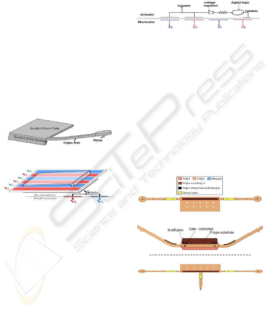
Figure 1: Illustration of MEMS Micro-robot (Donald et al.
2006).
Figure 2: Illustration of SDA on power grid (Donald et
al., 2006).
2 DUAL-STYLUS SDA WITH
MICRO-SCALPEL
Figure 2 shows the schematic of the capacitively-
coupled power grid used by (Donald et al., 2006).
By using these electrodes, the SDA operates by
attracting its body to the electrodes when external
high voltage is applied, and jumping like a spring
when the voltage is removed. Therefore, in order to
be propelled, a clock-like voltage waveform has to
be applied (Donald et al., 2006). In our novel
approach, the voltage on the scratch-drive plate can
also be used to supply power to on-board digital
logic as shown in Figure 3. We have demonstrated
this in our previous research by developing a
Verilog-A model of the SDA and applying voltage
regulation to provide adequate voltage swing for 1V
40nm CMOS standard-cells from the plate voltage
as a power (Cho and Arnold, 2009).
Figure 3: Equivalent circuit showing V
platehi
and V
platelo
.
In order to change direction, Donald’s SDA (Donald
et al., 2006) uses a stylus steering arm and requires
higher voltage to achieve pull-in or snap-down
voltage (Donald et al., 2006) necessary to make
contact with the substrate. This requirement
introduces multi-voltage level encoded power
waveform, which is used by Donald’s SDA. In
order for many SDAs to interact as shown in
Donald’s (Donald et al., 2008), all of them need to
have different stresses applied during fabrication so
that the stylus arms can curl differently in order to
vary the pull-in voltage (Saha et al., 2006). Our
novel approach is to apply a switch or a large
transistor to control the conductivity between the
stylus arm and the parallel-plate body. This
eliminates the step needed for different stress
curling, and one voltage waveform can be used to
supply power to different SDA micro-robots. We
(a)
(b)
(c)
Figure 4: (a) Top view of proposed SDA modification
from (Donald et al., 2006) in order to perform both left
and right turn. (b) Frontal view of proposed SDA
modification from (Donald et al., 2006) in order to control
pull-in/snap-down voltage of the stylus steering arms. (c)
Top view of proposed SDA modification from (Donald et
al., 2006) in order to include micro-scalpel.
BIODEVICES 2010 - International Conference on Biomedical Electronics and Devices
220
also added a second arm, as seen in Figure 4a and
4b, to be able to turn left and right, and use both
arms to enforce a stationary position. Figure 4c
illustrates the addition of a micro-scalpel beam
which can be used to probe or cut samples as
necessary.
The modified SDA consists of 3 components
which are left and right stylus beams and parallel-
plate capacitor body. Figure 5 shows the high-level
illustration of this structure. The capacitance across
the parallel-plate is the most dominant energy
storage part of this circuit. Since the V1 and V2
electrodes are uniformly covering the whole area of
the parallel-plate, the voltage across the plate can be
summarized as (Donald et al., 2003),
21
2211
CC
CVCV
V
plate
+
+
= (1)
When both arms are connected to the parallel plate
body, the voltage across the beams (V
left-arm
and
V
right-arm
in Figure 6), would be the same compared
to V
plate
.
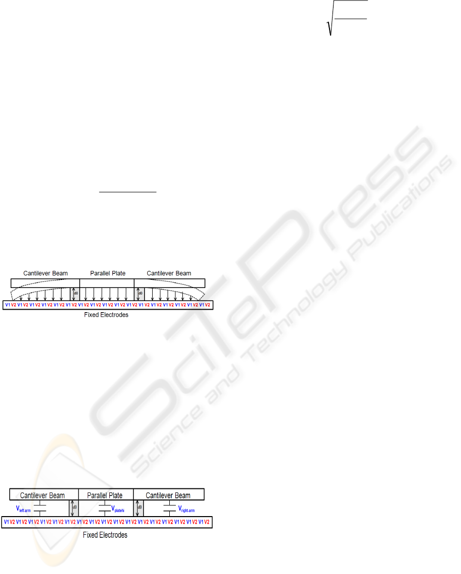
Figure 5: Deformation in cantilever and parallel plate due
to applied voltage.
When the beams are electrically disconnected, then
each stylus beam becomes a well-known MEMS
cantilever beam (Saha et al., 2006)(Wei et al., 2002).
We applied the modeling technique and equations
from Wei’s research (Wei et al., 2002) to build a
Verilog-A model to work with our previously
developed model of SDA. Figure 6 shows a different
voltage across the beams and the plate when arms
are disconnected. Under ideal fabrication process,
V
left-arm
and V
right-arm
would be identical.
Figure 6: Illustration of different voltage across the beams
and the plate capacitor due to disconnection from the
parallel plate body.
V
left-arm
, V
right-arm
and V
plate
represent the pull-in
voltage needed to cause attraction. This equation is
defined as (Saha et al., 2006),
A
kd
V
PI
0
3
0
27
8
ε
= (2)
Here ‘k’ is the spring constant, ‘d
0
’ is the initial gap
height and ‘A’ is the area coverage of the cantilever.
Previous research (Donald et al., 2008) influenced
V
PI
based on careful selection of these parameters,
‘k’ and ‘d
0
’. We will show that these parameters can
remain constant, and by simply connecting and
disconnecting the cantilever arms from the parallel
plate body electrically we can control the V
PI
. And
we will use this control in section V to present a
parallax algorithm which can be used to guide the
micro-robots with an on-board algorithm that does
not need external control.
3 INTERMITTENT POWER
AND MAGNETIC TUNNEL
JUNCTION NON-VOLATILE
FLIP-FLOP
As described in the previous section, a MEMS SDA
micro-robot is driven by external voltage using the
electrodes underneath to create an electrostatic field
and to cause actuation which is transferred into
forward or turning motions. This external voltage is
applied in clocked fashion around 1 KHz, which we
will refer to as a major cycle. Since the voltage is
applied intermittently, there needs to be a solution to
hold important states needed for continuous
operation of the on-board logic. This leads to
applying non-volatile flip-flops developed using
Magnetic- Tunnel-Junction (MTJ) technology (Zhao
and Belhaire, 2007). This flip-flop works like a
standard flip-flop but information is stored in MTJs;
therefore, when the SDA's major power cycle
occurs, the MTJ flip-flop restores to its previously
saved state. In order to demonstrate this we
simulated the MTJ flip-flop (Zhao and Belhaire,
2007) and developed Verilog-A model of a dynamic
storage behavior of MTJ. We then simulate this MTJ
flip-flop in Cadence AMS environment to co-
simulate both transistors and Verilog-A/Verilog-
AMS models.
4 DUAL-STYLUS SDA
SIMULATION
In order to demonstrate the operation of the dual-
LOW-VOLTAGE SCRATCH-DRIVE MICRO-SCALPELS CONTROLLED BY A BINARY-ENCODED SIGNAL
221
stylus SDA, we have developed a Verilog-A model
to capture the voltage across the beams and the
parallel plate. First, we verified that V
plate
can still be
used to supply power to the on-board CMOS digital
logic when two arms are connected and
disconnected. We have chosen 4 bit counter to
demonstrate the operation along with storage
behavior of the MTJ flip-flop from section III. A 4-
bit counter was synthesized from Verilog RTL into
40nm standard cells using positive edge flip-flops
and they were replaced with a MTJ non-volatile flip-
flop Verilog-A/AMS model. We then integrated all
the models to simulate in the Cadence AMS
environment. The setup is shown in Figure 7. This
type of system-level simulation utilizing Verilog-
A/Verilog-AMS models has been accepted in
research (Mateu and Moll, 2007).
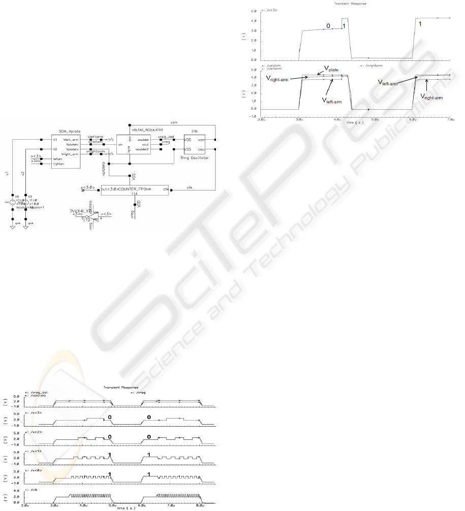
Figure 7: Top level simulation setup.
Figure 8 shows the simulation result of the counter.
The first waveform shows the intermittently-applied
and voltage-regulated output to drive the ring
oscillator and the counter. The next 4 waveforms are
output of the counter x[3:0]. As the power was
removed, the counter state was saved in the MTJ
flip-flop as 0011. When the power returned, it
restored the state 0011 and continued counting. This
result provided assurance that more elaborate state
machines can be pursued with this architecture.
Figure 8: Simulation result of 4-bit counter.
Then, we used the counter output bit x[3] to control
the left stylus and inversion of x[3] to control the
right stylus. Figure 9 shows the voltage across V
left-
arm
and V
right-arm
changing as x[3] toggles. As
expected, V
plate
remained constant during x[3]
change since it has the most capacitance to hold the
charge.
Figure 9: V
left-arm
, V
right-arm
and V
plate
result.
5 BINARY-ENCODED CONTROL
Section II through IV described support circuits
developed in order to control one dual-stylus micro-
robot. However, in order to control multiple micro-
robots there needs to be a global communication
channel necessary to operate them. We propose that
using the V1/V2 power grid described in section II
as a communication channel would be a solution to
this problem. The original V1 or V2 functional goal
has not changed and will continuously provide
propulsion and supply power to CMOS digital logic
on board the micro-robot. The architecture we
propose is while V1 or V2 is in a high state and
supplying power to on-board logic we can apply
higher frequency serial data onto V1 or V2 to
convey control information to each of the micro-
robots on the power grid. This idea is in line with
technology used to transfer data through power-lines
using frequency division multiplexing (Hensen,
1998). Figure 10 illustrates an example of using an
eight-bit binary signal to control the motion of four
robots (from a swarm that could contain up to thirty-
two robots). In this example, none of the micro-
scalpels are engaged (indicated by the most
significant bit of the 8-bit code); each robot number
(indicated by the middle 5-bit value) performs a
different move (indicated by the least two significant
bits).
BIODEVICES 2010 - International Conference on Biomedical Electronics and Devices
222

Figure 10: V1 / V2 are used as channels to apply binary
encoded controls to each micro-robot.
Each micro-robot is assigned a unique 5-bit number
and as part of the on-board logic there is an 8-bit
UART which recovers the serial communication and
programs each micro-robot for the operation it needs
to perform. When a particular micro-robot receives a
5-bit number that does not match its assigned robot
number, the robot in question ignores the three
command bits. If, on the other hand, the 5-bit
numbers match, the robot in question will latch the
three command bits into MTJ flip-flops so that at the
next major cycle the robot in question will perform
the command specified. The UART is clocked every
minor cycle, which operates at a much higher
frequency than the major cycle. Since transmitting
each 8-bit code requires a start and stop bit, the
bandwidth required on the global communications
channel for a swarm of 32 robots is at least
10*32=320 times the major cycle, and the UART
operates at some multiple of this. For example, if the
major cycle is 1 KHz and the UART requires 8
minor cycles per bit received, the minor cycle needs
to be about 2.5 MHz because the channel needs to
transmit at least 320,000 bits/second.
6 CONCLUSIONS
We have proposed a novel approach of applying
MEMS SDA micro-robots to assist in
dermatological procedures on the assumption power
may be applied via a bandage-like substrate. We
discussed features needed on a MEMS micro-robot
to achieve this. It needs improvement from Donald
et al. (Donald et al., 2006) to provide uniform
control for turning MEMS SDAs using a much
lower voltage signal that used by Donald et al. By
adding an additional stylus arm the robot can now
turn both left and right as well as use both arms to
stop. A third stylus arm provides a micro-scalpel.
Fabricating a transistor connection between each
stylus and the parallel-plate body allows the micro-
robot to control the pull-in voltage. Using this
control capability, we also presented a new approach
to using the power grid to communicate to each
micro-robot using a binary-encoded signal which
operates at much lower voltages than previous multi-
robot SDA systems.
REFERENCES
Bruce R. Donald, Christopher G. Levey, and Igor
Paprotny, 2008.
Planar Microassembly by Parallel Actuation of MEMS
Microrobots. In IEEE – Journal of Microelectro-
mechanical Systems, vol. 17, no. 4.
Bruce R. Donald, Christopher G. Levey, Craig D.
McGray, Igor
Paprotny, and Daniela Rus, 2006. An Untethered,
Electrostatic, Globally Controllable MEMS Micro-
Robot. In IEEE – Journal of Microelectro-mechanical
Systems, vol. 15, no. 1.
Bruce R. Donald, Christopher G. Levey, Craig D.
McGray, and
Daniela Rus, 2003. Power Delivery and Locomotion of
Untethered Micro-actuators. In IEEE – Journal of
Microelectromechanical Systems, vol. 12, no. 6.
W. Zhao, E. Belhaire, C. Chappert, 2007. Spin-MTJ based
Non-Volatile Flip-Flop. In International Conference on
Nanotechnology.
Loreto Mateu and Francesc Moll, 2007. System-level
Simulation
of a Self-powered Sensor with Piezoelectric Energy
Harvesting. In International Conference on Sensor
Technologies and Applications.
Shimul Chandra Saha, Ulrik Hanke, Geir Uri Jensen, and
Trond Saether, 2006. Modeling of Spring Constant and
Pull-down Voltage of Non uniform RF MEMS
Cantilever. In Behavioral Modeling and Simulation
Workshop, Proceedings of the 2006 IEEE
International, pp. 56-60.
Leow Cheah Wei, Abu Baker Mohammad and
Norazan Mohd. Kassim, 2002. Analytical Modeling For
Determination Of Pull-In Voltage For An Electrostatic
Actuated MEMS Cantilever Beam. In Proceedings of
ICSE2002.
Smith, Susan Rae, Foster, Kenneth R., Wolf, Gerald L.,
1986.
Dielectric Properties of VX-2 Carcinoma Versus Normal
Liver Tissue. In IEEE Transactions on Biomedical
Engineering, BME-33, 5, 522-524.
C. Hensen, 1998. Data transmission applications via low
voltage
power lines using OFDM technique. In 1998 IEEE 5th
International Symposium on Spread Spectrum
Techniques and Applications, 1, 210 – 214.
Jung H. Cho and Mark G. Arnold, 2009. Powering
Embedded
CMOS Logic on MEMS-based Micro-Robots. In IEEE
International Behavioral Modeling and Simulation
Conference, 73-77.
LOW-VOLTAGE SCRATCH-DRIVE MICRO-SCALPELS CONTROLLED BY A BINARY-ENCODED SIGNAL
223
