
A METHOD AND A TOOL BASED ON A CONCEPTUAL GRAPH
FOR INFORMATION SYSTEMS ENGINEERING PROCESSES
Charlotte Hug, Agnès Front and Dominique Rieu
LIG – Sigma Team, Grenoble University, 220 rue de la Chimie – BP 53, 38041 Grenoble Cedex 9, France
Keywords: Process Engineering, Information Systems Engineering, Metamodelling, Graph, Tool.
Abstract: In order to build information systems, project managers concentrate on the system to produce but also on
the engineering process. Each process is necessarily different for each situation as it depends on the targeted
information system. Process modelling is an important step towards information systems quality.
Nowadays, method engineers are faced to a lot of different process models; however, they need to adapt
them to the organization specificities which is hard to achieve. We propose a method allowing method
engineers to build process metamodels to instantiate the process models that meet the actual organizations
constraints and specificities. Our method consists of selecting the concepts needed from a conceptual graph,
gathering the current knowledge of metamodelling concepts for information systems engineering processes,
and integrating them in a new process metamodel. In this paper, we focus on the concepts selection. We also
present ProMISE, a tool that supports our method.
1 INTRODUCTION
To design and produce information systems, project
managers focus on the quality of the deliverables
produced all along the project life (analysis models,
test procedures, for example); as such, they focus on
the quality of their definition, formalization, level of
detail and completeness. This highly depends on
how method engineers define the processes, as the
deliverables are the results of the processes
(Humphrey and Kellner, 1989). In order to produce
information systems, processes for information
systems engineering (ISE) have to be efficient and
fitted to the organizations specific constraints.
Many information systems/software engineering
processes or methods have been defined. They
appeared in the 1970’s with the Waterfall model
(Royce, 1987), the Spiral Model (Boehm, 1986),
then the RUP (Kruchten, 2000) and more recently
Agile methods as XP (Beck, 1999) and SCRUM
(Schwaber and Beedle, 2001). They are based on
different process models: they propose different
lifecycles, suggest various activities, specify
different kinds of deliverables and assign roles
differently. Thus, each method proposes its own way
to build information systems: each method is based
on a different process metamodel that uses different
concepts. Existing process metamodels are hardly
adaptable and are defined independently of one
another (Hug et al., 2008a, 2008c, 2009). Upon
modelling the process models of their organizations,
method engineers have to use those already
predefined process models or to instantiate process
metamodels without adaptation possibility; the
resulting models might be partially inadequate to the
organizations specificities and constraints and their
business activities.
Our method helps method engineers to build
their own process metamodels according to their
organization specificities and technologies. The
method consists of selecting the needed concepts
from a conceptual graph and integrating them in a
new adapted process metamodel. In this paper, we
focus on the concepts selection.
In the next section, we present the conceptual
graph, base of our adaptive method to build process
metamodels for ISE. We introduce the method in
Section 3. Section 4 presents a case study of the
Grenoble’s University Hospital. Section 5 is devoted
to discussion and Section 6 presents ProMISE, a tool
that supports our method. Section 7 concludes this
paper.
58
Hug C., Front A. and Rieu D. (2010).
A METHOD AND A TOOL BASED ON A CONCEPTUAL GRAPH FOR INFORMATION SYSTEMS ENGINEERING PROCESSES.
In Proceedings of the Fifth International Conference on Evaluation of Novel Approaches to Software Engineering, pages 58-67
DOI: 10.5220/0002957500580067
Copyright
c
SciTePress
2 THE CONCEPTUAL GRAPH
In this section, we present the base of our approach
that is a conceptual graph. It was built from a
Process Domain Metamodel and a 3D Space. A
study (Hug et al, 2008b, 2009) of the different
existing process metamodels (activity oriented
(OMG. 2008; OPF; OOSPICE; Australian Standard.
2004; ISO/IEC, 2007) such as SPEM, product
oriented (Harel, 1987; OMG, 2009; Humphrey and
Kellner, 1989; Finkelstein et al., 1990) such as
Statechart and State Machines, decision oriented
(Kunz and Rittel, 1970; Potts and Bruns, 1988;
Potts, 1989; Jarke et al., 1992) like Ibis and Daida,
context oriented (Rolland et al., 1995) such as
NATURE and strategy oriented (Rolland et al., 1999
) like MAP), allowed us to define a Process Domain
Metamodel (Hug et al., 2008a, 2008c). It only
contains the main classes of existing process
metamodels and their defined associations. In order
to facilitate the classes’ selection of the Process
Domain Metamodel, we propose the use of a
conceptual graph that allows method engineers to
navigate easily between the concepts. The concepts
are organised according to a 3D space.
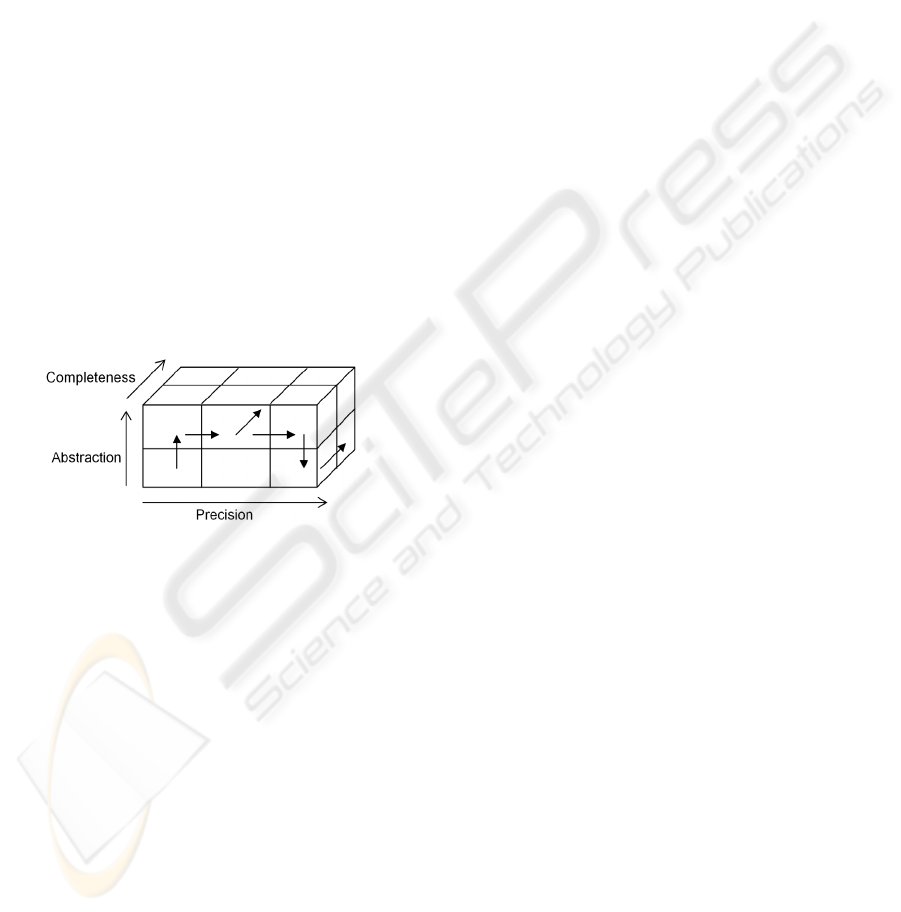
Figure 1: The Completeness – Precision – Abstraction 3D
space.
2.1 The 3D Space
The 3D space represented in Figure 1 guides method
engineers through a methodological frame to build
process metamodels for ISE. The three axes (Panet
and Letouche, 1994) help method engineers in the
selection of the concepts: completeness, precision
and abstraction. Completeness is the coverage of the
metamodel of one or more points of view (activity,
product, decision, context and strategy). Precision is
the level of detail of the metamodel. Abstraction is
the intentional and/or operational level of concern of
the metamodel. The intentional level represents the
objectives of the ISE process while the operational
level represents the actions required to concretize
these objectives. Method engineers will build their
process metamodels depending on these three axes:
each engineering activity on the Process Metamodel
Under Construction (PMUC) has for objective to:
extend the PMUC that corresponds to the
completeness axis, precise the PMUC that
corresponds to the precision axis or abstract (inv.
concretize) the PMUC that corresponds to the
abstraction axis.
2.2 The Conceptual Graph
The conceptual graph (Figure 2) is the base of our
method. It organises the recognized concepts for ISE
process metamodelling, representing the actual
knowledge base of the domain. The purpose of such
conceptual graph is to guide method engineers in the
Completeness – Precision – Abstraction 3D space
while selecting the concepts they need to represent
in their metamodels. The conceptual graph defines
the set of possibilities: it restrains method engineers
in the selection and the use of the defined concepts
only, in order to maintain the consistency of the
PMUC.
2.2.1 The Concepts
The concepts of the conceptual graph are used in
ISE processes and are usually represented in process
metamodels. The concepts of the graph represent
two types of elements:
- Classes that represent the main concepts
(concepts in bold in Figure 2) defined in the Process
Domain Metamodel and are linked to each other by
the completeness and abstraction relations. Those
concepts are Work Unit, Condition and Role
(activity point of view) (OMG. 2008; OPF;
OOSPICE; Australian Standard. 2004; ISO/IEC,
2007), Work Product (product point of view) (Harel,
1987; OMG, 2009; Humphrey and Kellner, 1989;
Finkelstein et al., 1990), Issue, Alternative,
Argument (decision point of view) (Kunz and Rittel,
1970; Potts and Bruns, 1988; Potts, 1989; Jarke et
al., 1992), Situation, Context, Intention (context
point of view) (Rolland et al., 1995) and Strategy
(strategy point of view) (Rolland et al., 1999).
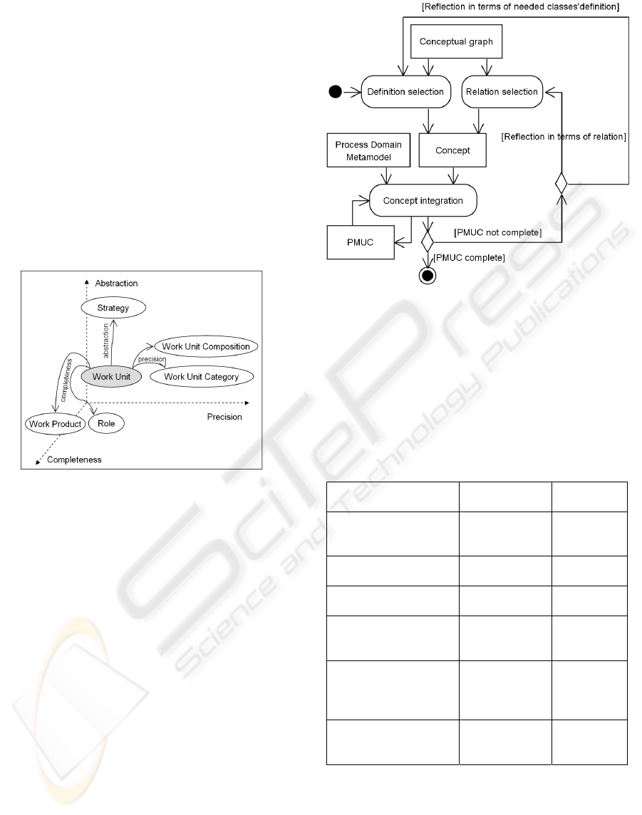
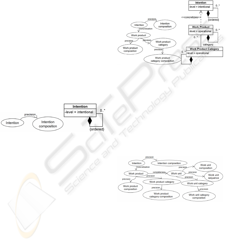
Figure 3 presents a close-up on a few of those. A
Work Unit represents an action that is executed
during the ISE process. A Work Product is
something that is produced, used or modified during
the ISE process and a Role is someone/thing that
carries out an action during the ISE process. A
Strategy represents how an intention is achieved.
- Classes that decompose the previous classes,
linked by the precision relation (secondary
concepts). For example, in Figure 3, the Work Unit
Category concept refines the Work Unit concept
A METHOD AND A TOOL BASED ON A CONCEPTUAL GRAPH FOR INFORMATION SYSTEMS ENGINEERING
PROCESSES
59
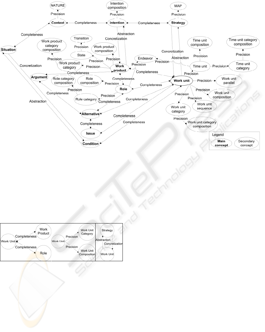
Figure 2: The conceptual graph.
to express the fact that there are different categories
of work unit, as activity or task for example. The
Work Unit Composition concept refines the Work
Unit concept to represent a Work Unit class with a
reflexive composition, to express that the “Design
components” activity is composed of the tasks
“Class design” and “Subsystem design” (Kruchten,
2000), for example.
Figure 3: Examples of the Completeness, Precision and
Abstraction relations.
2.2.2 The Relations
The relations represent conceptual links between
concepts in the Completeness – Precision –
Abstraction 3D space as presented in section 2.1.
The completeness relation links one concept to
another that extends it. This relation is symmetric,
non-transitive and non-reflexive. For example, in
Figure 3 (on the left), the Work Unit concept can be
completed by the Work Product and Role concepts.
As the Work Product concept can also be completed
by the Work Unit concept (symmetry), the
represented link is bidirectional.
The precision relation specifies that a concept
can be refined by another concept. Such relation is
non-symmetric, non-reflexive and non-transitive.
For example, the Work Unit concept can be refined
using the Work Unit Category or Work Unit
Composition concepts (but the Work Unit concept
does not refine the Work Unit Category concept –
non symmetry) (cf. Figure 3 in the centre).
The abstraction relation specifies that one
concept can be abstracted by another concept; it is
non-symmetric, non-reflexive and non-transitive.
For example, the Work Unit concept is abstracted by
the Strategy concept (cf. Figure 3 on the right). The
inverse relation of Abstraction is Concretization. We
can say that the Work Unit concept is the
concretization of the Strategy concept.
On the one hand, the relations help method
engineers selecting the concepts in the conceptual
graph and on the other hand, they assure the
coherency of the selected concepts. For example, the
Work Unit Category Composition concept can not
be selected before the Work Unit Category concept
has been selected (see Figure 2). The consistency of
the process metamodels produced is then ensured, as
the conceptual graph was designed in such a way as
the concepts were coherently linked to each others.
ENASE 2010 - International Conference on Evaluation of Novel Approaches to Software Engineering
60
2.2.3 Example
The conceptual graph in the Completeness –
Precision – Abstraction 3D space is dynamically
built: the perspective evolves depending on the node
the method engineer is considering. Figure 4 shows
a part of the 3D perspective that method engineers
would see from the Work Unit concept: if they want
to extend their PMUC, it will lead to the Work
Product and Role concepts thanks to the
completeness relation defined in the conceptual
graph. If they want to precise their PMUC, it will
lead to the Work Unit Category and Work Unit
Composition concepts, using the precision relation
and if they want to abstract it, it will lead to the
Strategy concept thanks to the abstraction relation.
Figure 4: Part of the perspective from the Work Unit
concept in the conceptual graph.
We now describe the method that uses the
conceptual graph to build process metamodels for
ISE.
3 THE METHOD
In this section, we present the method based on the
conceptual graph for building process metamodels
for ISE. The two-step method consists of: (i)
concepts selection within the conceptual graph, (ii)
concepts integration in the PMUC, according to the
Process Domain Metamodel. These two steps are
iterated until method engineers obtain the complete
process metamodel they need. In this paper, we
focus on the description of concepts selection.
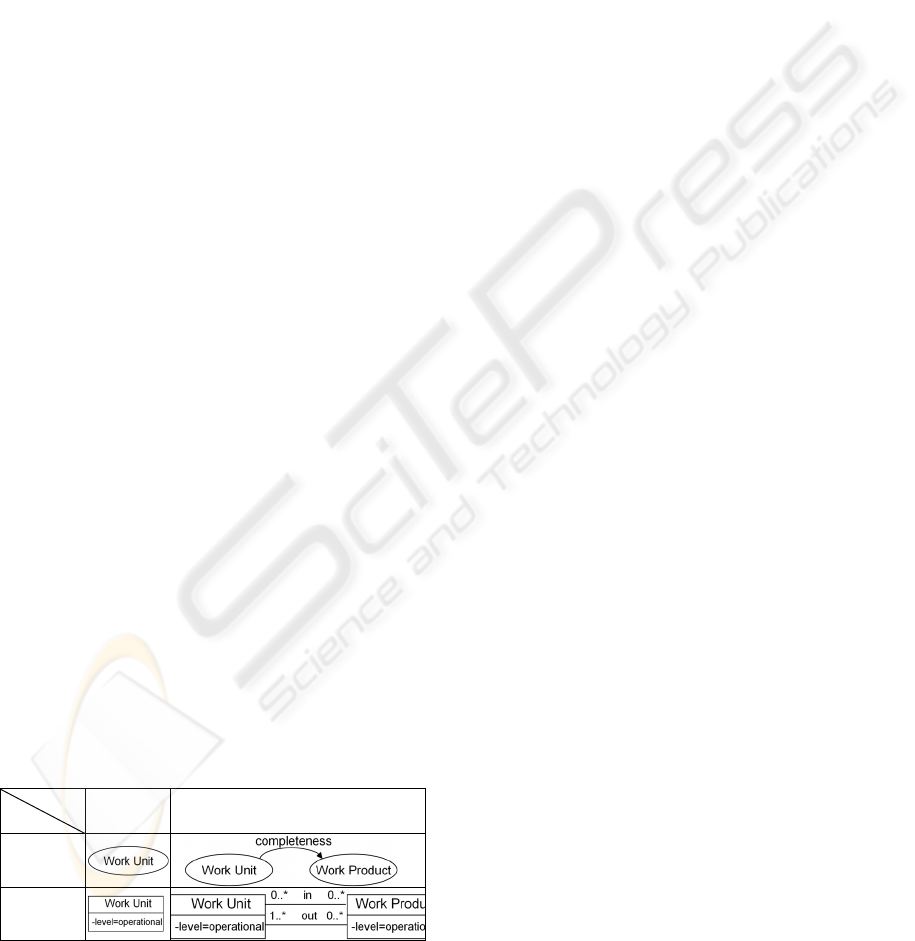
Figure 5 presents the method by an activity diagram;
it uses the conceptual graph described in Figure 2.
Figure 5: The method represented as an activity diagram.
The first activity of the process is Definition
selection that will lead to get a Concept. A definition
is composed of a short description, synonyms of the
concept and examples (see Table 1). It enables
method engineers to select definitions corresponding
to their needs. Each definition is associated to a
concept appearing as a node in the conceptual graph.
Table 1: Some definitions examples.
Description
Synonyms,
AKA, examples
Concept
Concept that represents
how an intention is
achieved
Tactics,
approach,
manner
Strategy
Objective of the ISE
process
Goal Intention
Task that is executed
during the ISE process
Activity, task,
work definition
Work Unit
Work Unit that is
composed of other work
units
Activity
composed of
tasks
Work Unit
composition
Something that is
produced, used or
modified by a work unit
during the ISE process
Product,
document,
model, program
Work Product
Someone/thing that
carries out a work unit
during the ISE process
Actor,
developer,
analyst, system
Role
Then, the corresponding concept is integrated in the
PMUC that is updated during the Concept
integration activity, based on the Process Domain
Metamodel. The integration activity is rather
complex: it has to take into account the different
types of concepts (main and secondary) and the
assembly of the classes into the PMUC. The main
A METHOD AND A TOOL BASED ON A CONCEPTUAL GRAPH FOR INFORMATION SYSTEMS ENGINEERING
PROCESSES
61
concepts of the Conceptual Graph correspond to
classes in the Process Domain Metamodel. The
secondary concepts correspond to design or business
patterns that are applied on the classes. The PMUC
is thus built by adding classes and applying patterns.
The integration process is described in detail in
(Hug, 2009).
Method engineers can then choose either to
continue the process or to stop it if the PMUC is
complete. If they choose to continue, they may
refine the PMUC in terms of concepts attainable
through relations with the previously integrated
concept (completeness, precision and abstraction
relations) or in terms of integration of classes thanks
to definitions. The Relation selection consists of
selecting one of the relations that starts from the
concept just integrated. For example, if the method
engineer just integrated the Work Unit concept to
his/her PMUC and if he/she wants to extend the
PMUC, he/she could select Role, Work product and
all the concepts linked through the completeness
relation to the Work Unit concept in the conceptual
graph. It works in the same way through the
precision and abstraction relations.
Table 2 presents a brief example of the
construction of a process metamodel. The first step
consists of selecting a concept thanks to its
definition. Depending on the need of the method
engineer at this stage, he/she chooses the definition
that corresponds to the Work Unit concept (first
loop/Selection). The concept integrated into the
PMUC corresponds to the Work Unit class (First
loop/Integration). In the second loop, the method
engineer might choose to think in terms of relations
to extend the PMUC. Thanks to the completeness
relation, he/she can select the Work Product concept.
The concept is integrated in the PMUC as the Work
Product class; the associations between the two
classes are also integrated. These relations are issued
from the Process Domain Metamodel, but we do not
detail this operation here.
Table 2: Example of the two first loops of the construction
of a process metamodel.
Loop
Step
1
st
loop 2
nd
loop
Selection
Integration
4 CASE STUDY
This section describes an extract of a case study of
the information system centre of Grenoble’s
University Hospital (http://www.chu-grenoble.fr/).
This case study has not a purpose of validating our
method but illustrating it. We specifically conducted
qualitative evaluations to validate the method (Hug
et al., 2010).
4.1 Requirements
The information system centre (ISC) manages
approximately forty different applications that need
to be regularly updated to meet new users’
requirements (medical assistants, hospital doctors
and administration staff).
The ISC managers want to model the ISE
processes to achieve a more rigorous project
management, defining a unified and optimal way to
manage projects regardless of the development team.
They also want to collect and reuse knowledge for a
more efficient production in terms of resources and
time use and therefore costs. A method engineer is
in charge of the study of the ISE processes and their
modelling. The method engineer in this case study is
one of the project managers of the ISC.
We have worked with this project manager who
determined the various aspects of the ISE processes
(this case study only presents an extract of the
problem):
- A part of the process is defined in terms of
goals and sub-goals; this part is intended primarily
for hospital services managers (services are for
example the surgical unit, the neurology or the
accounting department) who are more interested in
the results and impacts of new system functionalities
on their service (intentional part),
- The second part of the process is defined by
phases, activities and products produced during
these activities (operational part).
The problems met by the method engineer are
the following: how can he represent these concepts?
What are the existing models? Which models meet
these requirements? At the present time, these
representation choices are made difficult because of
the numerous existing process models and
metamodels, their lack of mutual complementarity
and the complexity to adapt them to specific needs
of organizations.
Our method enables the method engineer to
model the process metamodel that corresponds to the
information system centre ISE processes. The
method guides him through the selection of concepts
ENASE 2010 - International Conference on Evaluation of Novel Approaches to Software Engineering
62
he needs to represent and through their assembly in
order to create a specific process metamodel
including all the concepts at the intentional level
concerning the services managers and at the
operational level concerning the ISE process it-self.
4.2 Method Use
The first step of our method is the selection of a
concept by its definition. To select the first concept,
the method engineer must select one of the
definitions that correspond to the concepts he wants
to model. The definition “Goal or objective of the
ISE process” corresponds to the part of the process
defined in terms of goals. The engineer chooses this
definition and the corresponding Intention class is
integrated in the new PMUC. The method engineer
examines then the relations of the Intention concept
in the conceptual graph; the precision relation
permits him to select the Intention Composition
concept that will allow him to decompose the goals
into sub-goals. This concept is integrated in the
PMUC as a reflexive composition on the Intention
class. Figure 6 presents this part of the path in the
conceptual graph and the corresponding PMUC.
Figure 6: First part of the path in the conceptual graph and
the PMUC.
Then, the relation concretization starting from the
Intention concept in the conceptual graph allows the
method engineer to get the Work Product concept
that will represent the products produced during the
ISE process. The corresponding class is integrated in
the PMUC, as well as the “concretizes” dependency
linked to the Intention class.
In order to model the fact that a work product
can be composed of other work products (for
example, “Functional specifications” is composed of
“Simplified requirements” and “Actors diagram”),
the method engineer refines the Work Product
concept thanks to the Work Product Composition
concept. To specify that work products are of
different types (for example, “Functional
specifications” is a document and “Actor diagram”
is a UML diagram), the method engineer refines the
Work Product concept by the Work Product
Category concept. The Work Product Category class
is added into the PMUC. Similarly to what was done
with the Work Product, the engineer wants to
specify that a document is composed of UML
diagrams, texts and graphics. He refines the Work
Product Category concept by the Work Product
Category Composition concept. Figure 7 presents
the corresponding part of the path in the conceptual
graph and the corresponding PMUC.
Figure 7: Second part of the path in the conceptual graph
and the PMUC.
Thanks to the completeness relation, the method
engineer can extend the PMUC with the Work Unit
concept to represent activities and steps. The Work
Unit class and its associations “In” and “Out”
defined in the Process Domain Metamodel are
integrated to the PMUC. By using the precision
relation, the method engineer can refine the Work
Unit concept to represent the sequence and the
composition of work units, the work unit categories
and the composition of work unit categories. Figure
8 presents the complete path carried out in the
conceptual graph.
Figure 8: Complete path in the conceptual graph.
Figure 9 presents the final process metamodel
obtained thanks to the method. It models the classes
defined in the requirements and the associations
between them. The link between the classes of
intentional and operational level is represented by
the dependency link stereotyped as “concretizes”.
The abstraction level of each class is represented as
an attribute level.
A METHOD AND A TOOL BASED ON A CONCEPTUAL GRAPH FOR INFORMATION SYSTEMS ENGINEERING
PROCESSES
63
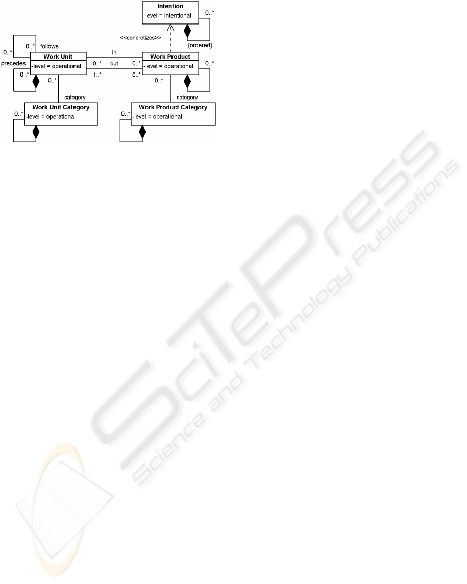
Figure 9: The final process metamodel.
The method engineer can then instantiate the
metamodel to represent the various ISE process
models of the ISC. Figure 10 is a partial instantiation
of the final process metamodel to represent the ISE
processes.
The method engineer wants to model the
intentions and sub-intentions of service managers.
One of the intentions of the service managers is to
know the level of impact of a new functionality and
the changes impacted on the services.
This can be represented as the object “Define the
level of impact of the change in the service”,
instance of the Intention class (see Figure 10). This
intention can be decomposed into two sub-
intentions. Service managers want to define the
impact of the change in the service organisation and
the persons that will be impacted by the change.
These estimations will be useful to define the costs
of the information systems change, as costs of
business process modifications. The operational
abstraction level of the process model represents the
detail of the “Pre-functional study” activity
composed of three steps. First, “Simplified
requirements specifications” produces the
“Simplified requirements” work product that is a
text. Second, the “Constitution of business terms
glossary” step produces a glossary that is a text.
Finally, “Actors modelling” produces a UML
diagram “Actors diagram”. The whole work
products produced during the Pre-functional study
forms a document called “Functional specifications”
(not represented in Figure 10).
The two sub-intentions “Define the impact on the
service organization” and “Define the persons who
are impacted by the change” are concretized by the
“Simplified requirements” and “Actors Diagram”
work products.
The process model represented as an object
diagram is not easy and quickly understandable. Our
method suggests a graphical representation
(formalism) depending on the concepts selected in
the process metamodel. For example, if concepts of
the operational level as work unit and work product
are defined in the metamodel, the method will
propose to use activity diagrams (OMG, 2009). If
intentions and strategies are used, the method will
propose the MAP formalism (Rolland et al., 1999),
if there are only intentions, the KAOS formalism
(Objectiver, 2007) will be proposed.
Figure 11 shows how we can represent the
intentions and sub-intentions of the intentional level
defined in Figure 10 using the KAOS formalism.
The intentions and sub-intentions are represented as
parallelograms. The composition is modelled thanks
to a circle.
Figure 12 presents the concepts of the
operational level defined in Figure 10 as an activity
diagram. The activities and steps are represented
with rounded rectangles. All the work products are
represented by rectangles. Stereotypes are used to
specify the category of the work products.
However the “concretizes” dependencies are not
shown in the figures, there are defined between the
different work products and intentions of the models
and method engineer, service managers or project
managers can switch from one level to another.
5 DISCUSSION
Our proposition offers method engineers to build
process metamodels for ISE depending on the needs,
the specificities, the context or the situation of the
projects or organisations. Our purpose differs from
Situational Method Engineering, as it aims at
defining information systems development methods
by reusing and assembling different existing method
fragments (Ralyté and Rolland, 2001), but it is set in
the same trend of situational engineering. We may
name our domain SPME (Situational Process
Metamodelling Engineering).
Let us note that we do not reconsider the existing
process metamodels. They all play a part in ISE
processes and have their legitimacy. However, they
do not define their concepts complementarity in
respect to the other process metamodels. Our
proposition does not consist of yet another process
metamodel, but it proposes a method allowing
method engineers to build process metamodels
including complementarity between the concepts.
Our method uses some part of the existing
process metamodels. Therefore, method engineers
can reuse knowledge they acquired from their
experience in ISE process metamodelling.
ENASE 2010 - International Conference on Evaluation of Novel Approaches to Software Engineering
64
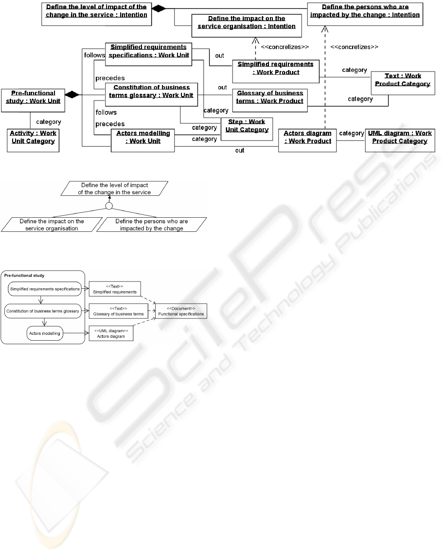
Figure 10: The process model represented as an object diagram.
Figure 11: Intentions and sub-intentions in the ISE process
of the case study.
Figure 12: An activity of the ISE process of the case study.
There lies the real contrast between our proposal and
currently available process models, such as RUP
(Kruchten, 2000) or SCRUM (Schwaber and Beedle,
2001), process models that are hardly adaptable.
Applying these, method engineers must follow them
as described and have a little or no mean of
customization. Our method, on the other hand,
proposes method engineers to instantiate process
models according to their needs from process
metamodels they have defined themselves but still
using widely accepted concepts and formalism of
ISE process models.
The existing process metamodels (Hug et al.,
2009) are also fixed. They do not allow method
engineers to extend them or customize them to add
concepts they would need in their process models.
Their use is therefore limited as they do not provide
all needed concepts. For example, adding the
intention concept to the RUP model would be
difficult as it is not define in the RUP metamodel.
Using it without defining it in the metamodel could
lead to misuses and the relations with the other
concepts would not be defined.
Finally, new process metamodels as ISO/IEC
24744 (ISO/IEC, 2007) are more flexible and
provide more concepts than previous process
metamodels thanks to metamodelling mechanisms as
the Powertype. However, the strategy, intention and
decision concepts are not taken into account here.
To conclude, we can say that our method allows
more flexibility, more personalized adaptation and
allows building process metamodels with less
limitation than the existing one.
6 PROMISE
In this section, we present ProMISE (Process
Metamodelling for Information Systems
Engineering), a tool that supports our method.
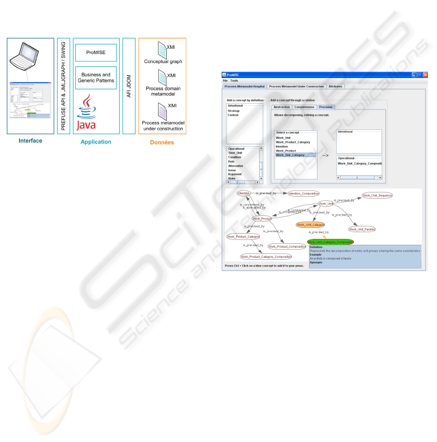
6.1 Technical Architecture
Figure 13 describes the architecture of ProMISE.
The tool has been built using Java. The two main
supports of the method, the conceptual graph and the
Process Domain Metamodel (Hug et al., 2008a,
2008c, 2009), are defined independently from the
tool in XMI files. XMI (OMG. 2007) is a standard
format that allows storing UML diagrams as
structured text files. The main benefit of having the
supports outside the tool is to permit more flexibility
and scalability as the guiding will be generated
thanks to the conceptual graph file and not the tool
it-self. The guiding evolves as the conceptual graph
evolves.
Method engineers can interact with a visual
conceptual graph, thanks to Prefuse (Prefuse. 2009).
A METHOD AND A TOOL BASED ON A CONCEPTUAL GRAPH FOR INFORMATION SYSTEMS ENGINEERING
PROCESSES
65
Prefuse is a powerful toolkit for creating rich
interactive data visualizations, such as graph.
The Process Metamodel Under Construction,
PMUC, is displayed as a UML class diagram using
the API UMLJGraph (UMLJGraph. 2005) that
allows displaying UML diagrams in Java.
The PMUC can be exported as an XMI file. This
allows method engineers to import their process
metamodels in any CASE tool, to instantiate them
for example.
The imports and exports are done thanks to
JDom (JDOM. 2007), a Java API able to read and
write both XML and XMI files.
Figure 13: Architecture of the ProMISE tool.
6.2 General Organisation
The tool allows method engineers to build process
metamodels through the use of the concepts
definition and the relations. Figure 14 presents a
global view of the interface. It is composed of three
tabs:
– The first tab (here called “Process-Metamodel-
Hospital) allows method engineers to build their
PMUC for a particular organization or project
through the use of the definitions and the relations.
– The second tab, “Process Metamodel Under
Construction”, allows method engineers to view
their PMUC as a UML class diagram.
– The third tab, “Attributes”, allows method
engineers to add attributes to their PMUC classes,
we will not detail this functionality here.
6.3 Construction of the PMUC
The first tab that allows the construction of the
PMUC is decomposed in two parts:
– The top part of the interface permits to select
concepts by definition or by relation. Concepts are
displayed according to their abstraction level which
facilitates their selection. The definition, examples
and synonyms of each concept can be seen by mouse
over.
Each relation (completeness, precision, abstraction)
is represented by a tab. By selecting one tab, the
concepts that can be integrated through the
corresponding relation are displayed in the lists. For
example, in Figure 14, the Precision tab is selected.
Work Unit Category is a concept that can be refined;
this allows selecting the Work Unit Category
Composition concept.
– The lower part of the interface shows the
conceptual graph with the already integrated
concepts in the PMUC and the concepts that can be
reached by the relations and that can be integrated in
the PMUC (Work Unit Category Composition in
Figure 14). By selecting a relation tab, the
conceptual graph is updated with the concepts that
can be integrated.
Figure 14: Interface of the ProMISE tool.
7 CONCLUSIONS
In this paper, we present a method that allows
method engineers to build process metamodels for
ISE. The method is based on two steps: (i) the
selection of concepts meeting the specificities and
constraints of the projects or organizations, using a
conceptual graph to help the concepts selection in a
completeness – precision – abstraction 3D space; (ii)
the integration of the concepts permits building an
adapted process metamodel called PMUC. We
present our method as an activity diagram. We have
to detail further the integration step, as it is a
complex task.
A tool, ProMISE, has been implemented to allow
method engineers to build process metamodels
ENASE 2010 - International Conference on Evaluation of Novel Approaches to Software Engineering
66

according to our method. Further step is to allow the
instantiation of the process metamodels until the
monitoring of particular information systems
engineering projects.
The Process Domain Metamodel may evolve,
with the publication by the community of new
process models and metamodels for ISE. The
conceptual graph will also evolve, in order to
propose method engineers the largest choice of
possibilities taking into account the latest evolutions
in terms of ISE process metamodelling.
Another part of perspectives concerns the
formalism that method engineers should use to
represent the process models instantiated from the
metamodels produced by this method. It would be
useful to guide method engineers in the use of such
or such formalism, depending on the concepts
selected in their PMUC.
REFERENCES
Australian Standard. 2004. Standard Metamodel for
Software Development Methodologies. AS 4651 –
2004.
Beck, K. 1999. Extreme Programming Explained:
Embrace Change. Addison-Wesley Professional,
Longman Publishing Co., Inc. Boston, Massachusetts.
Boehm, B. 1986. A spiral model of software development
and enhancement. SIGSOFT Soft. Eng. Notes, vol. 11,
n°4, 14-24.
Finkelstein, A., Kramer, J., Goedicke, M. 1990. ViewPoint
oriented software development. 3
rd
International
Workshop on Software Engineering and Its
Applications, 374-384.
Harel, D. 1987. Statecharts: A Visual Formulation for
Complex Systems. Science of Computer
Programming, vol. 8, n°3, 231-274.
Hug, C., Front, A., Rieu, D. 2008a. A Process Engineering
Method Based on a Process domain Model and
Patterns. MoDISE’08 held in conjunction with
CAiSE'08, 126-137.
Hug, C., Front, A., Rieu, D. 2008b. Ingénierie des
processus. Une approche à base de patrons. Revue
RSTI, série ISI. Vol. 13, n°4, Hermès, France, 11-34.
Hug, C., Front, A., Rieu, D. 2008c. Process Engineering
Method Based on Ontology and Patterns. ICSOFT’08,
29-36.
Hug, C., Front, A., Rieu, D., Henderson-Sellers, B. 2009.
A Method to build Information Systems Engineering
Process Metamodels. J. Syst. Software, vol. 82, n°10,
1730-1742.
Hug, C., 2009. Méthode, modèles et outil pour la méta-
modélisation des processus d’ingénierie de systèmes
d’information. Joseph Fourier- Grenoble I University,
PhD Thesis.
Hug, C., Mandran, N., Front, A., Rieu, D. 2010.
Qualitative Evaluation of a Method for Information
Systems Engineering Processes. RCIS’2010.
Humphrey, W. S., Kellner, M. I. 1989. Software process
modeling: principles of entity process models. ICSE
'89I, ACM, New York, NY, 331-342.
ISO/IEC. 2007. 24744 Software Engineering - Metamodel
for Development Methodologies.
Jarke, M., Mylopoulos, J., Schmidt, J.W., Vassiliou, Y.
1992. DAIDA: An Environment for Evolving
Information Systems. ACM Trans. on Inf. Sys., vol. 10,
n°1, 1-50.
JDOM. 2007. http://www.jdom.org/
Kruchten, P. 2000. The Rational Unified Process: An
Introduction. Addison-Wesley, Longman Publishing,
Co., Inc. Boston, Massachusetts.
Kunz, W., Rittel, H.W.J. 1970. Issues as elements of
information systems. Working Paper 131, Heidelberg-
Berkeley.
Objectiver. 2007. A KAOS tutorial. Respect-It.
OMG. 2007. MOF 2.0 / XMI Mapping Specification.
Version 2.1.1.
OMG. 2008. Software Process Engineering Meta-Model.
Version 2.0.
OMG. 2009. Unified Modeling Language: Superstructure.
Version 2.2.
OOSPICE, Software Process Improvement and Capability
Determination for Object- Oriented/ Component-
Based Software Development,
http://www.oospice.com
Open Process Framework, http://www.opfro.org
Panet, G., Letouche, R. 1994. Merise/2 Modèles et
techniques Merise Avancés. Les Editions
d’Organisation, Paris.
Potts, C. 1989. A generic model for representing design
methods. ICSE’89, IEEE Com. Soc./ ACM Press, 217-
226.
Potts, C., Bruns, G. 1988. Recording the Reasons for
Design Decisions. ICSE’88, IEEE Com. Soc. Press,
418-427.
Prefuse. 2009. http://prefuse.org/
Ralyté J., Rolland, C. 2001. An Assembly Process Model
for Method Engineering. CAiSE 2001, LNCS, vol.
2068, 267-283. Springer-Verlag, London.
Rolland, C., Prakash, N., Benjamen, A. 1999. A Multi-
Model View of Process Modelling. Requirements
Engineering, vol. 4, n°4, 169-187.
Rolland, C., Souveyet, C., Moreno, M. 1995. An
Approach for defining ways-of-working. Information
System Journal, vol. 20, n°4, 337-359.
Royce, W. W. 1987. Managing the development of large
software systems: concepts and techniques. ICSE’87,
IEEE Com. Soc. Press, 328-338.
Schwaber, K., Beedle, M. 2001. Agile Software
Development with SCRUM. Prentice Hall, Upper
Saddle River, New Jersey.
UMLJGraph. 2005. http://umljgraph.sourceforge.net/
A METHOD AND A TOOL BASED ON A CONCEPTUAL GRAPH FOR INFORMATION SYSTEMS ENGINEERING
PROCESSES
67
