
Towards a Multi-camera Mouse-replacement Interface
John Magee, Zheng Wu, Harshith Chennamaneni, Samuel Epstein
Diane H. Theriault and Margrit Betke
Computer Science Department, Boston University
111 Cummington St, Boston, MA 02215 U.S.A.
Abstract. We present our efforts towards a multi-camera mouse-replacement
system for computer users with severe motion impairments. We have worked
with individuals with cerebral palsy or multiple sclerosis who use a publicly-
available interface that tracks the user’s head movements with a single video cam-
era and translates them into mouse pointer coordinates on the screen. To address
the problem that the interface can lose track of the user’s facial feature due to
occlusion or spastic movements, we started to develop a multi-camera interface.
Our multi-camera capture system can record synchronized images from multiple
cameras and automatically analyze the camera arrangement. We recorded 15 sub-
jects while they were conducting a hands-free interaction experiment. We recon-
structed via stereoscopy the three-dimensional movement trajectories of various
facial features. Our analysis shows that single-camera interfaces based on two-
dimensional feature tracking neglect to take into account the substantial feature
movement in the third dimension.
1 Introduction
Camera-based human-computer interaction via analysis of head movement has been
studied for many years (e.g. [1–3]). Early work has typically focused on single-camera
interfaces for entertainment, control of electronic devices (e.g., the remote control of
a TV), and support of automated speech analysis. Camera-based human-computer in-
teraction systems that serve as assistive communication tools have had an enormous
impact on the lives of individuals with severe motion impairments [4,5]. These systems
function as mouse-replacement software that allow users to control a computer mouse
pointer with head movements. The movements of the user’s head [6], nose [4,5,7] or
other features [4] are converted into movements of the mouse pointer on the screen. To
mimic the functionality of a left mouse click, a mouse replacement system typically
evaluates the length of time that the pointer dwells over an icon, button, or menu item
(or its surrounding region) and then issues a selection command.
Currently available video-based mouse-replacement systems for people with severe
disabilities process the input video captured by a single camera. We propose a multi-
camera approach to alleviate the problems with track failures that such systems en-
counter in practice. Track failures occur when facial features become occluded during
tracking, for example, when extreme head rotations result in self-occlusion of the fea-
ture. Track failures also occur due to involuntary rapid movements of users with spastic
cerebral palsy. In addition, multiple camera systems may be able to use information
Magee J., Wu Z., Chennamaneni H., Epstein S., H. Theriault D. and Betke M.
Towards a Multi-camera Mouse-replacement Interface.
DOI: 10.5220/0003001700330042
In Proceedings of the 10th International Workshop on Pattern Recognition in Information Systems (ICEIS 2010), page
ISBN: 978-989-8425-14-0
Copyright
c
2010 by SCITEPRESS – Science and Technology Publications, Lda. All rights reserved
about the user’s motion in three dimensions to provide better control of the mouse
pointer.
Data from more than one camera allows for use of a confidence measure computed
from detecting and tracking the objects in different images and evaluating if they are
consistent [8]. This may alleviate the problem of feature loss due to occlusion. For
example, when the feature movesout of the field of vision of one of the cameras (the left
nostril is occluded because the user turns left), the tracking of the feature is continued
in another camera’s field of view. We propose a camera placement that ensures that the
fields of views of the cameras partially overlap. With this setup, if the feature is lost in
one camera view, the tracker can use another camera view to continue tracking.
To facilitate research on multi-camera assistive technology, we developed a system
that allows processing of images that are captured simultaneously from multiple cam-
eras. Our Multi-Camera Capture (MCC) system provides the general framework for
working with n cameras and has been tested using up to four cameras simultaneously.
The scope of the current project is limited to the following contributions:
1. We provide a software system that enables images to be recorded from multiple
cameras.
2. We createda newdatabase of videos of 15 subjects that are simultaneously recorded
from three camera views while they were performing an interaction task.
3. We present a preliminary stereoscopic analysis of the three-dimensional trajectories
of facial features during interaction experiments.
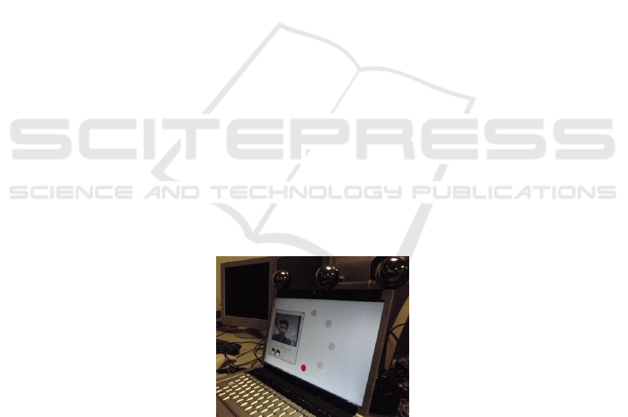
Our system uses inexpensivewebcams, arranged on a desk in a typical human-computer
interaction environment (Fig. 1), in contrast to expensive calibrated multi-camera cap-
ture systems in controlled laboratory environments. There is a need in the computer
vision community to create data sets with which 3D face tracking systems can be eval-
uated [9]. This applies both to systems that use multiple cameras [9–12] or a single
camera [13]. We hope that other computer-vision research groups will make use of our
capture system and data, and help move forward the research on reliable communication
systems for people with disabilities.
Fig.1. A setup of the Multi Camera Capture system with three cameras. The cameras are the
three silver-colored spheres on top of the laptop display.
34

2 Methods
Our system divided into three modules, a multi-camera capturing module that provides
temporal calibration, a module that evaluates the geometric relationship between the
cameras and provides spatial calibration, and a third module that provides stereoscopic
reconstruction of three-dimensional (3D) coordinates.
The first module, the Multi Camera Capture (MCC) program, records images from
the cameras simultaneously and stores them. The second module performs camera cal-
ibration, that is to recover each camera’s focal length, principal point, radial distortion
coefficients (the “intrinsic parameters,” which make up the camera matrix K) and spa-
tial relationship between objects and cameras (the “extrinsic parameters” of rotation
R and translation t). To estimate the intrinsic parameters, we use a planar calibration
object chessboard with known physical size (Fig. 2). The use of a planar object allows
us to focus on just two coordinates of each three-dimensional object point and deter-
mine the homography H, which maps points (X, Y, 1)
T
on the object plane to points
(x, y, 1)
T
on the image plane, i.e., (x, y, 1)
T
= H · (X, Y, 1)
T
. We are interested in
estimating H because it encodes the camera matrix K, the rotation matrix R, and the
translation vector t:
H = s K[r
1
r
2
t], (1)
where s is a scale factor and r
1
and r
2
are first two columns of the rotation matrix R.
With a sufficient number of pairs of points on the chessboard and their correspond-
ing image points, the matrix H can be estimated using Singular Value Decomposition
(SVD). With several images of the chessboard, oriented differently towards the camera,
we can estimate multiple homography matrices H
i
for the same camera matrix K. The
fact that vectors r
1
and r
2
are orthonormal provides additional constraints. Matrix K is
then estimated by solving a system of linear equations [14].
The intrinsic parameters of each camera, given by matrix K, only need to be esti-
mated once and can then be used for stereoscopic reconstruction by our multi-camera
capture system. To estimate the extrinsic parameters, we reuse the chessboard images
to estimate the “fundamental matrix” that relates the coordinates of a feature in the
image of one camera to the coordinates of the feature in the corresponding image of an-
other camera. The program automatically estimates the positions of the corresponding
points of pattern corners in each camera view. In particular, given the two-dimensional
coordinates q
i
= (x
i
, y
i
)
T
of a point in the ith camera view and the two-dimensional
coordinates q
j
= (x
j
, y
j
)
T
of a corresponding point in the jth camera view, the funda-
mental matrix relates the two via the equation
q
T
i
F
ij
q
j
= 0. (2)
The entries of the matrix F
ij
can be estimated using the 8-point algorithm [15], whose
name comes from the number of corresponding point pairs (q
i
, q
j
) that are used as
input. Matrix F
ij
can also be estimated by using significantly more point pairs, incor-
porating the 8-point algorithm into a RANSAC framework [16]. It labels point pairs
that do not agree with the most probable result as outliers. These point pairs may have
been incorrectly identified as corresponding points. RANSAC is a non-deterministic al-
gorithm that iterates through the possibilities of matrix entries until a desired level of
35
accuracy is achieved. The desired level of accuracy is specified as a probability that the
computed matrix is the most likely among all possible matrices. The set of point pairs
used as input to the RANSAC algorithm may yield a number of all possible subsets of
8 corresponding points that is so large (e.g., order of millions) that it is computationally
expensive to compute all matrices exhaustively.
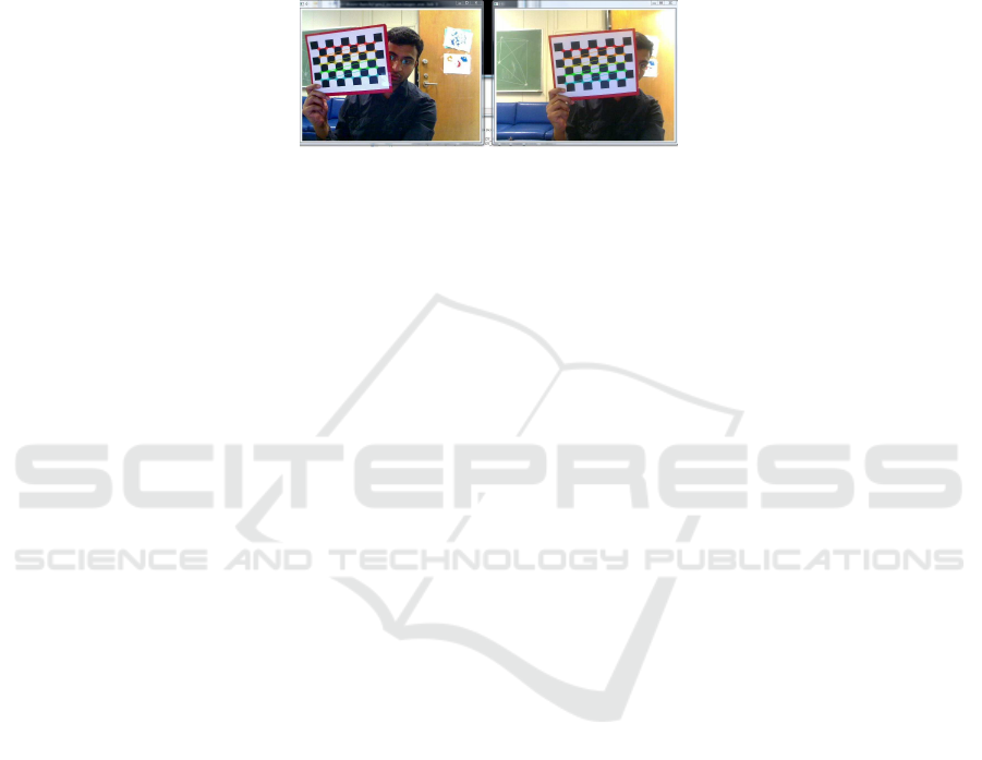
Fig.2. A screenshot of the Multi Camera Capture system while it is used to record images simul-
taneously from two cameras in an experiment. In the field of view of the two cameras is a board
with a checker pattern, which is used for spatial calibration of the cameras.
Our spatial calibration module calls the RANSAC method on 40 point pairs and
uses an OpenCV function [14] to estimate the entries of the fundamental matrix. Our
method uses a 99%-probability level as the desired accuracy threshold. If this threshold
yields a number of outlier pairs that exceeds 12 (i.e., 12/40 ≈ 30% of the pairs), the
points collected for stereo calibration are deemed to be insufficiently accurate, and a
new calibration process is run.
Once the fundamental matrix F
ij
is determined, we can estimate the “essential ma-
trix” E
ij
that encodes the absolute position and orientation of the two cameras:
E
ij
= K
T
j
F
ij
K
i
. (3)
To obtain the coordinates of corresponding points in three-dimensional world coordi-
nates, we need to estimate the projection matrix P = K[R |t] of each camera. We
assign the origin of the world-coordinate system to the center of projection of our first
camera, which means that P
1
= K
1
[I |0]. The projection matrices P
j
of the other
cameras can then be constructed through SVD factorization of the essential matrices
E
1j
[15]. The projection matrices are stored by our calibration module and used for 3D
reconstruction through triangulation by the third module of our system.
Our program relies on the known calibration device, the chessboard, for the calibra-
tion procedure. As an alternative, we have tracked distinctive features such as a human
eye through several frames of each camera and used feature correspondences to per-
form self-calibration [15], that is, to estimate both intrinsic and extrinsic parameters for
all cameras at the same time. The unknown scale can be estimated by measuring the
physical distance between tracked features, e.g., the distance between a person’s eyes.
3 Experiments and Results
We used a three-camera version of our multi-camera interaction system to record 15
subjects while they were conducting a human-computer interaction experiment. The
36
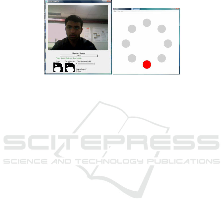
Fig.3. Left: A screenshot of the Camera Mouse interface used in the experiments. Right: A
screenshot of the ClickTester program. The user was instructed to move the mouse pointer into the
target circle, highlighted in red, with head movements that were detected by the Camera Mouse.
The ClickTester program presented a sequence of target circles to the user that was designed so
that significant mouse pointer movements and changes in movement directions were required.
group of subjects included 8 men and 7 women. Most subjects had dark hair. Two sub-
jects wore glasses. For each subject, we recorded three image sequences using three
Logitech Orbit MP cameras (Fig. 1). The cameras were not radiometrically calibrated
and each used automatic gain control. The recordings were synchronized by our tem-
poral calibration module so that temporally corresponding images were identifiable.
Prior to the hands-free human-computer interaction experiment, the fundamental
matrices for all pairs of cameras were estimated and stored using our spatial calibration
module. We numbered the cameras from left to right starting with 0. Our system then
provided an estimate of the fundamentalmatrices F
01
, F
12
and F
02
that relate the image
coordinatesof cameras 0 and 1, 1 and 2, and 0 and 2, respectively.The spatial calibration
module was executed before every subject test was performed in order to ensure spatial
calibration via the three fundamental matrices. The camera positions were not disturbed
during the recording.
We used the publicly-available assistive technology “Camera Mouse” [4,17] (Fig. 3
left), which is a single-camera mouse-replacement system for people with severe mo-
tion impairments. We initialized the Camera Mouse using the standard mouse by se-
lecting a facial feature (eyebrow corner) to track. The region around the corner of an
eyebrow contains significant brightness changes, which makes it a reliable feature to
track.
Our system recorded three image streams while the test subjects were moving their
heads significantly (Fig. 4). We developed test software, called “Click Tester,” that pro-
vided a movement protocol and ensured that all subjects were recorded with various
head positions and orientations.
The ClickTester software displays eight circles on the screen, one of which is high-
lighted (see Fig. 3, right). In our experiments, the subject was asked to move the mouse
pointer onto the highlighted circle using the Camera Mouse. When the subject had
37
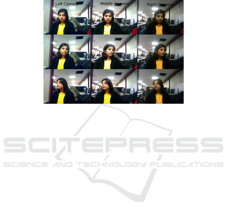
Fig.4. Images collected at different points in time during the human-computer interaction exper-
iment. Each row shows the three simultaneously-recorded frames as captured by the left, center,
and right cameras. The subject’s head orientation differs significantly from row to row and the
subject’s left eye is occluded in the right camera view in the second row. Similarly, the subject’s
right eye is occluded in the left camera view in the third row. The lack of radiometrical calibration
of the cameras and the use of separate automated gain controls resulted in images with different
intensity levels. This is particularly noticeable in the images recorded by the right camera, which
are darker than the images recorded by the left and center cameras.
moved the mouse pointer to the highlighted circle, a new circle was highlighted. The
subject was asked to repeat the process until all circles were visited. The software was
designed as a means to simulate a realistic use of a camera-based mouse-replacement
system that involved significant head motions. It also records the trajectory of the mouse
pointer for further analysis.
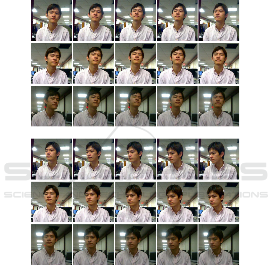
Among the head motions that the subjects performed was a gesture in which the
subjects moved their heads first upwards and then diagonally to the lower left. One of
the subjects performing this gesture is shown in Fig. 5. His gesture lasted about three
seconds, which corresponded to 17 frames. Ten of these 17 frames, as recorded by each
of the three cameras, are shown in Fig. 5. We reconstructed the 3D positions of the
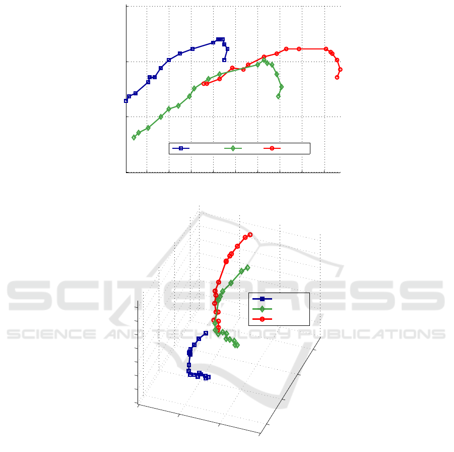
outer corners of the subject’s eyes and his nose tip during the head gesture. The 3D
trajectories of the three features are shown in Fig. 6. We placed the 3D scene coordinate
system so that its x and y axes were aligned with the image plane of the left camera and
the z axis was normal to and pointed away from the image plane. The origin of the 3D
scene coordinate system was placed at the location of the nose tip in the first frame of
the left camera view.
During the gesture, the features moved on average 18.5 cm in the 3D scene. It
is noteworthy that, during the head gesture, the features moved 4.6 cm in the direc-
tion away from the left camera when the user directed the mouse pointer to the top
38

of the computer screen. The features then moved back 3.0 cm towards the left camera
when the user moved the mouse pointer to a region near the left corner of the screen.
This component of a user’s head movement cannot be taken into account by a single-
camera mouse-replacement interface that is based on two-dimensional tracking of the
feature projected into the image plane. The conversion from image-feature coordinates
to mouse-pointer screen coordinates is typically implemented as a linear transforma-
tion in single-camera mouse-replacement systems. This means that the user is required
to exert more efforts to move the mouse pointer in the outer regions of the computer
screen than to move it within the center region of the screen. This may be particularly
significant for individuals who have very limited head movements. It motivates imple-
mentations of nonlinear transfer functions [6], for example, based on distance to the
center of the screen.
4 Discussion and Conclusions
We presented our research efforts towards developing a multi-camera mouse-replace-
ment system for computer users with severe motion impairments. We have several
years of experience working with individuals who use the “Camera Mouse,” a publicly-
available interface system that tracks the computer user’s head movements with a single
video camera and translates them into the movements of the mouse pointer on the com-
puter screen. To address the problem that the Camera Mouse can lose track of facial
features due to occlusion or spastic movements, we started to develop a multi-camera
interface that provides (1) redundant input so that there is not a single point of tracking
failure and (2) additional stereoscopic information to improve system reliability.
Our current multi-camera capture system can record synchronized images from
multiple cameras showing different but, as typically desired, overlapping views of the
same scene. Our system also automatically analyzes the geometry of the camera ar-
rangement. It uses inexpensive webcams that can be placed on a desk in a typical
human-computer interaction arrangement.
We used a three-camera version of our system to record 15 subjects while they were
conducting a hands-free human-computer interaction experiment in real time. For this
experiment, we developed a testing program that guided the subjects in making various
head movements that resulted in significant mouse pointer movements and changes in
movement directions. For each subject, we recorded three image sequences that were
synchronized so that corresponding images were identifiable.
Our system provided the information about the geometry of any pair of cameras rel-
ative to one another. We reconstructed via stereoscopy the three-dimensional movement
trajectories of various features such as the eyes and nose tip. Our analysis shows that
single-camera interfaces based on two-dimensional feature tracking neglect to take into
account the substantial feature movement in the third dimension.
39
1 3 5 7 8
10 12 14 16 17
Fig.5. Cropped images of a user during our human-computer interaction experiment with the
ClickTester program. Each column shows simultaneously recorded images from the left, center,
and right cameras with the corresponding frame number (time stamp) on top. During the exper-
iment, the user first selected a target circle at the top of the screen, which resulted in a raising
of his head. He then moved the mouse pointer to a target circle near the lower left corner of the
screen, which resulted in a turning and lowering of his head.
40
30 32 34 36 38 40 42 44 46
15
20
25
30
X−Axis (cm)
Y−Axis (cm)
Right Eye Nose Left Eye
1
5
3
7
8
10
12
14
16
17
17
16
14
12
8
7
5
3
1
1
3
8
10
12
14
17
16
7
5
10
30
35
40
45
15
20
25
30
−12
−10
−8
−6
−4
−2
0
2
X−Axis (cm)
Y−Axis (cm)
Z−Axis Depth (cm)
Right Eye
Nose
Left Eye
16
17
16
14
12
10
8
7
5
1
3
1
8
10
12
14
17
1
3
5
7
8
10
12
17
16
14
3
5
7
Fig.6. Reconstructed 3D feature trajectories. Numbers indicate time stamps. Top: 3D points in
the x-y plane that is parallel to the left camera. Bottom: This viewing angle shows the significant
feature movement in the z direction, first away and then towards the camera.
Acknowledgements
We would like to thank the human subjects who spared time from their busy schedules
to participate in the experiments. Funding for this work was provided by the National
Science Foundation, HCC grant IIS-0713229.
41

References
1. A. H. Gee and R. Cipolla. Tracking faces. In R. Cipolla and A. Pentland, editors, Computer
Vision for Human-Machine Interaction, pages 113–122. Cambridge University Press, 1998.
2. W. T. Freeman, D. Anderson, P. Beardsley, C. Dodge, H. Kage, K. Kyuma, Y. Miyake,
M. Roth, K. Tanaka, C. Weissman, and W. Yerazunis. Computer vision for interactive com-
puter graphics. IEEE Computer Graphics and Applications, 18(3):42–53, May 1998.
3. M. Turk and R. George. Perceptual user interfaces. Comm. of the ACM, 43(3), 2000.
4. M. Betke, J. Gips, and P. Fleming. The camera mouse: Visual tracking of body features to
provide computer access for people with severe disabilities. IEEE Transactions on Neural
Systems and Rehabilitation Engineering, 10(1):1–10, 2002.
5. J. Varona, C. Manresa-Yee, and F. J. Perales. Hands-free vision-based interface for computer
accessibility. Journal of Network and Computer Applications, 31(4):357–374, 2008.
6. R. Kjeldsen. Improvements in vision-based pointer control. In 8th International ACM
SIGACCESS Conference on Computers and accessibility (Assets ’06), pages 189–196, 2006.
7. D. O. Gorodnichy and G. Roth. Nouse ’use your nose as a mouse’ perceptual vision tech-
nology for hands-free games and interfaces. Image and Vision Computing, 22(12):931–942,
2004.
8. E. A. Cansizoglu and M. Betke. An information fusion approach for multiview feature
tracking. In 20th International Conference on Pattern Recognition (ICPR 2010), Istanbul,
Turkey, 2010. 4 pp.
9. T. K. Marks, J. R. Hershey, and J. R. Movellan. Tracking motion, deformation, and texture
using conditionally Gaussian processes. IEEE Transactions on PatternAnalysis and Machine
Intelligence, 32(2):348–363, 2010.
10. C. John, U. Schwanecke, and H. Regenbrecht. Real-time volumetric reconstruction and
tracking of hands and face as a user interface for virtual environments. In VR 2009: IEEE
Virtual Reality Conference, pages 241–242, 2009.
11. M. R¨atsch, C. Blumer, G. Teschke, and T. Vetter. Coarse-to-fine particle filters for multi-
object human computer interaction. In IEEE International Workshop on Intelligent Data Ac-
quisition and Advanced Computing Systems: Technology and Applications (IDAACS 2009),
pages 440–445, September 2009.
12. K. Sidorov, Y. Hicks, D. Marshall, S. Sanei, and J. Chambers. Real time multi camera 3D
tracking system. In 3rd European Conference on Visual Media Production (CVMP 2006),
page 191, London, UK, 2006.
13. F. Dornaika and B. Raducanu. Three-dimensional face pose detection and tracking using
monocular videos: Tool and application. IEEE Transactions on Systems, Man, and Cyber-
netics, Part B: Cybernetics, 39(4):935–944, 2009.
14. G. Bradski and A. Kaehler. Learning OpenCV, chapter 11-12. O’Reilly, 2008.
15. R. I. Hartley and A. Zisserman. Multiple View Geometry in Computer Vision. Cambridge
University Press, 2003.
16. M. A. Fischler and R. C. Bolles. Random sample consensus: a paradigm for model fitting
with applications to image analysis and automated cartography. Communications of the
ACM, 24(6):381–395, 1981.
17. Camera Mouse – Innovative software for people with disabilities,
http://www.cameramouse.org, accessed April 2010.
42
