
TWO-TIERED RESOLUTION REAL-TIME PATH EVALUATION
J. C. F. Allaire
1
, J. M. P. Langlois
2
, G. Labonté
1
and M. Tarbouchi
1
1
Royal Military College of Canada, Kingston, Canada
2
Polytechnique Montréal, Montréal, Canada
Keywords: World representation, Real-time, Evaluation, FPGA, UAV, Path planning.
Abstract: Unmanned aerial vehicles (UAV) are subject to unforeseen events in harsh environment. Embedded
autonomous real-time path re-planning is a possible solution to this issue. Evolutionary algorithms have
shown to be an excellent means to optimise the generation of UAV paths but their slow iterative process
prevent them to be used for real-time computation. Part of that challenge resides in the computational
demanding task of path feasibility evaluation, where each single segment of the generated path needs to be
certified ‘collision free’. State of the art algorithms require computationally demanding pre-processing of
the world representation, which is too time-consuming for real-time computation. Taking advantage of
advancements in the Field Programmable Gate Array (FPGA) technology, this work has evaluated a new
feasibility evaluation technique that analyses the path directly from the raw data of the world representation,
using two levels of resolution: a high resolution map used close to the UAV, and a low resolution map used
far from the UAV. This technique has been implemented on an FPGA and tested in simulation. Timing
results (more than 500 map cells evaluated within 5 μs) demonstrate that the two-tiered resolution technique
opens up avenues to real-time UAV path re-planning using evolutionary algorithms.
1 INTRODUCTION
Real-time path planning for unmanned aerial
vehicles (UAV) is a difficult problem. Previous
work has shown that heuristic path planners can
offer better path options than deterministic ones due
to their capacity to better explore the solution space
(Allaire, Tarbouchi, Labonté and Fusina, 2009).
Heuristic algorithms, like the Genetic Algorithm
(Bélanger, 2008), the Ant Colony (Bélanger, 2008)
and the Particle Swarm (Eslam Pour, 2009), use a
general structure that can be summarized by the
following pseudo code:
1. Generate a random population of paths;
2. Evaluate the feasibility of these paths;
3. Modify these paths following a heuristic; and
Loop through step 2-3 until a stop-criterion is met.
While evolutionary algorithms are well suited for
optimizing that task, their slow iterative process
prevents them from running in real-time.
One way of speeding up evolutionary algorithm
computation time is to program a Field
Programmable Gate Array (FPGA), which will be
solely dedicated to run the algorithm. It has been
shown that with a dedicated FPGA, computation
time for step 3 of a genetic algorithm (Allaire et al.,
2009) can be increased as much as 10,000 × faster
than when it is running on a general purpose
computer. However, this same study has
demonstrated that the computational bottleneck of
the evolutionary algorithm used in path planning
remains on the evaluation of the path feasibility
(step 2). This is why it essential to have a closer
view over the path feasibility evaluation challenges.
Path evaluation consists firstly in verifying that
the path is collision-free. The UAV aerodynamic
constraints also need to be checked; however this
paper concentrates on the collision-free aspect of
path evaluation, which will be referred to as the
feasibility check.
The feasibility check computational requirement
is intimately related to the UAV’s world
representation. State of the art algorithms perform
computationally demanding (Atay and Bayazit,
2006) pre-processing of the world representation to
accommodate sequential processors. The Visibility
Graph (Braaksma and Cook, 1980), the Voronoï
Graph (Voronoi, 1907) and the Probabilistic
321
Allaire J., Langlois J., Labonté G. and Tarbouchi M..
TWO-TIERED RESOLUTION REAL-TIME PATH EVALUATION.
DOI: 10.5220/0003070803210326
In Proceedings of the International Conference on Evolutionary Computation (ICEC-2010), pages 321-326
ISBN: 978-989-8425-31-7
Copyright
c
2010 SCITEPRESS (Science and Technology Publications, Lda.)

Roadmap (Kavraki, Svestka, Latombe and
Overmars, 1996) are techniques used to pre-process
raster map information and provide many feasible
paths as options to the path planner.
Various authors have used the latest technologies
to process these techniques in parallel achieving
good results for indoor type environments that
contain discrete obstacles (Atay and Bayazit, 2006)
(Sridharan and Priya, 2005) (Priya and Sridharan,
1999) (Vachhani and Sridharan, 2008) (Sudha,
2007). However, these techniques aren’t suitable for
the continuous obstacles present in canyon-like
environments (e.g. terrain shown in Fig. 1), to which
a flying UAV may be exposed.
The octo-tree (Cocaud, 2006) (a 3D version of
the quad-tree (Samet, 1980)) is a variable resolution
graph that addresses the continuous obstacle issue,
but it is still too computationally demanding for
UAV real-time path re-planning in canyon-like
environments.
Figure 1: Canyon-like environment for UAV operation.
The problem is therefore to have a world
representation, suitable to continuous obstacles
environment, which allows the feasibility checks to
achieve real-time path re-planning when unforeseen
events require the UAV to change its path in flight.
Judd (2001) and Chanthery (2002) pointed out that
detailed path analysis is only needed close to the
UAV and coarse analysis is sufficient farther away.
Thus, this work develops a variable resolution
technique which provides the possibility to do the
feasibility check in parallel while requiring a
minimum of pre-processing of the raster map
information.
The remainder of this paper is structured as
follow: Section 2 describes the considerations and
assumptions used to determine the timing
requirements for a real-time path planner; Section 3
presents the structural and functional design of the
path feasibility check implementation on FPGA;
Section 4 details the testing environment used to
evaluate the performance of the implementation;
Section 5 discusses the results; and Section 6
concludes the paper.
2 DESIGN CONSIDERATIONS
AND ASSUMPTIONS
In order to determine timing requirements, design
specifications must first be set with respect to the
UAV platform, the algorithm parameters and the
safety zone concept. After covering the timing
requirements, this section goes over the scenario
considered by this work.
2.1 UAV Type
This project primarily considers Medium Altitude &
Long Endurance (MALE) UAVs. Two well-known
MALE UAVs are used to form a baseline of UAV
characteristics: Heron and Predator. We add a
tactical UAV, the Sperwer, for completeness (see
table 1). We thus assume that a typical MALE UAV
has a maximum speed of 70 m/s and that a sphere
17 m in diameter would encapsulate the whole
UAV.
Table 1: MALE UAV Characteristics.
Max Speed
(m/s)
Max Size
a
(m)
Sperwer 70 4.2
Heron 62 16.2
Predator 62 14.8
a
Maximum value between wing span, length and height
2.2 Evolutionary Algorithm
Parameters
Evolutionary algorithms have parameters (such as
number of initial solutions) that require experimental
analysis to adapt them to the problem being solved.
Based on previous works (Cocaud, 2006)
(Allaire et al., 2009), we set our genetic algorithm
characteristics as follows: a) 32 initial random paths
for initial population; b) maximum of 16 waypoints
per path; and c) use of 128 iterations.
2.3 Safety Zone
Within the pre-processing of the map information,
obstacles are typically inflated by a distance equal to
the size of the vehicle. This safety zone ensures that
the UAV can always travel a distance equal to its
size without collision.
2.4 Timing Requirement
Based on above assumption we can establish the
timing requirements as follow.
ICEC 2010 - International Conference on Evolutionary Computation
322
2.4.1 Extreme Real-time Requirement
Based on the MALE UAV maximum speed and size,
each 200 ms the UAV stays within its safety zone.
Hence, if the computation of a new path is
completed within 200 ms, then the path planner
meets the extreme real-time requirement, which
refers to the capability of knowing where to go
before being at risk of collision.
2.4.2 Sufficient Real-time Requirement
The path planner must be able to provide a new path
based on the current position and environmental
conditions. It is assumed that the typical MALE
UAV receives GPS position updates at a rate of 1
Hz. The path planner must calculate a new path
before a GPS position update to meet the sufficient
real-time requirement.
2.4.3 Feasibility Check Timing
Based on the sufficient real-time requirements and
heuristic algorithm requirements, the path evaluation
needs to be computed within 24.4 μs
(1 s / 128 iterations / 32 path evaluations).
Since the feasibility check is only one part of the
evaluation phase, it is reasonable to aim for less than
5 μs for the computation time allocated to the
feasibility check, leaving time for 4 additional path
constraints to be evaluated within 5 μs, e.g. climbing
rate, minimum and maximum speed, turning rate,
and range.
2.5 Scenario Selection
Many types of scenarios have been considered for
this project. A canyon like environment (Fig. 1) was
selected as the testing environment to allow
performance comparisons with previous research
(Cocaud, 2006) (Allaire et al., 2009) (Bélanger,
2008) (Eslam Pour, 2009). The terrain shown in
Fig.1 is a 80 km × 80 km × 3.5 km volume sampled
with a resolution of 500 × 500 integer values of
altitude (following the DEM standard). To increase
the terrain resolution, the same data was scaled to a
volume of 8 km × 8 km × 3.5 km. Hence, one cell of
the terrain represents a square of 16 m × 16 m
(approximately the 2D projection of a “typical”
MALE UAV), with a 12-bit altitude value.
3 IMPLEMENTATION DETAILS
In order to understand the new path feasibility
evaluation approach proposed by this work, this
section presents the structure of the custom
processor implemented into the FPGA and its
functionality.
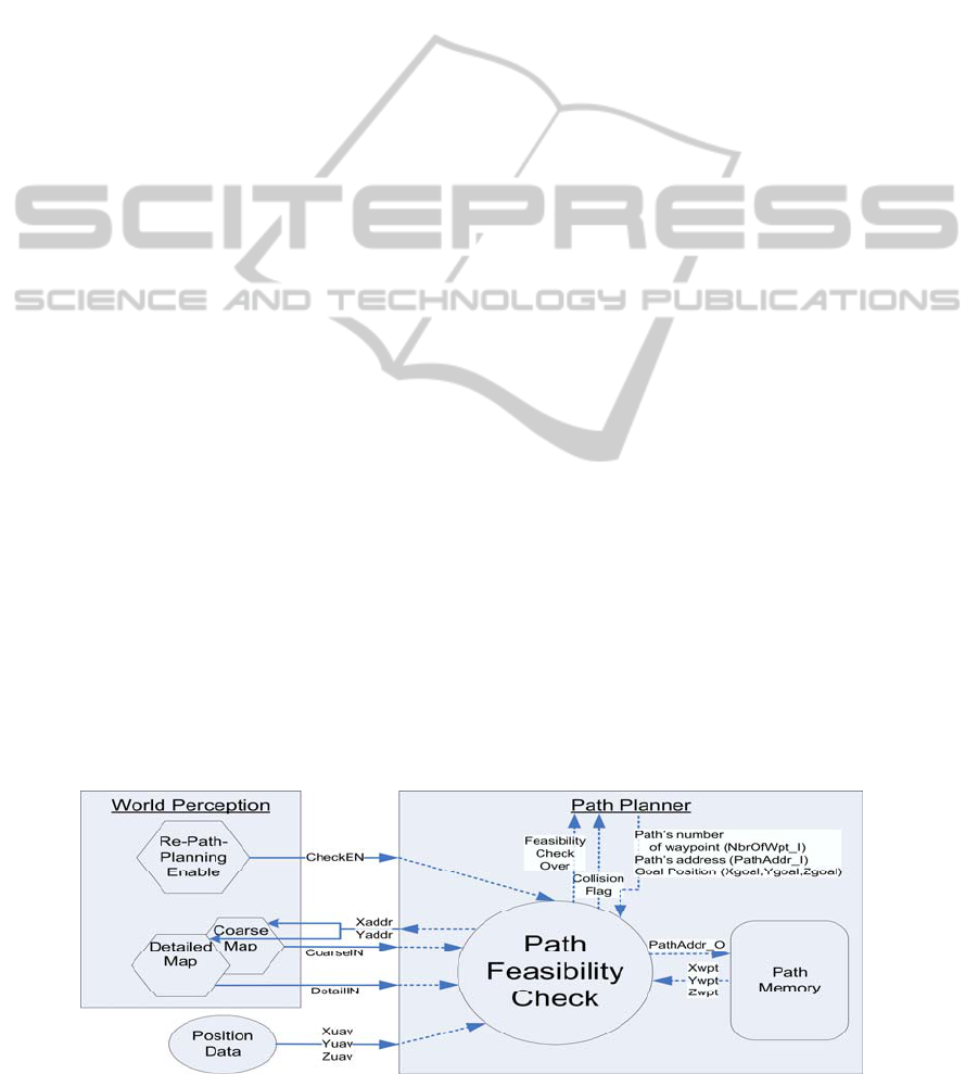
3.1 Structure Overview
Fig. 2 shows the structure of this project.
3.1.1 Inputs
Since this project focuses only on the feasibility
check, all inputs coming into the path planner (see
dotted arrows in Fig. 2) are connected directly to the
Path Feasibility Check module.
These inputs are:
Enable signal ChekEN, to start the feasibility
check;
Position Data (Xuav, Yuav and Zuav),
representing the current position of the UAV;
Path Planner data, which are: the number of
waypoints in the path, the path address, and the goal
position (Xgoal, Ygoal and Zgoal);
Xwpt, Ywpt and Zwpt are waypoint coordinates
read from a Path Memory implemented in Block
RAM, which stores all path waypoints, excluding
Figure 2: Structure of the hardware implementation.
TWO-TIERED RESOLUTION REAL-TIME PATH EVALUATION
323

the start (UAV position) and the end/goal waypoints;
The variable resolution maps, which consist of
two maps of the same area: a) the detailed map
captures the full resolution of the initial map (512 ×
512); and b) the coarse map (32 × 32) consists in the
maximum altitude values of the 16 × 16 squares
from the detailed map.
3.1.2 Outputs
A ‘collision flag’ is set as soon as a path altitude is
less than or equal to its related terrain altitude. If no
collision is found, a feasibility check runs to its
completion and an ‘over flag’ is set.
3.2 Functionality Overview
The feasibility check is being done into three phases
(see Fig. 3). A state machine with three states
controls how the feasibility-check cycles through it.
It will first wait for a path, and then it will evaluate
the first two path segments against the detailed map
and all other path segments against the coarse map.
The following subsection details these three phases.
Figure 3: Path Feasibility Check State Diagram.
3.2.1 Idle Phase
This state helps with synchronisation. It waits for the
enable signal to start the feasibility check process.
Once the enable signal goes high, it captures and
stores the input path waypoints and resets the
collision flag.
3.2.2 Detailed Evaluation
In this state, the first two path segments are
evaluated against the detailed map. As soon as one
collision is detected, the collision flag is set and the
system goes back to the IDLE state. If no collision
was detected in the first two segments and the path
has more than two segments, the process goes to the
Coarse Evaluation state.
3.2.3 Coarse Evaluation
This state is similar to the detailed evaluation state
except that the evaluation is done against the coarse
map. Once all segments are evaluated, the system
goes to IDLE.
The evaluation states are designed to cycle
through the following two steps as long as there is a
segment that has not been evaluated and as long
there is no collision detected. The first step consists
of the Bresenham line algorithm (Bresenham, 1965)
(Chiang, 1994), which is used to identify which cells
of the map need to be compared with the segment.
The current Bresenham module implementation
mimics the sequential Bresenham line algorithm. In
the second step, all identified terrain cell altitudes
are compared with their respective path segment
altitudes.
4 TESTING ENVIRONMENT
The testing trajectory selected is pictured in 3D in
Fig. 4 and in 2D in Fig. 5. A main characteristic of
this trajectory is that it goes close to a mountain,
forcing the feasibility checker to be precise. Another
characteristic is that the two first segments cover
about 2500 m from the UAV initial position which
could be a reasonable radius of detailed path
planning. Therefore, any additional segments are
treated in a coarse manner, adding negligible
computation time to the feasibility checker. Another
interesting aspect of the trajectory is that it is
considered as feasible overall from the perspective
of the detailed map, but the last segment is
considered as unfeasible from the perspective of the
coarse map shown in Fig. 6, forcing the path planner
to avoid risky trajectories.
Figure 4: 3D view of testing trajectory.
The feasibility check design was implemented in
VHDL, verified through simulation and synthesised
for a Virtex5-xc5vlx330 FPGA.
ICEC 2010 - International Conference on Evolutionary Computation
324

Figure 5: 2D view of testing trajectory.
Figure 6: Unfeasible third path segment in coarse map.
5 RESULTS AND FUTURE WORK
Since the aim of this work is to compute in real-time
the evaluation of the feasibility of path solutions for
an evolutionary algorithm UAV path planner, this
section presents the computation timing results and
the resources used from the FPGA. Moreover, this
section highlights related future works.
5.1 Timing Results
As mentioned in section 2.4.3, the feasibility check
of a path should be done in less than 5 μs for our
typical MALE UAV.
5.1.1 Feasibility Check Timing Breakdown
Table 2: Feasibility Check Timings.
Feasibility Check Step Time
(# of clock cycles
a
)
Capture of initial data 4
First Segment Evaluation
(55 points in testing trajectory)
55
Switch of segment 3
Second Segment Evaluation
(100 points in testing trajectory)
100
Switch of segment 3
Last Segment Evaluation
(6 points in testing trajectory)
6
Return to Idle/Wait State 3
TOTAL 171
a
One clock cycle equals 8 ns
Table 2 shows how many clock cycles are required
for each step of the feasibility check starting after
receiving the enable signal.
5.1.2 Clock Period
Based on synthesis reports, the longest delay in the
design (excluding the Bresenham algorithm
module), is about 8 ns so the maximum data rate is
125 MHz.
5.1.3 Feasibility Check Timing Scalability
Based on the above results, it is understood that the
specific Testing Trajectory is being feasibility
checked within less than 1.5 μs. This timing is well
under the 5 μs aimed for.
Even if there were any additional segments to the
path, the segments would be evaluated against the
coarse map as explained in section 3.2. Moreover,
the longest possible straight line on the map is the
diagonal that goes from one corner to the opposite
corner, and its length is 45 cells for the coarse map.
Hence the worst case scenario could add 14 x 45
cells to the feasibility check of the testing trajectory,
since a path cannot have more than 16 waypoints
(see section 2.2). However, it would mean that the
UAV is going back and forth from one corner to the
opposite one 14 times, which is an unrealistic
situation. Another reference is therefore required for
the worst case.
Within 3.5 μs (5 μs - 1.5 μs), 392 cells can be
evaluated; this distance represents more than 3 times
the perimeter size of the map which is reasonably
the longest path that could be expected to be
generated by the path planner. Therefore, one can
say that the two-tiered map resolution approach
presented by this work meets the sufficient-real-time
requirements, as set out in section 2 of this paper.
Moreover, during the first 1.5 μs our design can
evaluate 155 cells against the detailed map, hence
more than 500 cells can be evaluated within 5 μs
while covering a distance of more than 100 km. That
gives a cell evaluation rate of about 100 cells/μs.
5.2 Resources Used
Our design occupies only 0.1% of the FPGA logic
resources in terms of programmable look up tables
and 34% of the on-chip RAM. There is therefore
ample room for the implementation of the rest of the
path evaluation and the rest of the genetic algorithm
on the FPGA.
TWO-TIERED RESOLUTION REAL-TIME PATH EVALUATION
325

5.3 Future Works
The two-tiered map resolution, as implemented in
this work (using the equivalence of a sequential
Bresenham line algorithm), meets the sufficient-real-
time requirement for realistic path size, but doesn’t
meet the extreme-real-time requirement that requires
up to 5 times more speed (hence a maximum of 1 μs
for the feasibility check). Further studies would be
required to analyse what would be the best option
between duplicating a sequential Bresenham or
implementing a parallel Bresenham line algorithm
(similar to the one proposed by Wright (1990)).
One could extrapolate the idea of a two-tiered
search space for any other problem solved by an
evolutionary algorithm and see if such an
implementation could improve computation time for
the evaluation of the solutions.
6 CONCLUSIONS
This paper described a hardware design for the
implementation of the path feasibility check which is
a critical step in the path evaluation performed in
any path planning heuristic based algorithm. The
novelty of this design is that it uses two maps with
different levels of resolution to represent its world-
perception. This design, with its cell evaluation rate
of 100 cells/μs, proved to meet sufficient-real-time
requirements for all possible realistic paths. These
results validate the concept of using a two-tiered
resolution map in support of the feasibility check
phase required in any path evaluation.
REFERENCES
Atay, N., Bayazit, B., 2006. A motion planning processor
on reconfigurable hardware. Proceedings of IEEE
International Conference on Robotics and
Automation, pp. 125-132.
Braaksma, J. P., and Cook, W. J., 1980. Human
orientation in transportation terminals. Transportation
Engineering Journal. 106(TE2), pp. 189–203.
Voronoi, G., 1907. Nouvelles applications des paramètres
continus à la théorie des formes quadratiques. Journal
für die Reine und Angewandte Mathematik. 133: pp.
97-178.
Kavraki, L. E., Svestka, P., Latombe, J.-C., Overmars, M.
H., 1996. Probabilistic roadmaps for path planning in
high-dimensional configuration spaces. IEEE
Transactions on Robotics and Automation 12 (4): pp.
566–580.
Sridharan, K., Priya, T.K., 2005. The Design of a
Hardware Accelerator for Real-Time Complete
Visibility Graph Construction and Efficient FPGA
Implementation. IEEE Transactions on Industrial
Electronics. Vol.52, no.4, pp. 1185-1187.
Priya, T. K., Sridharan, K., 1999. An efficient algorithm to
construct reduced visibility graph and its FPGA
implementation. Proceedings of the 17th International
Conference on VLSI Design. pp. 1057-1062.
Vachhani, L., Sridharan, K., 2008. Hardware-Efficient
Prediction-Correction-Based Generalized-Voronoi-
Diagram Construction and FPGA Implementation.
IEEE Transactions on Industrial Electronics. Vol.55,
no.4, pp. 1558-1569.
Sudha, N., 2007. A Hardware Accelerator for Path
Planning on a Distance Transform. IEEE International
Conference on Control Applications. pp. 409-414.
Cocaud, C., 2006. Autonomous Tasks Allocation and Path
Generation of UAV’s. Dept. of Mech. Eng., Univ. of
Ottawa, Ontario, Canada.
Samet, H., 1980. Region Representation: Quadtrees from
Boundary Codes. CACM (23), No. 3, pp. 163-170.
Judd, K. B., 2001. Trajectory Planning Strategies for
Unmanned Air Vehicles. Dept. of Mech. Eng.,
Brigham Young Univ., Provo, USA.
Chanthery, E., 2002. Planification de Mission pour un
Véhicule Aérien Autonome. École Nationale
Supérieur de l’Aéronautique et de l’Espace, Toulouse,
France.
Allaire, J. C. F., Tarbouchi, M., Labonté, G., Fusina, G.,
2009. FPGA Implementation of Genetic Algorithm for
UAV Real-Time Path Planning. Journal of Intelligent
and Robotic Systems. Vol 54, pp. 495-510.
Bélanger, D., 2008. Trajectory Planning with Ant Colony
Optimization. Dept of Math and Comp Sc, Royal
Military College of Canada.
Eslam Pour, N., 2009. Particle Swarm Optimization
applied to UAV Path Planning. Dept of Math and
Comp Sc, Royal Military College of Canada.
Bresenham, J.E, 1965. Algorithm for Computer Control of
a Digital Plotter, IBM Systems Journal. Vol 4,
no 1,
pp. 25-30.
Chiang, L. E., 1994. 3-D CNC Trajectory Interpolation
Using Bresenham's Algorithm. Proceeding of IEEE
International Symposium on Industrial Electronics.
pp. 264-268.
Wright, W. E., 1990. Parallelization of Bresenham’s Line
and Circle Algorithms. IEEE CG&A. Vol 10, no 5, pp.
60-67.
ICEC 2010 - International Conference on Evolutionary Computation
326
