
Development of Architecture and Caching System for
Improving the Performance of Fuel Management System
Mahmoud Ali Ahmed and Mustafa Ali Taha
Department of Computer Science, Faculty of Mathematical Sciences
University of Khartoum, Khartoum, Sudan
Abstract. Fuel Management System (FMS) is about managing and accounting
for fuel. While implementing FMS in Sudan, some problems are noted, like
system delay, inaccuracy and unavailability of the system. These problems and
others make fueling companies and customers unsatisfied with the FMS.
This paper aims to solve the noted problems by introducing enhanced system
architecture and integrating a Caching System in the FMS architecture to
enhance the performance, reduce system delay and increase the availability of
the system.
After architecture was developed, simulation programs were implemented to
simulate the interactions required to re-fuel and to provide statistics results that
help in evaluating the proposed FMS. The results of simulation programs were
presented as the average service time, number of customers in system, number
of customers in queue, idle probability and other results. The average service
time was reduced and all results obtained emphasize the effectiveness of the
proposed solution.
1 Introduction
FMS consists of equipments and software designed to automate the process of
purchase and sale of any fuel product inside fueling site. Fuel is delivered by the
supplier to the tank at fuel distribution site and then to the customers; when
distributing fuel, some features are required such as accuracy, integrity, and caution of
every person that uses the facility to ensure that the losses is only due to natural
causes such as evaporation. Losses are becoming a great concern for Management and
Accounting departments especially in the public sector [1].
By using FMS many benefits can be gained such as it becomes easy to account for
every liter of fuel purchased and to know where the fuel goes, hence the organization
will avoid fuel theft and misuse [1], also re-fueling becomes easier and faster and
ensuring the proper fuel was delivered for specific vehicle becomes available with the
ability of restricting access to re-fueling until the maintenance is performed [1].
FMS principle is the connection and control of all dispensers to an interface unit
which is connected to the controller computer to control these dispensers by the
software installed on the computer, to enable all fueling operations to be reported,
Ahmed M. and Ali Taha M..
Development of Architecture and Caching System for Improving the Performance of Fuel Management System.
DOI: 10.5220/0003111700030014
In Proceedings of the International Workshop on Semantic Sensor Web (SSW-2010), pages 3-14
ISBN: 978-989-8425-33-1
Copyright
c
2010 SCITEPRESS (Science and Technology Publications, Lda.)

controlled, recorded and customers can easily monitor their vehicle’s fueling
operation [2].
FMS must have the ability to identify users (by using identification method like:
Attend key, Smart cards, Automated Teller Machine (ATM) cards etc...) in order to
enable the system give authorization to the dispenser for fueling. Fueling information
are recorded at the end of the fueling [2]; then it’s transferred automatically to the
central server through an appropriate network connection [3].
As FMS consists of many components (hardware and software) and the system
might be integrated with other systems such as Banking System and/or other sites
through complicated network, the system will be affected with most of networks
problems, so there is a need for techniques to reduce the effect of network problems
to the system. Also the architecture of the automation system and the equipments used
for connecting the dispensers to the system are important to be considered because
any loss or delay of re-fueling data is not acceptable [2]. Therefore, it is vital to stick
to international standards during the design and implementation of these systems [2],
so it is powerful to construct simulation programs to test new systems before
implementing them.
2 FMS Infrastructure
2.1 Fuel Management Sub-Systems
FMS is a complex system, so a good way to deal with the system is to divide it -
according to functionalities - into small subsystems.
The main sub-system in FMS is Pump Controlling System; it connects all fuel
dispensers to the station controller computer resulting in the controlling of these
dispensers by the software installed on the computer [2]. The system operates the fuel
dispenser only to valid customers and vehicles [4].
An optional system is a Head-Office System. It delivers the capability of
programming identification devices. Head-office system sends all the fleet
information to the automation solutions in all stations. The system stores data in the
central database, since all the transactions in the stations are transferred to the head-
office. Information stored in the head-office is later used to generate reports and
submitted to the users [2].
2.2 Fuel Management Identification Equipment
FMS consists of a fuel island controller, software, some types of identification
devices (as shown in Table 1) and the Central Controller that normally communicates
with other sites to exchange the data [1].
4

Table 1. Identification equipment.
Identification
equipment
Description
Smart Chip Key
Contains a microchip that can be programmed and
reprogrammed.
Smart cards
Standard size card with an embedded read/write memory
chip and it works exactly like smart Chip Key.
Credit cards
It allows 24 hour, unattended, self-serve operations for
credit card holders [5].
Vehicle Identification
System
It is a coil ring integrated with electronic chip that
installed at the opening of the fuel tank to enable
collecting data from the vehicle [6].
2.3 Fuel Management System Sensors
A sensor can be defined as "a device that detects (senses) changes in the ambient
conditions or in the state of another device or a system, and conveys or records this
information in a certain manner" [7]. FMS and its subsystems contain many sensors to
monitor system status (i.e. volume, motion, temperature and other sensors) where all
sensors are connected with FMS network through defined protocols. FMS Sensors are
located in station forecourt (to detect vehicle motion), in fuel dispenser (to measure
delivered fuel volume), in station fuel tanks (to measure temperature, viscosity and
other physical parameters) and in the vehicle .All sensors are responsible for the
accuracy and performance of the system.
2.4 Off-line Automation and On-line Automation
Vehicle identification and station automation operate in two different modes [2]:
Off-line automation: All the vehicle information, Black/White List is stored in the
automation systems located at the station. The vehicle approaching the station is
controlled by this automation system and then re-fueled. Daily sales are transferred to
the oil company head-office on a batch transfer. During the batch transfers, the fleet
list definitions are updated [2].
On-line automation: All the vehicle information, Black/White List is stored in the
servers of company head-office or in the servers of the Internet Service Provider (ISP)
that is responsible for central communication and data storage. The vehicle that
approaches the station is detected by the station controller and queried on the head-
office system. Fueling, regional and time limitations of the vehicle are checked from
the head-office [2].
2.5 Payment Methods
Payment methods are an important issue that can be considered when designing FMS.
In general, there are two types of payments, post-paid and pre-paid [2].
5

In the post-paid method the customers will take fuel and can also be provided with
some services and/or products and will pay the money later, so the off-line
automation is suitable for this case.
In the pre-paid method the customers will take fuel and can also be provided with
some services and/or products only if they have sufficient amount defined in the
system, so the on-line automation is suitable for this case.
3 Related Works
This section discusses some FMSs according to the author experience, and then an
ATM network model is highlighted to help in designing the enhanced FMS.
PumpOmat is a forecourt automation system developed by Turpak – Turkish
company- for dispenser automation .When installing and running PumpOmat in
Sudan, the author found that there were some problems in the system. The first
problem is that when the customer presents his identification, the system takes long
time (approximately 40 Sec.) to start the dispenser and the dispenser can not stop at
the target volume or amount exactly. Also the system supports only post-paid
customers.
Another FMS is EasyFuel Plus which is developed by OTI. Also this system has
many problems; the first problem is that when the customer presents his
identification, the system takes long time (approximately 36 Sec.) to start the
dispenser. Another problem is, although the system supports pre-paid customers but
the tag that holds the data must be returned to the fuel company for balance reloading,
so from the author point of view it is not practical.
The author observes that the FMS is similar to the ATM Network in which the
ATMs are owned by different banks, and the customer may use any ATM even it
doesn’t belong to his bank. All ATMs are connected using a main switch which
connects them to the core systems [8]; this scenario has been applied to proposed
FMS for network considerations.
4 Methodology
4.1 Caching System
Caching is a technique aimed at bringing parts of an overall data set closer to its
processing site [9], and can be used in FMS to retrieve customer data from 'outside'
servers to the station computer to enhance the performance.
Caching can improve network performance in two ways. First, when serving
clients locally (customer data), caches hide wide-area network latencies. Second,
temporary unavailability of the network can be hidden from customers, thus making
the network appear to be more reliable [10].
Caching systems eliminate the need to contact the originating server. Thus,
additional network communication can be avoided, so caching systems can save
6

bandwidth, enhance server load balancing, perceived network latency reduction, and
increase content availability [10].
The main drawback of caching system is data inconsistency, and this drawback
does not affect the FMS because the data is retrieved when the customer is in the
station and the update occurs after the customer leaves the station.
4.2 Simulation and Modeling
Simulation is used as a tool to better understand and optimize the performance and
reliability of systems [11]. Modeling and simulation is a valuable tool in the analysis
of large-scale networks and computer systems [12].
Simulation and modeling technique will be used after the development of
architecture and Caching System for FMS to ensure the correctness of the design.
4.3 Queuing Analytical Models
Queuing theory is usually used to define a set of analytical techniques in the form of
mathematical formulas to describe properties of the processes with a random demand
and supply (waiting lines or queues). Queuing formulas are usually applied to a
limited number of pre-determined simplified models of the real processes for which
analytical formulas can be developed [13].
There are three main concepts in queuing theory which are customers, queues, and
servers (service mechanisms). In queuing systems, customers are generated by an
input source according to a statistical distribution that describes their interarrival
times (the times between arrivals of customers). The customers join a queue and
waiting for some event to occur (i.e. take a fuel). At various times, customers are
selected for service by the server (service mechanism). The basis on which the
customers are selected is called the queue discipline which can First-come-first-
served (FCFS) or Last-come-first-served (LCFS) or Random selection or Priority
selection [14] .In some models customers can decide not to join a queue if the queue
length is too long. This phenomenon is called Balking [14].
5 FMS Architecture
This section proposes FMS architecture with discussion of two system scenarios and
suggests a solution for them.
One solution to reduce the waiting time, increase the availability and enhance the
integrity at the fuel station is the 'Caching System' that is to start retrieving the fueling
data while the vehicle/customer in the waiting queues.
When the customer needs re-fueling at fuel station, two situations may occur. The
first situation is that the customer does not find any vehicle in re-fueling process, so
there is no queue and he/she can stop at the fuel dispenser directly. The second
situation is that the customer finds there is a vehicle in re-fueling and/or other
7

vehicles are waiting in the queue for re-fuel, in this case the customer will join a
queue.
In the first situation the customer can use his/her identifier to re-fueling, and the
customer will wait for a few times while the system is retrieving the data.
In the second situation, there is a possibility that the fueling information for the
customer is stored in some server outside the station, a good technique is to retrieve
the fueling information while the customer is waiting in the queue.
When a customer comes to station and joins a queue, he/she will be waiting in the
queue until he/she becomes the first customer in the queue, and then a capturing
device will capture the vehicle plate number and transfer it through the controller to
the station computer. The station computer will establish a communication with other
severs to get the fueling information for this vehicle and store them temporally in the
station computer. When the customer leaves the waiting queue and stops at the
dispenser and uses his/her identifier, the request will be forwarded by the Central
Controller to the station computer and the data will be found in the station computer
because it is prepared while the customer was waiting, so by implementing this
solution the waiting time will be reduced.
5.1 Components
FMS must contain Station Computer (SC) at each station to provide and process data
for station devices.
Since the one fuel company can have more than one fuel station, there is a need
for a centralized server (Fuel Company Server (FCS)) to collect and analyze data
from different stations.
Since there is more than one Fuel Company and the customers need the ability to
take their quantities from any station, there is a need for a common centralized server
(Main Server (MS)) to enable data exchange between different FCSs and SCs. Since
all traffic must pass through the MS it can act as a point of solving conflicts and
coordinating between fueling companies.
In some cases if the customer uses his/her banking card, there is a need for
Banking System (BS).
Also customers can use their computers (Customers Computer (CC)) to manage
and monitor their fleet remotely.
5.2 System Architecture
This section proposes an enhanced system architecture that helps in reducing the
waiting time, increasing the availability and enhancing the integrity of the system.
The architecture as shown in Fig. 1 consists of the Main Server, Banking System,
Fuel Company Server, Station Computer and customer Computer.
In this architecture The MS, FCSs and SCs connect through one network, but each
transaction must pass through the MS. Also, the MS is connected with the BS to
provide services to the customers who have banking account.
In general, when the customer needs to re-fuel or needs a service from fuel station,
there are two ways for paying, using FMS identifiers or using banking cards.
8
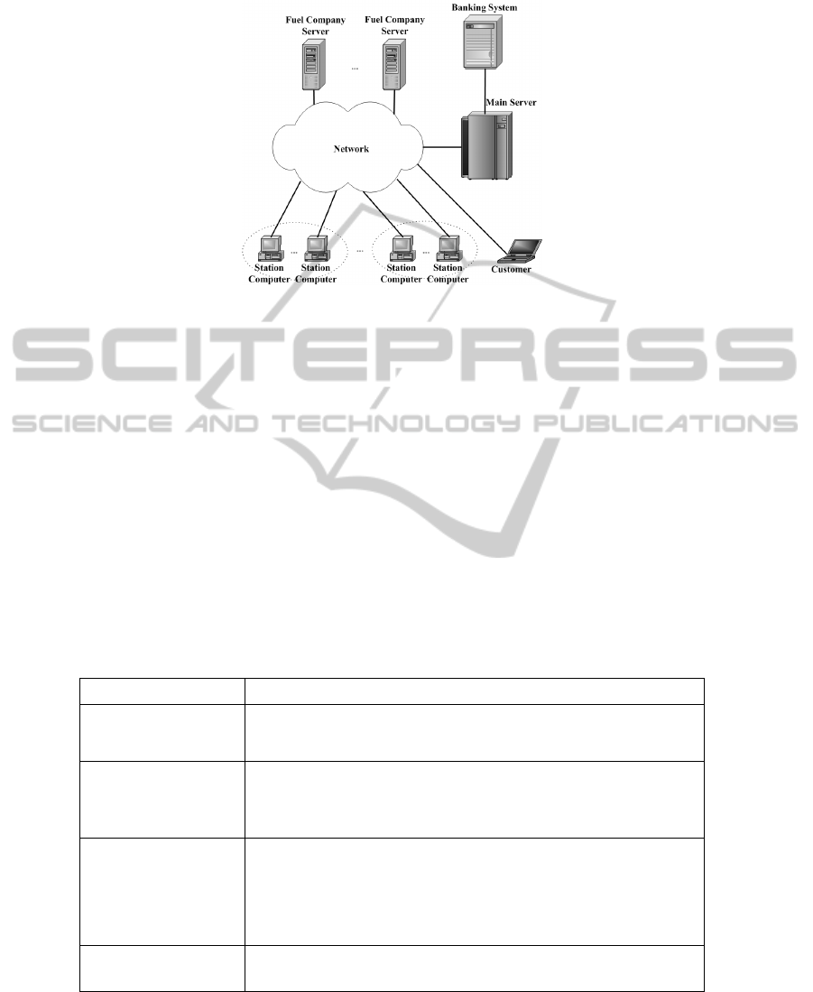
Fig. 1. The proposed architecture.
The first case, If the customer uses one of FMS identifiers, the SC will request the
MS to retrieve the fueling information from the place where it is stored; the MS
searches in its database to determinate the appropriate FCS and then requesting it to
get the fueling information, the FCS will response to the MS and the response will be
forwarded from the MS to the FCS and then to the SC.
The second case, if the customer uses his/her banking card, the SC will request the
MS to dept the amount of money needed from the BS; the MS requests the BS to dept
the customer account, the BS will search for customer account and the result is sent to
the MS; the MS will forward the result to the SC.
In all cases, after re-fueling the dispensed fuel amount and cost will be processed
and transferred to the FCS and/or other Server(s) and it depends on if the customer
belongs to the fuel company or others.
While availability is an important issue when designing FMS, Table 2 shows the
effect of component and/or link failure to the system.
Table 2. The effect of component or link failure to the system.
Component / Link Effect of component or Link failure to the system
SC / Link between
SC and network
The station is out of service, so customers of this fuel company
and customers of other fuel companies can not use this station.
FCS / Link between
FCS and network
Customers of the fuel company can not fuel at fuel company or
each other station (also if it’s owned by different companies).
But company customers can use their banking card.
MS / Link between
MS and network
Customers of any fuel company can use company fuel stations
only (required to modify the SC logic and became that: if it
detects the failure of the MS, it can connect directly to its FCS).
Since the BS is connected to the MS, the customers are unable
to use their banking cards.
BS / Link between
BS and MS
Customers of any fuel company can not use their banking
cards.
9
As shown above this architecture retrieves the data from the FCS in 6 steps only,
so it reduces the time to retrieve the data and enhances the availability of data as
shown in the case of component or link failure, thus it is a powerful architecture to
implement.
Start
Customer arrive to station
Cash customer YesNo
Found free dispenser ?
Presents identifier ,pre-
paid card or banking card
Join a queue until becoming first
(in queue)
Yes
No
Request the customer to enter the needed
amount
Is the customer allowed to re-fuel ?
Yes
No
Is the amount of fuel
entered allowed ?
System presets the amount in the dispenser and start fueling
and display maintenance information
Display message: No sufficient credit
Yes
After fueling, stop the dispenser and update the
required servers
Customer leave the station
End
Display message: Not allowed
Send
request
to the
Main
Server
Payment type
Send
request
to the
Main
Server
Send request to the Main Server
process
and send
data to
station
Retrieve data from the Fuel Server
and send it to station
Retrieve
data from
the
Banking
system
and send it
to station
Pre - paid
card
FMS
Identifier
Customer data available at Station Computer
The Plate No. Reader captures
and sends plate number to the
Main Server
The Main
Server searches
and sends the
result to the
Station
Computer
Data available in Station
Computer
Yes
Found free dispenser ?
Join a
queue
Re-fuel using the pump attendant key
and pay in cash
Yes
No
No
No
Banking
card
Try other
payment type ?
Yes
No
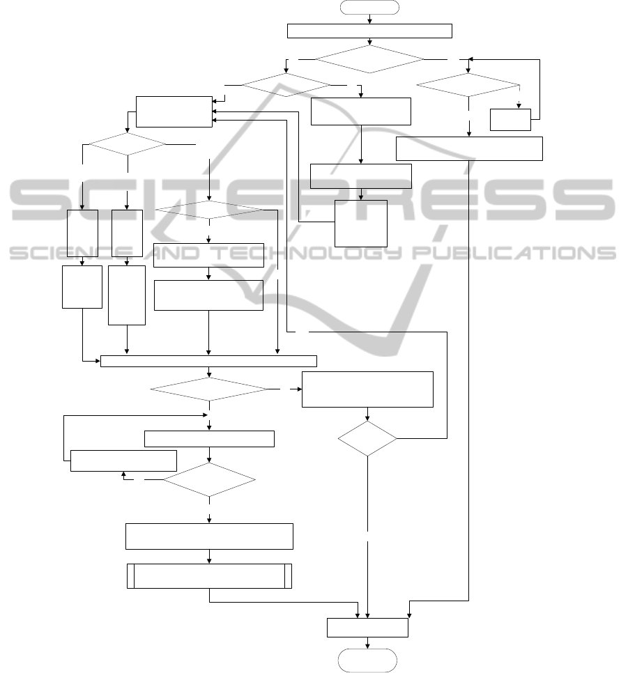
Fig. 2. FMS Framework.
10
5.3 System Framework
By integrating the station system with other servers, it produces a Comprehensive
FMS that provides several services to customers with 'acceptable' performance. Fig. 2
shows an FMS framework that summarizes the steps required to re-fuel.
6 Results and Discussion
This section is divided into three sub-sections that show and discuss three
implemented FMS simulation programs. The first program is for simulating the
behavior and steps required to re-fuel. The second program is for calculating the
average service time while the third program is about calculating average waiting
time, calculating the number of customers in the system and the number of customers
in the waiting queues and other results.
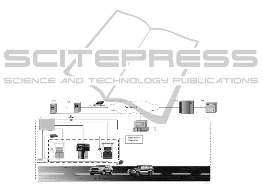
6.1 FMS Behavior Simulation
A simulation program that illustrates all cases and steps for re-fueling using the
proposed architecture is implemented. Fig. 3 shows a screen shot from the simulation
program.
Fig. 3. Screen shot of FMS behavior simulation.
6.2 FMS Average Service Time Calculator
Average service time is a basic parameter that is required in any simulation program.
Since FMS has different customers type (customers with different authentication
methods), and the way to retrieve the data is different from method to other, it is
required to calculate the retrieving time.
Customers come to station to re-fuel in different quantities, and that will affect the
dispensing time (time required to re-fuel the desired quantity).
11
Since the retrieving time and dispensing time mostly compose the service time, then
the average service time for FMS customers is the summation of data retrieving time
and fueling (dispensing) time divided by the number of customers.
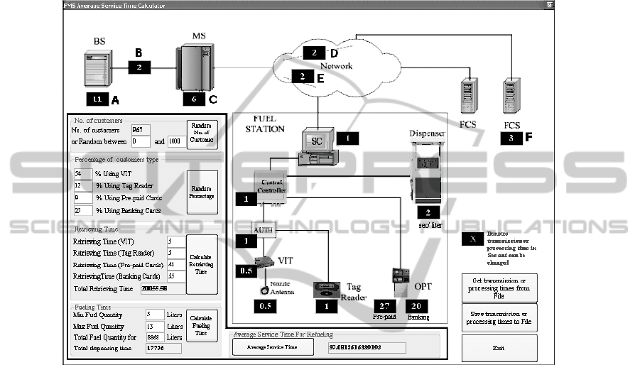
As shown in Fig. 4, a simulation program that calculates the average service time
was implemented (values used for transmitting and processing times are approximate
times and can be changed and it determined by author experiments and experience).
Fig. 4. Average Service Time Calculator.
As shown in Fig. 4 above, when using the proposed architecture the Average
Service Time is 39.081.
When integrating Caching System with the proposed architecture (the time
parameters A, B, C, D, E, F, set to zero because the data is available at the Station
Computer) , the Average Service Time will be 30.431Sec.
6.3 FMS Statistics Calculator
A simulation program (M/M/1 Solver & Simulator that is available at :
http://staff.um.edu.mt/jskl1/simweb/simmm1.html ) which is developed by Jaroslav
Sklenar was used to get the number of customers in system (Ls), number of
customers in queue (Lq), Time in system (Ws), Time in queue (Wq), Idle probability
(p0), Server utilization (r) and other results.
When using ‘FMS Average Service Time Calculator’ program, the calculated
average service time is (approximately 0.5 Min.). And each customer arrives after
12
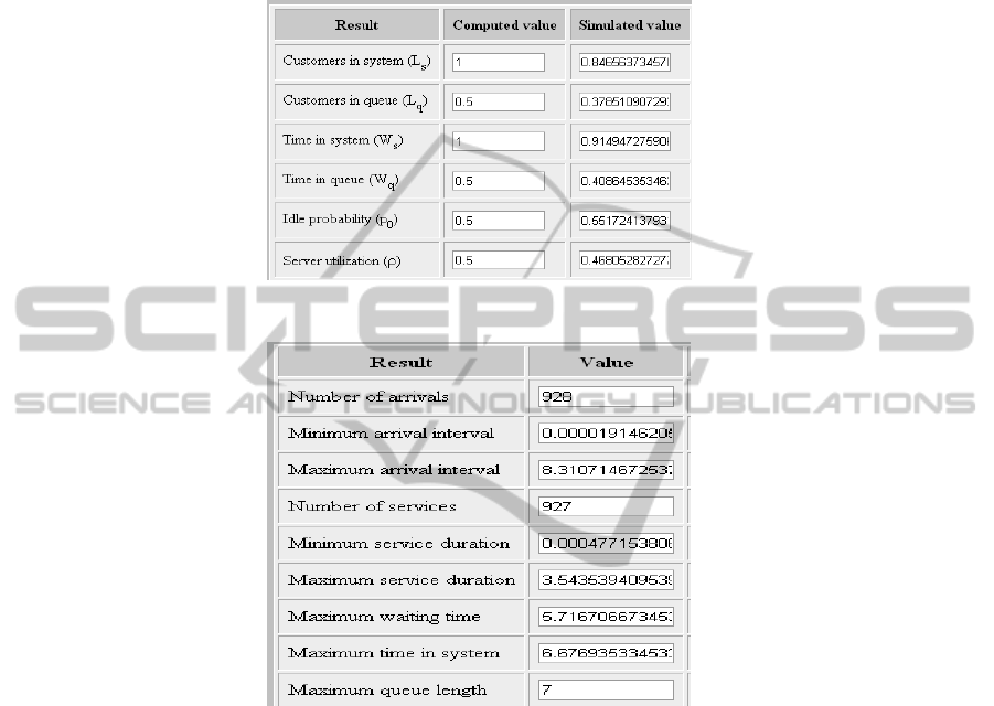
(1.0 Min.) from the previous one, the arrival rate will be (1 customer/minute) and the
service rate will be (2 customers/minute). The author assumes that if there is 10
customers in waiting queue the customer will not join the system (buffer size is 10
customers). Fig. 5 and Fig. 6 below show the simulation results.
Fig. 5. Basic simulation results.
Fig. 6. Additional simulation results.
When simulating other systems, a simulation program shows that systems are
unstable because the arrival rate is greater than the service rate. In the proposed
system the architecture helps to improve the service rate by introducing common fuel
servers. Also as shown in Fig. 5 and Fig. 6, the Caching System reduces the average
service time that improves the system.
7 Conclusions
A powerful architecture that connects all fuel stations (for all fueling companies) in
the same network to enable customers to re-fuel at each fuel station regardless of the
station owner is designed to provide a set of services with ‘acceptable’ performance
13

and to reduce system delay and increase the accuracy of fuel volumes taken by
customers. Also the proposed architecture enables customers to re-fuel using various
payments methods.
According to the importance of evaluating the performance of the proposed FMS,
various simulation programs developed to illustrate the interaction scenarios between
different components, and to measure some system statistics such as average service
time, average waiting time and other statistics that considered important for fueling
companies and customers. The results obtained from the simulation programs
reflected the efficiency of the proposed FMS.
References
1. Municipal, Internet: http://www.municipalfuelmanagement.com , [Nov. 3, 2009].
2. TURPAK ELECTROMAGNETIC, Internet: http://www.turpak.com.tr, 2006 [Oct. 11,
2009].
3. Taurus systems Inc, Internet : http://www.Taurus-systems.com , [Sep. 25,2009].
4. Coencorp Inc., Internet: http://www.coencorp.com/e/provsrvover.htm, [Sep. 26, 2009].
5. PFA International Ltd., Internet : http://www.pfainternational.com/products.htm , 2006
[Oct 1,2009].
6. E - Drive Technology Ltd., Internet: http://www.e-drivetech.com, 2004 [Nov. 10, 2009].
7. WebFinance Inc.,"Sensor." Internet: http://www.businessdictionary.com/definition/
sensor.html, 2010 [Jul. 26.2010] .
8. CSFI.,Internet http://www.csfi.com/ezswitch.cfm , 2009 [Jun 13.2010] .
9. M. Baentsch, L. Baum, G. Molter, S. Rothkugel, P. Sturm, "World-Wide Web Caching The
Application level view of the Internet", Internet: http://www.syssoft.uni-trier.de/
systemsoftware/Download/Publications/communic.pdf , 1997 [Jul. 25.2010].
10. Greg Barish, Katia Obraczka , "World Wide Web Caching: Trends and Techniques",
Internet: http://inrg.cse.ucsc.edu/katia-pubs/cache-survey.pdf , Sep. 2009 [Jul. 25,2010] .
11. L. F. Perrone , Y. Yuan , and D. M. Nicol , “Modeling and Simulation Best Practices for
Wireless Ad Hoc Networks” , Proceedings of the 2003 Winter Simulation
Conference,2003, pp. 685 – 693.
12. G. R. Yaun, “Efficient Large-Scale Computer and Network Models using Optimistic
Parallel Simulation “ Ph.D. thesis , Rensselaer Polytechnic Institute , New York, Jun. 2005.
13. A. Kolker , “Queuing Analytic Theory and Discrete Events Simulation for Healthcare:
Right Application for the Right Problem” , Internet :http://www.iienet2.org/uploadedFiles/
SHS_Community/Resources/QueuingAnalyticTheoryandDiscreteEventsSimulation.pdf ,
[Nov. 15,2009].
14. A. Ferrier,“What is Queuing Theory?” , Internet : http:// www.andrewferrier.com/oldpages/
queueing_theory/Andy/what_is_queueing_theory.html, Jun. 1999 [Nov. 15,2009] .
14
