
A MODEL BASED SYSTEMS ENGINEERING PROCESSES
DEPLOYMENT FRAMEWORK
Clémentine Cornu, Bernard Chiavassa
Eurocopter, ETZP, Aéroport International Marseille Provence, 13725, Marignane Cedex, France
Vincent Chapurlat
LGI2P - Site EERIE de l'EMA, Parc Scientifique George Besse, 30035, Nîmes Cedex 1, France
François Irigoin
Mines ParisTech – CRI, 35 Rue Saint Honoré, 77305, Fontainebleau Cedex, France
Keywords: Model based systems engineering, Systems engineering process, Graphical modeling framework,
Interoperability.
Abstract: Systems Engineering is a tried and tested methodological approach to design and test new products. It acts
as a model based engineering approach and promotes for this purpose a set of standardized collaborative
processes, modelling languages and frameworks. The systems engineering processes imply many
interactions and exchanges between resources. Nevertheless, currently there is no method guiding
companies in the deployment of these processes adapted to meet their stakeholders' expectations.
Particularly, interoperability abilities and capacities which are required at each level of the company and by
each resource remain poorly addressed. The purpose of this paper is twofold: 1) to present an approach for
deploying systems engineering processes taking into account the interoperability assessment of resources to
guide their allocations; and 2) to identify and propose a dedicated software framework having to be
developed in order to support this approach.
1 INTRODUCTION
The Systems Engineering (SE) approach is
considered today as an efficient methodological and
interdisciplinary approach. It promotes a set of
processes required to design and test a new product
or service (ISO/IEC, 2008) (INCOSE, 2010) since
the organization and the behaviour of a company are
often described under the form of a map of inter
dependant processes. Let us remain that a process
can be defined as “a logical sequence of tasks
performed to achieve a particular objective. A
process defines “WHAT" is to be done, without
specifying “HOW” each task is performed"
(Estefan, 2008).
Nevertheless, despite the fact that SE is a tried
and tested methodology, it is still difficult for
companies to apply it. First, there is no method
available describing how to practically deploy SE
within companies. Second, the resources (e.g. actors,
teams, computers, machines, software, etc.) having
to be used, involved and coordinated all along a SE
process generally do not have the required abilities,
capacities, and even facilities, to efficiently work
together, share information and communicate during
the SE process activities. This can be considered as
an interoperability question which is not currently
considered during the deployment. Let us remain
that interoperability can be defined as the "ability of
enterprises and entities within those enterprises to
communicate and interact effectively"(ISO, 2010). It
is then considered here as a key factor of SE
processes deployment.
The purpose of our research work is to provide
companies a method to help them preparing the
deployment of SE processes tailored to meet all
stakeholders’ expectations, interoperability
requirements and specific constraints linked to the
65
Cornu C., Chiavassa B., Chapurlat V. and Irigoin F..
A MODEL BASED SYSTEMS ENGINEERING PROCESSES DEPLOYMENT FRAMEWORK .
DOI: 10.5220/0003611700650070
In Proceedings of the 6th International Conference on Software and Database Technologies (ICSOFT-2011), pages 65-70
ISBN: 978-989-8425-76-8
Copyright
c
2011 SCITEPRESS (Science and Technology Publications, Lda.)

nature and the strategic objectives of the company.
This method promotes:
A roadmap of all activities the company must
perform to define and formalize the adequate
processes to deploy,
A set of reference models and examples
clarifying for instance the definition of
activities or the allocation of resources, guiding
thus the deployment and the tailoring of the
proposed processes to the company,
A meta-model describing all concepts required
during the modelling of the components and the
way of working of the company,
A specific assessment method to appraise the
interoperability of resources and thus to help in
their allocation.
This paper focuses on the practical implementation
of the SE process to deploy. This implementation is
based on a framework which is defined here as a
consistent group of software tools supporting the
four elements of the methodological approach
presented above.
This article is structured as follows: after a
short presentation of the proposed deployment
approach performed in Section 2, Section 3 presents
the specific needs for software framework induced
by this approach and presents the retained solutions
before concluding.
2 OVERVIEW OF DEPLOYMENT
ACTIVITIES
The purpose of this section is to outline the main
principles and steps of the proposed deployment
approach for SE processes. After defining the team
in charge of the deployment, the four main steps of
the approach are: 1) Model ideal processes to deploy
and their relationships, 2) Model existing processes
and their relationships, 3) Specify the processes to
deploy and 4) Define practical implementation.
2.1 Model Ideal Processes to Deploy
and their Relationships
The goal is to provide a model describing the
idealised company’s vision of a (set of) SE
process(es) highlighting what would be each SE
process, what must be the appropriate organization
to adopt and what resources are required for optimal
functioning of the process(es) to deploy. At this
stage, "ideal" means there is no point here of being
influenced by the current break-down structure of
the company or by the current allocation of tasks.
This stage requires firstly to select a reference
document (e.g. (ISO/IEC, 2008)) providing all
theoretical definitions of processes. Secondly, the
deployment team models these ideal processes
taking into consideration the global specificities of
the company and business area. To this end, a set of
modelling languages has to be selected and adopted
following the principles of enterprise modelling
(Vernadat, 1996). Thirdly, the team models for each
SE process, the process in charge of managing it.
Finally, a deployment process is defined for each
{SE process; management process} couple.
2.2 Model the Existing Processes and
their Relationships
The purpose is now to characterize and analyse the
current company’s organisation defined for the
design of new products or services. During this
analysis, no constraint is induced by the ideal model
of SE processes to deploy. The existing activities
and resources involved or that could be involved in
the design of products or services are characterized
and modelled as an AS-IS model. To perform this
stage, the team must select the scope of the analysis
("Which project/program will be used as a basis?"),
collect information, and then formalize this
information by using the same formalism as the one
used in stage 2.1.
2.3 Specify the Processes to Deploy
A TO-BE model (Chapurlat & Braesch, 2008) is
then proposed mixing and merging when necessary
the ideal process(es) models and the AS-IS model.
The goal is to perceive significant gaps and thus
highlights ways of improving the current
organization. The TO-BE model is thus built to
share the trade-offs found between the current and
the ideal organizations. Figure 1 summarizes the
detailed activities to be carried out during this step
for each SE process to deploy but also for the
relevant management processes having to be
deployed at same time.
Among the activities described in this figure let
us focus on the resources allocation which is done
according to potential and effective interoperability
assessments. Interoperability refers here to the
capacities and abilities of one or two resources to
collaborate efficiently from organisational,
conceptual and technical points of view.
According to the needs of the deployment team,
the appraisal is performed either on one single
resource to assess its own abilities to
interoperability; or on a couple of resources to
especially assess their compatibility.
ICSOFT 2011 - 6th International Conference on Software and Data Technologies
66
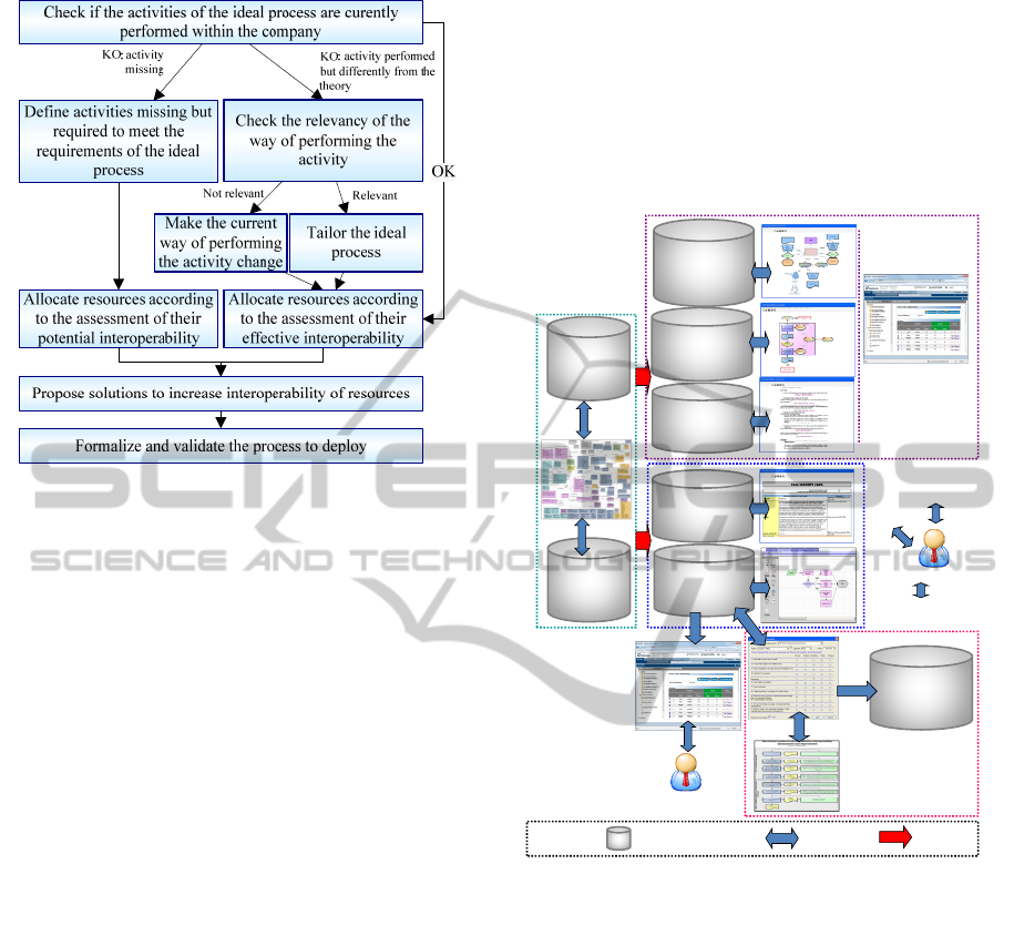
Figure 1: Final definition of processes to deploy.
Therefore, this appraisal is done either to define a
current status of the ability of the resource(s) to be
interoperable (effective interoperability); or to
anticipate the future behaviour of resource(s) during
new collaborations induced by the new organization
provided by SE processes (potential
interoperability). In this last case, the
interoperability appraisal can be used by the
deployment team for example to decide between two
equivalent resources, or to detect interesting
improvements on existing resource before any
physical deployment.
2.4 Define Practical Implementation
Finally, the deployment team defines an action plan
for the deployment addressing topics such as:
the planning of the deployment,
the organization of the communication about
the deployment,
the definition of the required training activities
and the design of training materials,
the definition of the transition phase: the
mapping between old and new organization,
roles and responsibility, way of working, tools,
etc.
In order to support all activities for the preparation
of the deployment, some software tools are required.
Their specifications are provided in next section.
3 FRAMEWORK
SPECIFICATION
Figure 2 provides an overview of the tools
constituting the framework having to support the
preparation of the deployment of SE processes. All
theses tools are described in the following sections.
Process
models
Interoperability
tool (§ 3.4)
Interoperability
assessment
reports
Workflow
engine for the
management
of the SE
processes
deployed
Meta-
model
Workflow engine
for modelling
activities
Meta-model’s
elements full
description
Meta-Model
extracts formatted
with the defined
graphical definition
Modelling good
practices and
advices
Modellers
Descriptions
of the meta-
model’s
elements
Final SE process users
Tools supporting
the modelling
(§3.3)
Modelling
tool (§3.2)
Interoperability
assessment
method
Conceptual
framework
(§ 3.1)
Database + DBMS Interaction
Constraints
Caption
Graphical
definition of
concepts
Generic
models
Figure 2: Overview of tools needed in the preparation of
SE processes deployment.
3.1 Conceptual Framework
The deployment of SE processes requires a lot of
concepts such as “resource”, “process”, “activity”,
“stakeholders”, etc. They must be defined as soon as
possible to facilitate and to guide the work of the
deployment team. Indeed, the existence of a
common repository of concepts and of relationships
between concepts enables a common understanding
between the team members. It supports the work to
be done with all stakeholders involved in the
deployment project, especially if they come from
various business fields. By defining explicitly the
concepts, their semantic relationships, the
deployment team lessens then the risks of
misunderstandings and thus increases the
interoperability between deployment stakeholders.
A MODEL BASED SYSTEMS ENGINEERING PROCESSES DEPLOYMENT FRAMEWORK
67
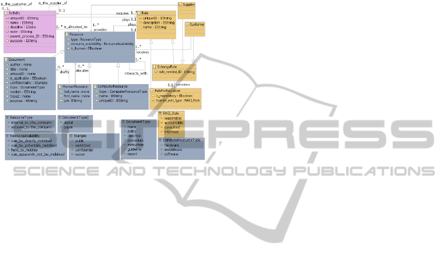
A meta-model is proposed to describe all
concepts, relationships, constraints and rules used to
guide the steps described in Section 2 and
particularly modelling activities. To illustrate our
point, an extract of this meta-model is shown in
Figure 3.
Figure 3: Example of meta-model (extract).
Nevertheless, this meta-model is not self-
sufficient: it must be completed with a textual
description of each class, attribute and relationship
in order to help the understanding of the modeller.
Furthermore, to ensure the syntactical consistency of
the models built by the deployment team, a graphical
representation of each class and relationship must
also be defined.
All elements constituting the conceptual
framework may evolve or be adapted according to
the results of their application in a given company.
3.2 Modelling Tools
The conceptual framework provides the basis for all
modelling work. However, to support it, the
deployment team needs a modelling tool including:
a modelling workbench enabling to graphically
represent the processes' components,
a complementary tool for the description of
models elements.
Therefore, among the various needs this modelling
tool has to meet, we can mention:
N1: the modelling workbench must be able to
read the meta-model and its graphical
representation to constraint the building of
models accordingly.
N2: the tool must be open-ended. Indeed, as
said previously, the meta-model used as a basis is
continuously improved as its application in company
goes forward. So, any change in the conceptual
framework must be performed quickly and must not
induce instability of the modelling tool .
N3: for interoperability purpose, the tool must be
“easily" connectable. Indeed, it must be compatible
with other tools necessary for the deployment even
if they are not known yet. Compatibility with the
modelling tool currently used within the company
must be considered.
N4: the tool must be able to support standard
modelling languages such as the Unified Modeling
Language (UML) or the Business Process Modeling
Notation (BPMN) (OMG, 2011) (Wohed et al.,
2006) to facilitate the understanding of any person
who would read or annotate the model. Furthermore,
the tool must be able to extend these modelling
reference languages in order to add some required
parameters such as those necessary for the
interoperability appraisal.
N5: the models built with this tool must be in a
format which facilitates the use of workflow
engines for the management of the activities
described in these models.
N6: the tool must be maintained at least during
the design time. It is critical in the case of long-time
design cycles such as those of aircrafts for example.
N7: the tool must be able to manage multiple
versions of models and meta-model (configuration
management).
N8: the tool must be able to add documentation
about models and their elements.
All these needs induce difficulties to find a
commercial off-the-shelf framework and tools which
would be directly applicable and interoperable with
the meta-model. The Graphical Modelling
Framework (GMF) plug-in of Eclipse is proposed
and its principles are illustrated on Figure 4.
Let us take back all desired functionalities to check
the compliance of GMF:
N1: “the tool must use the defined meta-
model and graphical definition”. Considering the
functioning of GMF, this need is met.
N2: "the tool must be open-ended". The
functioning of GMF based on three separated layers
enables easy changes and lessens the risk of loss of
stability because of change.
N3: "the tool must be easily connectable".
This need is met since GMF is based on Extensible
Markup Language (XML) which is a standard
generic language for exchanges.
N4: "the tool must be able to support
standard modelling languages". GMF supports any
kind of modelling languages since the meta-model
and the graphical definition for its elements are
defined by the developer designing the modelling
ICSOFT 2011 - 6th International Conference on Software and Data Technologies
68
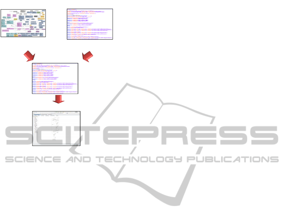
Domain model Graphical definition model
Mapping model
Modelling workbench
Graphical representation of the
elements of domain model
Meta-model: defined in xml
or with a graphical editor
Mapping between
Domain model and
Graphical
Definition Model
Eclipse
application with
drag&drop
elements for the
modeller
Figure 4: Basic elements constituting GMF.
workbench.
N5: "the tool must facilitate the
implementation of workflow engines". Here again,
thanks to XML, this need is met.
N6: "the tool must be maintained at least
during the design time". If the implementation of
GMF is done by company's employees, it is up to
the enterprise to manage the maintenance of the tool
and to ensure that maintenance skills are available
all over the design of its products.
N7: "the tool must manage versioning". This
functionality is not performed by GMF.
N8: "the tool enables to add documentation
about models and their elements". This
functionality is included in GMF.
Consequently, only the need "N7" is not
performed by GMF. However, this lack is not
critical since in the worst case the versioning of
models can at least be performed manually by the
modeller.
3.3 Tools Supporting Modelling
Activities
We introduced previously two notions: the
conceptual framework providing the set of concepts
and rules for the modelling and the modelling tool
providing required technical means. However, they
both do not assist the modeller in his modelling
work. Consequently, complementary tools have been
added in this deployment framework.
3.3.1 Tools Organizing Modelling Activities
During the preparation of the deployment, a lot of
models must be built, probably by different
modellers. Therefore, the framework for the
deployment must include a tool helping to allocate,
synchronize and monitor modelling activities. This
can be easily done with a workflow engine chosen
among those available on the market. Completing
the selection criteria specific to the company, the
following points can be considered.
First, for interoperability purpose, the tool must
be “easily" connectable in order to be compatible
with any other tools necessary for the deployment
even if they are not known yet.
Then, as a workflow engine can also be used to
manage deployed processes, we recommend using
the same tool in the two contexts to limit the number
of tools and thus the induced costs (licences,
training, etc.). Therefore, needs for the workflow
engine of the deployed processes must be considered
when choosing the one for modelling activities. An
example of these needs is the ability to communicate
with technical tools used to performed SE activities
(such as requirements management tools, design
architecture tools, etc.) in order to collect and share
the documents generated by them.
Finally, the possibility to use flexible workflows
rather than traditional workflows must be envisaged.
Indeed, contrary to traditional workflows where the
execution of the sequence offers no freedom and
where data are shared with difficulty, in flexible
workflows, activities can be anticipated and
collaborative work is increased thanks to shared data
(Grigori et al., 2000). To this end, easiness of
translations from BPMN to the Business Process
Execution Language (BPEL) (OASIS, 2007)(White,
2005) must be considered.
3.3.2 Tools Facilitating Modelling Activities
To assist the team members in their modelling
activities, we have introduced in our framework
tools providing them with:
- partial views of the meta-model with only the
concepts and relationships they need at a given
time and formatted with the up-to-date defined
graphical representation of concepts.
- generic models such as models of processes,
resources, or resources' roles since reuse or
instantiation of models is time-saving.
- modelling good practices and advices collected
notably from enterprise modelling.
The methodological aspects of these tools are
currently under development.
A MODEL BASED SYSTEMS ENGINEERING PROCESSES DEPLOYMENT FRAMEWORK
69

3.4 Tool for the Interoperability
Appraisal
As presented in section 2, in order to define the SE
processes to deploy, the appraisal of the resource
abilities and capacities in terms of interoperability
must be realized notably to decide between two
equivalent resources.
To highlight the desired functionalities of the tool
for the interoperability assessment, let us consider a
simplified operational scenario
During its start-up, the tool loads from existing
process models, the resources already modelled.
Among them, the user selects the one(s) he needs
and selects the kind of assessment he wants to use. If
the tool does not have all information required to
assess the resource(s), it asks the user for
complementary information according to a questions
tree defined in the interoperability assessment
methodology. Once all data have been collected, the
tool adds them to a local version of the process
model which is submitted to the validation of the
person in charge of the model. The tool generates a
report to the user containing the details of the
assessment, the analysis of these results and advices
to improve the interoperability of the resource(s). A
copy of this report is archived. Finally, if the person
in charge of the model validates the modification
proposed by the tool, the new version of the process
model is included in the models database and the
previous one is archived. If the modeller disagrees
with the modifications proposed by the tool he can
either achieve the necessary changes or reject the
propositions.
A tool such as described in the operational
scenario does not exist and has thus to be developed
to meet the deployment team's needs. Like for the
other tools, it must be open-ended and easily
connectable. It must also be able to detect if the user
has entered unexpected data.
4 CONCLUSION AND FUTURE
WORK
In this paper, we present an innovative approach to
deploy systems engineering processes. Its originality
is the fact that it is based on models, enabling thus to
build a bridge between systems engineering and
enterprise modelling. This is a turnkey approach
delivered with a full software framework designed to
assist the team in charge of the deployment. It
includes all technical means needed to build the
required models but also a tool enabling to appraise
the interoperability capability of the resources to be
involved in the new process to deploy. The strength
of this framework is its design thought to have a set
of consistent, interoperable and open-ended tools
limiting evolution problems and compatibility
problems with tools already existing in the company.
Thus, this equipped approach is a contribution to the
introduction of systems engineering in companies
dealing with the three classical dimensions of
interoperability: conceptual, organisational, and
technical.
REFERENCES
Chapurlat, V., & Braesch, C., 2008. Verification,
validation, qualification and certification of enterprise
models: Statements and opportunities. Computers in
Industry, 59(7), 711 – 721. Enterprise Integration and
Interoperability in Manufacturing Systems.
Estefan, J., 2008. Survey of Model-Based Systems
Engineering (MBSE) Methodologies. Tech. rept.
INCOSE.
Grigori, D., Skaf-Molli, H., & Charoy, F. 2000. Adding
flexibility in a cooperative workflow execution engine.
Pages 227–236 of: 8th International Conference on
High Performance Computing and Networking Europe
- HPCN Europe 2000, Amsterdam, Hollande.
Springer.
INCOSE, 2010. Systems Engineering Handbook - A guide
for system life cycle processes and activities - v3.2.
ISO, 2010. ISO/DIS 11354-1 - Advanced automation
technologies and their applications - Part 1:
Framework for enterprise interoperability.
ISO/IEC, 2008. ISO/IEC 15288:2008 - Systems
engineering - System life cycle processes.
OASIS, 2007. Web Services Business Process Execution
Language Version 2.0. Tech. rept.
OMG, 2011. Business Process Model and Notation
(BPMN) Version 2.0. Tech. rept.
Vernadat, F., 1996. Enterprise modeling and integration:
principles and applications. Kluwer Academic
Publishers.
White, Stephen A., 2005. Mapping BPMN to BPEL
Example. Tech. rept. IBM.
Wohed, P., Dumas, M., Hofstede, A. H. M. Ter, &
Russell, N., 2006. On the Suitability of BPMN for
Business Process Modelling. Pages 161–176 of: In
Proceedings 4th International Conference on Business
Process Management (BPM 2006), LNCS. Springer
Verlag.
ICSOFT 2011 - 6th International Conference on Software and Data Technologies
70
