
DESIGN OF A PROGRAMMABLE BIOELECTRICAL IMPEDANCE
SYSTEM FOR BIOMEDICAL APPLICATIONS
Daniela Loi
1
, Gianfranco Marongiu
1
, Claudia Palla
1
, Gianmarco Angius
2
and Michele Gallamini
1
1
RGMD SpA, R&D Department, Sestu, Italy
2
Department of Electrical and Electronic Engineering, University of Cagliari, Cagliari, Italy
Keywords:
Bioelectrical impedance analysis, Multifrequency measurement, Acupuncture research.
Abstract:
The design of a portable, versatile and programmable bioelectrical impedance system is presented. The device
uses inexpensive off-the-shelf components to perform multi-frequency current injection and voltage measure-
ments through skin electrodes. The impedance measurement system can be configured as multi-frequency
bioelectrical impedance analyzer as well as acupuncture point detector, for localizing pathologically changed
acupuncture points on the body. In order to improve the accuracy and the flexibility of the measurements, a
programmable wide frequency bandwidth current source has been designed. It allows to generate sinusoidal
and square waveforms with a frequency up to 1MHz and amplitude values in the range of [12µA
pp
−1.2mA
pp
].
The measured signals can be amplified with a programmable gain and converted with 16 bits of resolution be-
fore being transmitted to a PC through USB transmission for further processing.
1 INTRODUCTION
Multi-frequency bioelectrical impedance analysis
(MBIA) is a non-invasive technique to assess body
composition and to determine fluid distribution across
cell membranes, based on the property of tissues
to conduct electrical alternating current (Kyle et al.,
2004). At low frequencies (lower than 100kHz) cell
membranes represent a barrier to the flow of elec-
tric current, so bioelectrical impedance measurement
can be used to estimate extra-cellular water (ECW).
In contrast, at frequency over 100kHz, electric cur-
rent permeates cell membranes and flows through
cell so, bioelectrical impedance can be used to es-
timate total body water (TBW). Changes in tissue
perfusion can cause dehydration, arterial hypoten-
sion, edema and cerebral intraventricular hemorrhage
(Mayer et al., 2005). These events induce variations
of the bioimpedance electrical characteristics, whose
on-line monitoring could be of great diagnostic rele-
vance in clinical investigation and patient care (Ric-
ciardi and Talbot, 2007). In line with this aim, sev-
eral bioelectrical impedance instruments have been
developedrecently, mostly based on the Direct Digital
Synthesis (DDS) technique for multi-frequency stim-
ulus signal generation (Seoane et al., 2008; Cheng
et al., 2006; Hartov et al., 2000). Moreover, ac-
cording to several studies and research experiments,
skin impedance measurements can be used also to lo-
cate acupuncture points (APs) and to guide diagno-
sis and treatment strategies on those points (Reichma-
nis et al., 1976). The assumption that the skin resis-
tance shows differencesamong APs and the surround-
ing tissues, is under debate and is currently controver-
sially discussed in the literature (Kramer et al., 2009).
Consequently, a low-cost device has been developed
in order to evaluate the phenomenon of electrical skin
resistance changes before and during acupuncture and
to obtain precise and objective information about this
topic. In addition, the system can be configured as
multi-frequency bioelectrical impedance analyzer for
BIA purpose, allowing rapid and accurate measure-
ment of the electrical impedance over a wide fre-
quency range.
2 SYSTEM DESIGN
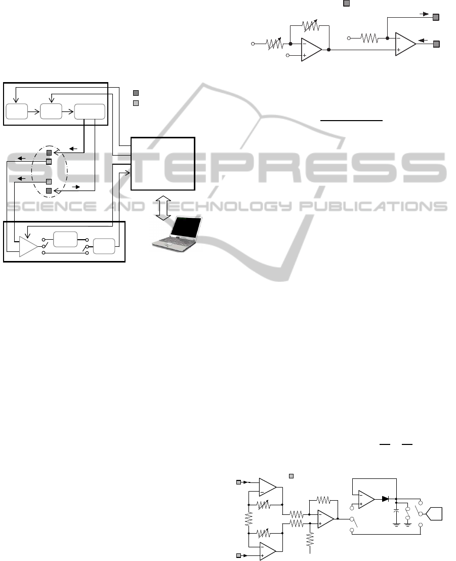
A schematic diagram of the bioelectrical impedance
system is shown in Figure 1. Basically, it consists
of four main parts: electrodes, multi-frequency cur-
rent source, voltage measurement circuitry and digital
system controller. A painless and constant amplitude
electrical current I
inj
flows through tissue via a pair of
current electrodes. The voltage drop across tissue im-
307
Loi D., Marongiu G., Palla C., Angius G. and Gallamini M..
DESIGN OF A PROGRAMMABLE BIOELECTRICAL IMPEDANCE SYSTEM FOR BIOMEDICAL APPLICATIONS.
DOI: 10.5220/0003736203070310
In Proceedings of the International Conference on Biomedical Electronics and Devices (BIODEVICES-2012), pages 307-310
ISBN: 978-989-8425-91-1
Copyright
c
2012 SCITEPRESS (Science and Technology Publications, Lda.)
pedance is detected by a pair of voltage electrodes,
amplified by a programmable-gain instrumentation
amplifier and then, directly digitized using a 16-bit
analog-to-digital converter or first sent to the peak de-
tector input, in order to convert only peak levels of
the signal. The bioelectrical impedance system has
been realized using a COTS-based (Commercial Off-
the-Shelf) design and it is supplied by the +5V USB
power bus.
Current Source Module
Voltage Measurement
Module
Tissue
USB
Digital
Module
DDS
PGA
V/I
Converter
µ
-CONTROLLER
for
Signal generation
Data transmission
Powering
I
inj
+
I
inj
-
Peak
Detector
V
meas
+
V
meas
-
IA
-
+
ADC
Current Electrodes
Voltage
Electrodes
Figure 1: Block diagram of the bioelectrical impedance sys-
tem.
Current Source Module. The current source mod-
ule has been designed using a direct digital synthe-
sizer (DDS) in combination with a programmable
variable gain amplifier/attenuator and a V/I converter.
The Analog Devices DDS chip AD9833 has been
chosen for its ability to generate constant ampli-
tude sine waves in the frequency range from 0Hz
to 12.5MHz. Since the AD9833 architecture does
not provide waveform amplitude adjustment, a pro-
grammable attenuation/amplifying circuit have been
integrated in the circuit in order to make use of the
entire voltage range (0V −3V). By means of two digi-
tally controlled potentiometers R
1
and R
2
(ISL22316,
Intersil), DDS output signal can be amplified or at-
tenuated in amplitude from −47dB to +47dB. The
voltage-to-current (V-I) converter has been realized
using a simple operational amplifier (OPA343, Texas
Instruments) in a non-inverting configuration, using
the tissue impedance as feedback resistor. It converts
the amplified/attenuated voltage signal into the con-
trolled current I
inj
required for the tissue excitation.
As shown in equation 1, the excitation current is in-
dependent of the tissue resistance and can reach val-
ues from 12µA
pp
to 1.2mA
pp
. Excitation levels and
frequencies are digitally controllable from a personal
computer via a Universal Serial Bus (USB) controller
interface.
OPA343
R1
R2
OPA343
Current Electrodes
V
outPGA
V
ref
I
inj
+
I
inj
-
R3
(1.65 k
W
)
V
ref
V
sine
Figure 2: PGA and V-I converter circuits.
I
inj
=
(V
outpga
−V
ref
)
R
3
(1)
Voltage Measurement Circuitry. The voltage mea-
surement module is composed of a programmable-
gain instrumentation amplifier (IA), a peak detec-
tor and a 16-bit successive-approximation analog-to-
digital converter (ADC). As shown in Figure 3, a
three-amplifier implementation of the instrumentation
amplifier has been designed. The output signal V
meas
is indicative of a difference between the pair of in-
put signals (V
+
in
and V
−
in
) received from the two detec-
tion electrodes, as reported in equation 2. The volt-
age gain of the circuit is programmed by a digitally
controlled potentiometer R
4
(ISL22316, Intersil), and
varies from 1.8 to about 200. The voltage V
meas
mea-
sured by the instrumentation amplifier, can be directly
converted into digital samples using 16-bit AD7694
(Analog Devices) ADC or sent to the peak detector
input, in order to convert only peak levels of the signal
when very high frequencies are used. The AD7694,
in fact, can only reliably convert signals below 5kHz.
The peak detector has been implemented using an op-
amp configured as a voltage follower, whose output
is used to charge the capacitor C
1
through diode D
1
.
Once that the chosen signal is converted, it is sent to
the PC to be stored in a data file.
V
meas
= (V
+
in
−V
−
in
) · (1 + 2·
R
4
R
5
) ·
R
7
R
6
(2)
OPA343
R6
R7
R7
R6
OPA343
OPA343
R4
R4
R5
V
in
+
V
in
-
+
Voltage Electrodes
V
ref
(2 k
Ω
)
V
meas
(2 k
Ω
)
(1 k
Ω
)
OPA343
V
peak
D1
C1
AD7694
ADC
Figure 3: Voltage measurement circuitry.
BIODEVICES 2012 - International Conference on Biomedical Electronics and Devices
308
Digital System. The digital module is responsible
of monitoring several aspects of the system. It is
based on the Universal Serial Bus (USB) controller
PIC18F4550 (Microchip), chosen principally for its
low cost and relative ease of programming. The func-
tion of the microcontroller is to manage communi-
cation between PC and modules of the bioelectrical
impedance system. The PIC18F4550 contains a full-
speed and low-speed compatible USB Serial interface
Engine that allows fast communication between any
USB host and the microcontroller itself.
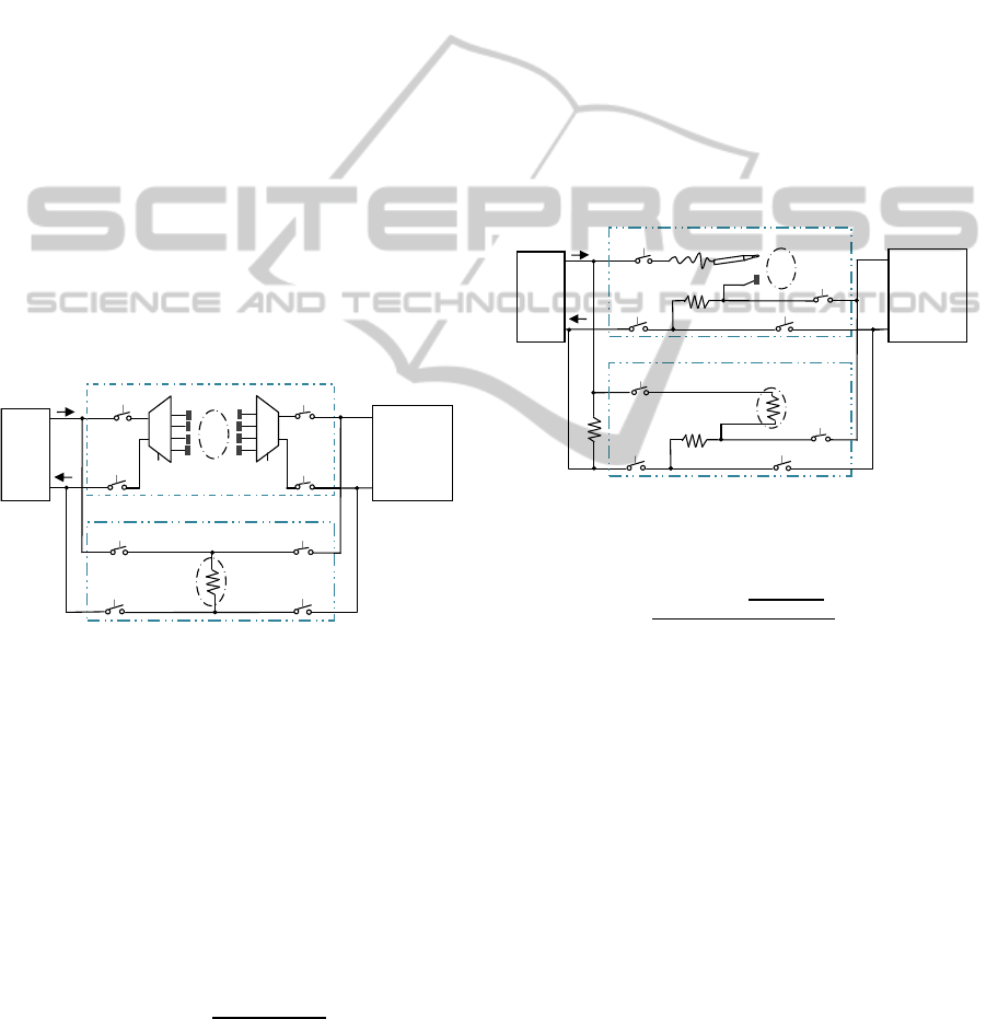
3 OPERATING MODES
The system supports two different operating modes:
multi-frequency bioelectrical impedance analysis and
acupuncture stimulation with point finding. In order
to evaluate circuitry functionalities before in-vivolab-
oratory trials on animals, two additional Test operat-
ing modes have been integrated in the system. The
dummy resistor R
tissue
simulates the tissue impedance
during the testing operation modes.
I
inj
+
I
inj
-
Current
Source
Voltage
Measurement
Circuit
V
in
+
V
in
-
Tissue
Mode1
Mode1
Mode1
R
tissue
TestMode1
TestMode1
TestMode1
TestMode1
BIA Test Mode
BIA Mode
Sel1
M
1
M
2
Sel1
Mode1
Figure 4: System reconfigurability: switch network for BIA
and test.
When the BIA operating mode is selected, the sys-
tem is enabled to estimate resistance values from each
arm and leg. The tissue resistance R
tissue
is given
by equation 3. Typically the electrical resistivity of
human tissues, except fat and bone, varies from 150
to 675Ω in the frequency range [100Hz − 10MHz]
and the whole-body impedance value is around 500Ω
(Faes et al., 1999). Thus considering this range, a re-
sistance of 499Ω has been chosen to simulate the tis-
sue impedance during BIA Test operating mode.
R
tissue
=
(V
in
+ −V
in
− )
I
inj
(3)
During the APs research working mode, a probe
electrode is passed over the skin while a second elec-
trode is held in the hand of the patient to complete an
electrical circuit therethrough. The tissue impedance
presented between the two electrodes will depend
on the placement of probe electrode on the patient’s
body. As the probe electrode is passed over the pa-
tient’s skin, the detected impedance will vary nar-
rowly around a nominal magnitude with substantial
variations occurring within skin moisture conditions.
Significantly variations in tissue impedance, however,
will be detected only when the pointed electrode lo-
calizes an acupuncture point. The tissue resistance
R
tissue
in the APs research operating mode is given by
equation 4. Since skin impedance at APs can ranges
from 10kΩ to 10MΩ (Colbert et al., 2008), to verify
the APs finder electronic system functionalities, the
tissue impedance has been replaced with a resistive
component of 49.9kΩ in the Acupuncture Research
Test operating mode.
I
inj
+
I
inj
-
Current
Source
Voltage
Measurement
Circuit
V
in
+
V
in
-
Tissue
Mode2
Mode2
Mode2
Mode2
R
tissue
TestMode2
TestMode2
TestMode2
TestMode2
Acupuncture Research Test Mode
Acupuncture Research Mode
R
a
R
a
R
b
100
Ω
499
Ω
Figure 5: System reconfigurability: switch network for
acupuncture research and test.
R
tissue
=
R
b
· (I
inj
−
V
in
+
−V
in
−
R
a
)
V
in
+ −V
in
−
· R
a
− R
a
(4)
4 PRELIMINARY RESULTS
A preliminary phase of experiments has been carried
out configuring the circuitry in test modes with the
aim of validating the electronic system design. The
BIA test has been conducted by injecting a stimu-
lus current of 600µA
pp
at three different frequencies
through R
tissue
and by measuring the voltage drop
across it when a gain of 2 is set in the IA circuit.
The results are expressed graphically in Figure 6 and
demonstrate system’s ability to measure according to
equation 3, a magnitude impedance of 499Ω in a wide
range of current signal frequencies. The same value
(V
in
+ −V
in
− ) = 299.4mV is in fact obtained at 10Hz,
100Hz and 1kHz. The APs test has been performed
by setting the current source to generate a stimula-
tion signal I
inj
of 990µA
pp
at 50kHz. The value of
DESIGN OF A PROGRAMMABLE BIOELECTRICAL IMPEDANCE SYSTEM FOR BIOMEDICAL APPLICATIONS
309
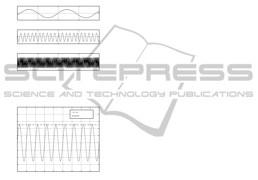
(V
in
+ − V
in
− ) can be reconstructed with good accu-
racy by subtracting the offset (1.5V) from the peak
detector output and multiplying the result by two.
As shown in Figure 7 a value of 0.978mV
pp
is ob-
tained for (V
in
+ − V
in
− ). Substituting this value into
equation 4, as expected the resulting impedance is
R
tissue
≃ 49, 9kΩ.
0 0.05 0.1 0.15 0.2
1
1.5
2
Time [sec]
Amplitude [V]
0 0.05 0.1 0.15 0.2
1
1.5
2
Time [sec]
Amplitude [V]
0 0.05 0.1 0.15 0.2
1
1.5
2
Time [sec]
Amplitude [V]
Figure 6: Results of BIA test mode operation: voltage
V
meas
= 2 ∗ (V
in
+
− V
in
−
) measured at 10Hz, 100Hz and
1kHz.
0 0.2 0.4 0.6 0.8 1 1.2 1.4 1.6 1.8
x 10
−4
1.4992
1.4994
1.4996
1.4998
1.5
1.5002
1.5004
1.5006
1.5008
Time [sec]
Amplitude [V]
Vpeak
Vin
+
− Vin
−
Figure 7: Peak detector output voltage when a current I
inj
of 990µA
pp
at 50kHz is provided as stimulus and the re-
spective signal (V
in
+
−V
in
−
) reconstruction.
5 CONCLUSIONS
A portable system for multi-frequency bioelectrical
impedance analysis and acupuncture point stimula-
tion and detection is presented. The device has been
designed and implemented using COTS-based elec-
tronics. Preliminary results demonstrate the capabil-
ity of providing electrical stimulation of skin, inject-
ing sinusoidal current pulses with programmable pa-
rameters. Since it has not still been possible to real-
ize in-vivo experiments, preliminary tests have been
performed using a dummy resistor to simulate the tis-
sue impedance. The measurement system is able to
record signals below 100µV
pp
at low and high fre-
quencies. It also provides programmable amplifica-
tion to realize highly sensitive measurements.
ACKNOWLEDGEMENTS
This work was funded by the Italian Ministry of Ed-
ucation, University and Research (MIUR) under the
Project MEDTECH.
REFERENCES
Cheng, K. S., Chen, C. Y., Huang, M. W., and Chen,
C. H. (2006). A multi-frequency current source for
bioimpedance application. In Int. Special Topic Conf.
Info. Technol. Biomedicine (Ioannina, Greece).
Colbert, A. P., Yun, J., Larsen, A., Edinger, T., Gregory,
W. L., and Thong, T. (2008). Skin impedance mea-
surements for acupuncture research: Development of
a continuous recording system. eCAM, 5(4):443–450.
Faes, T., der Meij, H. A. V., Munck, J. C. D., and Heethaar,
R. M. (1999). The electric resistivity of human tissues
(100 hz-10 mhz): a meta-analysis of review studies.
Physiological Measurement, 20(4):R1–10.
Hartov, A., Mazzarese, R. A., Reiss, F. R., Kerner, T. E.,
Osterman, K. S., Williams, D. B., and Paulsen, K. D.
(2000). A multichannel continuously selectable mul-
tifrequency electrical impedance spectroscopy mea-
surement system. IEEE transactions on biomedical
engineering, 47(1):49–58.
Kramer, S., Winterhalter, K., Schober, G., Becker, U.,
Wiegele, B., Kutz, D. F., Kolb, F. P., Zaps, D., Lang,
P. M., and Irnich, D. (2009). Characteristics of elec-
trical skin resistance at acupuncture points in healthy
humans. The Journal of Alternative and Complemen-
tary Medicine, 15(5):495–500.
Kyle, U. G., Bosaeus, I., DeLorenzo, A., Deurenberg,
P., Elia, M., Gomez, J. M., Heitmann, B. L., Kent-
Smith, L., Melchior, J., Pirlich, M., Scharfetter, H.,
Schols, A. M., and Pichard, C. (2004). Bioelectrical
impedance analysis - part i: review of principles and
methods. Clinical Nutrition, 23(5):1226–1243.
Mayer, M., Brunner, P., Merwa, R., and Scharfetter, H.
(2005). Monitoring of lung edema using focused
impedance spectroscopy: a feasibility study. Physi-
ological Measurement, 26:185–192.
Reichmanis, M., Marino, A. A., and Becker, R. O. (1976).
D.c. skin conductance variation at acupuncture loci.
American J. Chinese Med., 4(1):69–72.
Ricciardi, R. and Talbot, L. (2007). Use of bioelectrical
impedance analysis in the evaluation, treatment, and
prevention of overweight and obesity. J. Am. Acad.
Nurse Pract., 19(5):235–241.
Seoane, F., Ferreira, J., Sanchez, J. J., and Bragos,
R. (2008). An analog front-end enables electrical
impedance spectroscopy system on-chip for biomedi-
cal applications. Physiological Measurement, 29:267–
278.
BIODEVICES 2012 - International Conference on Biomedical Electronics and Devices
310
