DYNAMIC RESPONSE ANALYSIS OF MULTIBODY SYSTEM
IN DISCRETE EVENT SIMULATION
Namkug Ku
1
, Sol Ha
1
, Myung-Il Roh
2
and Kyu-Yeul Lee
1
1
Seoul National University, Shinlim-Dong Kwanak-Gu, Seoul, Korea
2
University of Ulsan, Daehak-ro, Nam-gu, Ulsan, Korea
Keywords: Dynamic response analysis, Multibody system, Discrete event simulation.
Abstract: There are several kinds of mechanical systems that are under event-triggered conditions. For the dynamic
analysis of such mechanical systems, a simulation program that can generate equations of motion for
mutibody systems in the discrete-event simulation framework was developed. For complex multibody
systems, a dynamics kernel was developed to generate the equations of motion for multibody systems based
on multibody dynamics. To generate the equations of motion, the recursive formulation method was used.
Using the developed dynamics kernel, the dynamic responses of multibody systems can be carried out under
continuous conditions. The general multibody dynamics kernel, however, cannot deal with discontinuous-
state variables and event-triggered conditions. The multibody dynamics kernel, therefore, was integrated
into the discrete-event simulation program to deal with multibody systems in discontinuous environments.
The discrete-event simulation program was developed based on the discrete-event system specification
(DEVS) formalism, which is a modular and hierarchical formalism for analyzing systems under event-
triggered conditions.
1 INTRODUCTION
In many engineering fields, the need for accurate
dynamic-response analysis using a simulation tool is
increasing. Especially in the shipbuilding industry,
there are various types of mechanical systems that
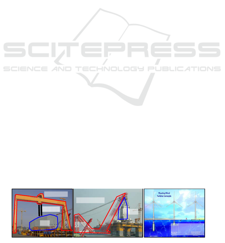
have to be analysed. Fig. 1 shows three examples of
such mechanical systems. Fig. 1(a) shows a goliath
crane, which is used to lift and transport heavy loads
and important facilities in shipyards. Fig. 1(b) shows
a floating crane, whose capacity is usually greater
than that of the goliath crane. As shown in the figure,
unlike the goliath crane, the floating crane is
operated on the sea. Fig. 1(c) shows floating
offshore wind turbines. All of these facilities are
mechanical systems that have to be analysed in their
dynamic aspects for accurate design.
The mechanical systems shown in Fig. 1 can be
considered as multibody systems, which are
collections of interconnected rigid bodies, consistent
with various types of joints that limit the relative
motion of pairs of bodies. Planners of shipbuilding
process, therefore, use commercial programs when
they receive requests for dynamic-response analysis.
These methods, however, have some limitations. As
the commercial programs for dynamic analysis are
Figure 1: Various types of mechanical systems in the shipbuilding industry: (a) goliath crane; (b) floating crane; and (c)
floating offshore wind turbines.
(b)
(a)
Load
Goliath Crane
Wire rope
Floating Crane
Load
(c)
Floating Offshore
Wind Turbines
447
Ku N., Ha S., Roh M. and Lee K..
DYNAMIC RESPONSE ANALYSIS OF MULTIBODY SYSTEM IN DISCRETE EVENT SIMULATION.
DOI: 10.5220/0003760804470453
In Proceedings of the 1st International Conference on Operations Research and Enterprise Systems (ICORES-2012), pages 447-453
ISBN: 978-989-8425-97-3
Copyright
c
2012 SCITEPRESS (Science and Technology Publications, Lda.)

usually developed for general purposes, they may
not be suitable for the various requirements of
process planning in shipbuilding.
For instance, the block-lifting and transport
process, which is carried out by a goliath or floating
crane, consists of several discontinuous stages, such
as hoisting-up, transport, and hoisting-down.
Meanwhile, most of the commercial programs for
multibody dynamic analysis cannot deal with
discontinuous-state variables as well as event- and
state-triggered conditions.
Therefore, the dynamics kernel was developed,
which can generate the equations of motion of
multibody systems for the accurate analysis of
dynamic systems. To deal with a multibody system
in a discontinuous environment, the multibody
dynamics kernel was integrated into the discrete-
event simulation program, which was developed
based on the discrete-event system specification
(DEVS) formalism. DEVS formalism is a modular
and hierarchical formalism for modelling and
analyzing systems under event-triggered conditions,
which are described by discontinuous-state variables.
2 RELATED WORKS
ADAMS (Automatic Dynamic Analysis of
Mechanical Systems) is a software system consisting
of a number of integrated programs that help an
engineer in performing three-dimensional kinematic
and dynamic analyses of mechanical systems
(Orlandea et al., 1977, Schiehlen, 1990). ADAMS
generates equations of motion for multibody systems
using augmented formulation. The user can define
any multibody system composed of several bodies
that are interconnected by joints. ADAMS supplies
various types of joints, such as fixed, revolute, and
spherical joints. Various external forces can also be
applied to multibody systems, but ADAMS cannot
handle discontinuous-state variables as well as
event- and state-triggered conditions.
ODE (Open Dynamics Engine) is an open-
source library for simulating multibody dynamics
(Smith, 2006). Similar to ADAMS, ODE derives
equations of motion for multibody systems using
augmented formulation. ODE cannot handle
discontinuous-state variables as well as event- and
state-triggered conditions.
RecurDyn is a three-dimensional simulation
software that combines dynamic-response and finite-
element analysis tools for multibody systems. It is
two to 20 times faster than other dynamic solutions
because of its advanced, fully recursive formulation.
Various joints and external forces can also be
applied to multibody systems, but RecurDyn cannot
handle discontinuous-state variables as well as
event- and state-triggered conditions.
On the other hand, Praehofer, Zeigler, et al.
(1990, 2000) proposed a modelling and simulation
method that can handle simulation models of
discrete events and times. They also developed a
simulation framework based on the proposed
method. In the case of discrete-event simulation, the
operation of a simulation system is represented as a
chronological sequence of events. Process or
material flow simulation systems and the like are
included in the category of discrete-event simulation.
On the other hand, in the case of discrete-time
simulation, the operation of a simulation system is
represented as the progress of time. State changes
occur only at discrete-time instants. Dynamic
simulation systems and the like are included in the
category of discrete-time simulation, but the
developed simulation framework focuses only on the
material flow simulation system of a workshop.
Thus, it was difficult for it to be applied to a large
factory such as a shipyard, and it was hard to use the
existing design and production information for the
simulation.
Many researches related to mutibody dynamic
analysis and discrete-event simulation have been
conducted, but they had some limitations in their
application to process planning in shipyards, as
mentioned earlier. To overcome these limitations, a
dynamics kernel that can automatically generate the
equations of motion of multibody systems was
developed and was integrated into the discrete-event
simulation program.
3 DEVELOPMENT
OF A MULTIBODY DYNAMICS
KERNEL FOR DYNAMIC
ANALYSIS
The facilities in shipyards, as shown in Fig. 1, are
multibody systems. For the modelling and dynamic
analysis of these multibody systems, a dynamics
kernel was developed. In this section, the coordinate
system and the properties of the rigid body will be
explained. The three formulations (augmented,
embedding, and recursive formulations) for the
derivation of equations of motion will be presented.
ICORES 2012 - 1st International Conference on Operations Research and Enterprise Systems
448

3.1 Construction of the Kinematics
of a Multibody System
3.1.1 Reference Frames and Properties
of the Rigid Bodies
To model the multibody system, the position and
orientation of the rigid bodies must be defined with
respect to the inertial reference frame. Because the
body fixed frames represent the position and
orientation of each rigid body, such frames should
be defined for every rigid body.
For each rigid body, moreover, it is necessary to
define the mass, mass moment of inertia about three
axes of the body fixed frame, and position of the
center of mass with respect to the body fixed frame.
3.1.2 Derivation of Equations of Motion
by using Recursive Formulation
The process of the derivation of equations of motion
for multibody systems with a large number of bodies
is difficult because many vectors and matrix
manipulations are involved. For this reason, various
formulations for the derivation of equations of
motion have been developed. In this study, recursive
formulation was used to derive equations of motion
because its computational efficiency is better than
that of the other formulations, such as the augmented
and embedding formulations.
1) Augmented formulation
One of the formulations for the derivation of
equations of motion is augmented formulation,
which is represented by the following equation:
Figure 2: Augmented formulation for the derivation of
equations of motion.
2) Embedding formulation
Another formulation for the derivation of
equations of motion is embedding formulation,
which is represented by the following equation. As
the dependent coordinates are eliminates in the
equations of motion, the constraint equations are not
explicitly shown.
Figure 3: Embedding formulation for the derivation of
equations of motion.
where is the mass and the mass moment of inertia
matrix and is the Coriolis and centrifugal matrix.
3) Recursive formulation
Figure 4: Recursive formulation for the derivation of
equations of motion.
A recently developed recursive algorithm for
formulating and solving equations of motion is
presented in this section. The equations of motion
used in recursive formulation are shown in Fig. 4
(Haug, 1992, Featherstone, 2008). Once the
velocities and accelerations of the generalized
coordinates are determined, the velocities and
acceleration of each body can be computed. Further,
recursive formulation can be utilized to find the
forces and moments acting on each link in a
recursive fashion, starting from the force and
moment applied to the rigid body, which is
connected to the end of the multibody system
(Sciavicco et al., 2000).
Although the equations are derived, the
operations required for implementation are
substantially difficult. Compared to the two other
formulations, however, augmented formulation is
easier in terms of operations because it uses absolute
coordinates.
d
−F
0
Te
d
⎡⎤⎡⎤
⎡⎤
=
⎢⎥⎢⎥
⎢⎥
⎢⎥⎢⎥
⎣⎦
⎣⎦⎣⎦
r
r
r
M
C
λ
CF
F
&&
(,) 0t =Cr
Constraint:
λ
: Lagrange Multiplier
()
0+=
rr
r
Cr Cr r
&& & &
Differentiation twice
r
C
r
:
Differentiation
C
with respect to
r
: Absolute Coordinates
M
: Mass and mass moment of inertia
e
F
: External force
(,) (,,)
e
+=Mq k q q F q q q
%% %
&& & & &&
,,,
TTeTe
where == =MMkMJJ JJ JqF F
%% %
&
&
J
: Velocity transformation matrix,
=rqJ
&&
q
: Generalized coordinate
M
: Mass and mass moment of inertia
e
F
: External force
1ii ii
q
−
=+vv S
&
*B
iiiiii
=+×fIavIv
T
iii
=τ Sf
1i i ii ii
qq
−
=+ +aa S S
&
&& &
1
Be
iiii
−
=−+ffff
i
v
: Velocity vector of body i (6 components)
i
a
: Acceleration vector of body i (6 components)
i
q
: Generalized coordinate (joint values)
i
S
: Velocity transformation matrix
i
I
: Mass and mass moment of inertia of body i
B
i
f
: Resultant force exerted on body i
e
i
f
: External force exerted on body i
i
f
: Force exerted on the joint i which is on body i
i
τ
: Force generated by joint i
(1)
(2)
(3)
(4)
(5)
DYNAMIC RESPONSE ANALYSIS OF MULTIBODY SYSTEM IN DISCRETE EVENT SIMULATION
449

As the embedding and recursive formulations
use relative coordinates, however, these
formulations need additional computation to
calculate the constraint force. Unlike augmented
formulation, moreover, the values that are associated
with relative motion between the bodies are
explicitly calculated using the embedding and
recursive formulations.
In the case of augmented formulation, the
number of equations of motion is 6n+p, which is
proportional to the number of bodies. As the
computational time for the calculation of the inverse
matrix is proportional to (6n+p)
3
, the complexity of
computation is O(n
3
) for solving the equations of
motion.
The number of equations of motion derived
using embedding formulation is 6n-p. As the
computation time for the calculation of the inverse
matrix is proportional to (6n-p)
3
, the complexity of
computation is O(n
3
) for solving the equations of
motion for the multibody system. As the matrix of
embedding formulation is smaller than that of
augmented formulation, the computational
efficiency of embedding formulation is better than
that of augmented formulation.
Unlike the two other formulations, recursive
formulation does not need to assemble a system of
equations of motion for each body as it is a recursive
method. Therefore, although the number of matrices
increases in proportion to the number of bodies n,
the size of the matrix of the equations of motion is
always 6×6. Consequently, the complexity of
computation is O(n) for solving the equations of
motion (Stejskal et al., 1996). In this study, due to
the computational efficiency, recursive formulation
was used to derive the equations of motion.
3.2 External Forces for the Dynamic
Response Analysis
Eq. 1 shows the external forces considered for the
dynamic response analysis. The external forces
consist of the hydrostatic forces with nonlinear
effects considering wave elevation, the linearized
hydrodynamic force, the mooring force, the
aerodynamic force, and the gravitational force, as
follows:
() () () ()
,,, , ,,
()
e
Hydrostatic Hydrodynamic Mooring
Aerodynamic Gravity
tt t=+ +
++
f
qqq
f
q
f
qq
f
q
fqf
&&& &&&
(1)
The module for calculating the external forces is
developed, and it is used for the dynamics kernel
(Ku et al., 2011).
4 MULTIBODY DYNAMICS
KERNEL IN DISCRETE EVENT
SIMULATION
In the previous section, the development of the
dynamics kernel was presented. However, it is hard
to deal with the discontinuous state variables, event
triggered conditions, and state triggered conditions
using the dynamics kernel. To overcome this
limitation, this study adopts the DEVS (Discrete
Event System Specification) formalism to develop
the simulation program.
4.1 DEVS (Discrete Event System
Specification) Formalism
The DEVS formalism, a set-theoretic formalism,
specifies ‘discrete event systems’ in a hierarchical
and modular form. The DEVS formalism consists of
two kinds of models: an atomic model and a coupled
model. The atomic model is the basic model and has
specifications for the dynamics of the model.
Formally, 7 components, which are state variables,
input events, output events, external transition
function, internal transition function, output function,
and time advance function, specify the atomic model.
The coupled model provides the method of assembly
of several atomic and/or coupled models to build
complex systems hierarchy. Each DEVS model,
either atomic or coupled, has correspondence to an
object in the real-world system to be modeled
(Zeigler, 1990, Zeigler et al., 2000).
However, the simulation progresses by changing
the state variables for not only every event but also
every unit time. Thus, the DTSS (Discrete Time
System Specification) model is combined with
DEVS model. The atomic model of DTSS is
composed of 7 components, which are state
variables, input events, output events, external
transition function, output function, integral function,
and state event function. The simulation model is
called ‘combined DEVS and DTSS simulation
model’. In this paper, for simplicity, the simulation
model will be called ‘DEVS simulation model’.
In this study, each facility shown in Fig. 1 is
modeled as an atomic model based on DEVS
formalism, and the coupled models are defined by
assembly of the several atomic models. In the next
sub-section, it will be explained how to define the
atomic model and the coupled model for the
simulation of the process planning in shipbuilding.
ICORES 2012 - 1st International Conference on Operations Research and Enterprise Systems
450
4.2 Modelling for the Simulation
of the Process Planning
in Shipbuilding
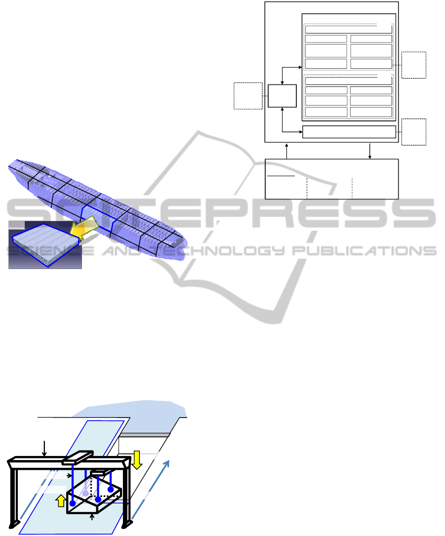
A ship is a huge structure made up of a large number
of hull structural parts called block. For example, A
deadweight 300,000 ton VLCC (Very Large Crude
oil Carrier, hereafter simply referred to as the ‘300K
VLCC’), which has a length, breadth, and depth of
about 320 m, 60 m, and 30 m, respectively, is
divided into a number of building blocks (e.g. about
200 building blocks in the case of the 300K VLCC)
as shown in Fig. 5.
Figure 5: Very large crude oil carrier and its block.
Each block is assembled in an assembly shop
near the dock, and the blocks are waiting on the PE
(Pre-Erection) area. Then, the blocks are moved into
the dock by using a goliath crane and welded
together according to a suitable sequence, called the
block erection, as shown in Fig. 6. Basically, the
construction process of a ship is similar to that of a
large product by use of Lego blocks.
Figure 6: Block-lifting and transport process.
Figure 7: DEVS simulation model for the block-lifting and
transport simulation.
Fig. 7 shows how to define the atomic model and
the coupled model for the simulation of the block-
lifting and transport process. The goliath crane, the
wire rope, and the block are defined as atomic
models. The each atomic model is connected with
the object function. Each object function has the
mathematical model of the atomic model. For
instance, the object functions of the goliath crane
and the block have their equations of motion, and
the object function of the wire rope has the equation
to calculate the tension considering its physical
properties, such as wire length and elongation. The
dynamics kernel is used as the object function for the
dynamic analysis. The atomic models of the
facilities exchange the external forces each other.
Beside these three models, also the scenario
manager, which manages discontinuous events, is
defined as an atomic model. We can see the event
list, composed of hoisting-up, transport, and
hoisting-down are defined for the block-lifting and
transport simulation. Every event contains the name
of the atomic model and the behavior. For example,
event #1 means that the atomic model ‘wire rope’
will carry out the event ‘hoisting-up’.
Fig. 8 shows that how the events are dealt by
sending messages between the atomic models. To
trigger event #1, the scenario manager sends the
massage ‘hoisting-up’ to the model ‘wire rope’ and
waits until the event is done by the model ‘wire rope’
(Fig. 8-a). After receiving the massage ‘done’ from
the model ‘wire rope’, event #2 will be triggered
with same sequence with event #1 (Fig. 8-b).
300,000 ton VLCC(Very Large Crude oil Carrier)
L=320m, B= 60m, D= 30m, T=20m
Block
Sea
Dock
PE area
Goliath Crane
Block
1) Hoisting-Up
2) Transport
3) Hoisting-Down
Wire rope
Goliath Crane
(Atomic Model)
Block
(Atomic Model)
‘Object
Function’
Equations
of
Motion
Wire
rope
(Atomic Model)
external force
external force
‘Object
Function’
Equations
to calculate
the tension
Simulation (Coupled Model)
Scenario Manager (Atomic Model)
Command Done
State Variable
Input Output
External Transition
Function
Output
Function
Time Advance
Function
Internal Transition
Function
DEVS
State Variable
Input Output
External Transition
Function
Integral
Function
State Event
Function
Output
Function
DTSS
‘Object
Function’
Equations
of
Motion
Event List
Event #1:
‘Wire rope’,
Hoisting-Up
Event #2:
‘Goliath Crane’,
Transport
Event #3:
‘Wire rope’,
Hoisting-Down
DYNAMIC RESPONSE ANALYSIS OF MULTIBODY SYSTEM IN DISCRETE EVENT SIMULATION
451
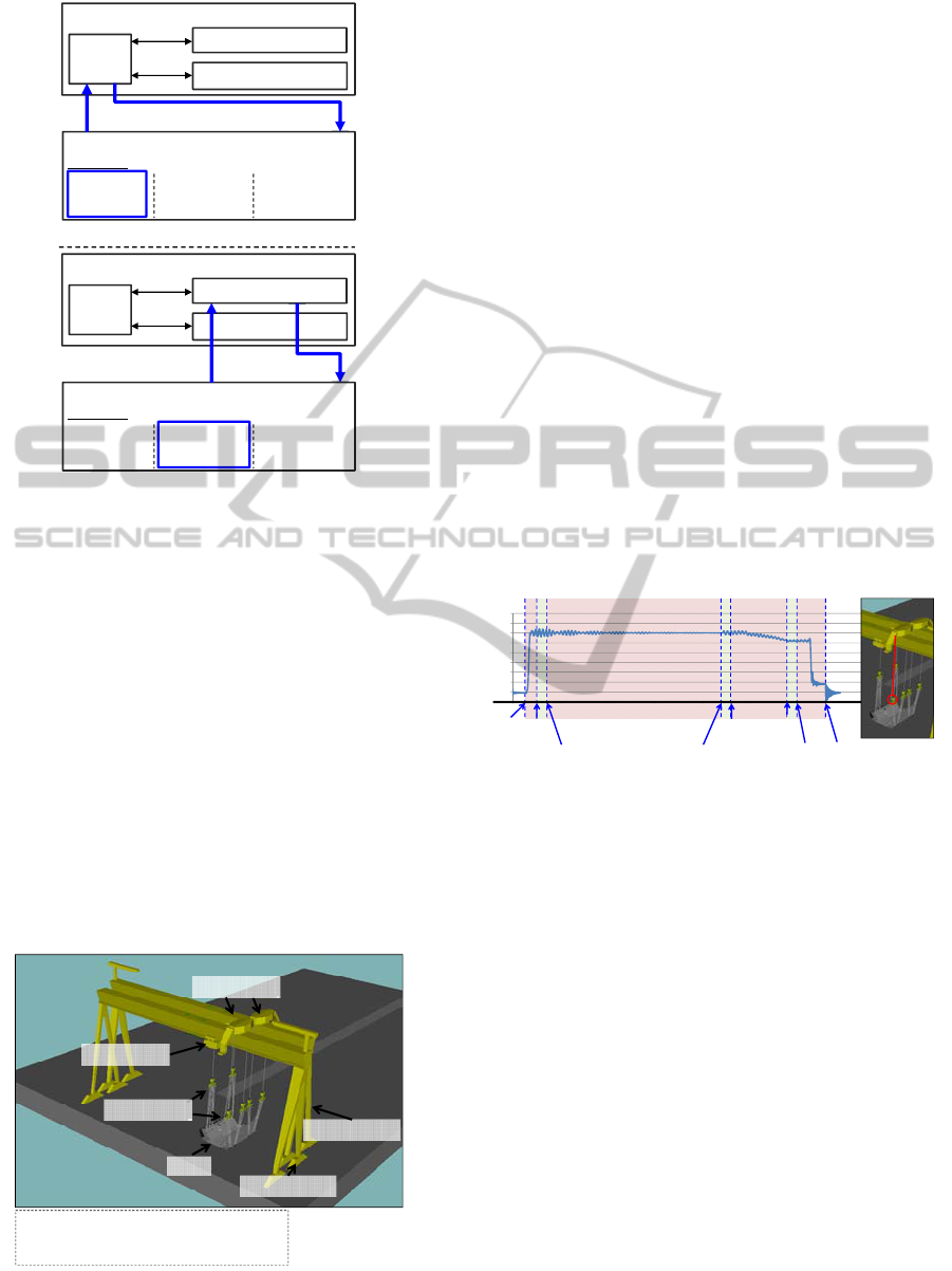
Figure 8: Sequence of sending messages between the
atomic models.
After modelling the goliath crane, wire rope, and
block using DEVS simulation model, shipbuilding
process, which is composed of several discontinuous
stages, can be easily simulated by defining the event
list.
5 APPLICATION TO
SIMULATION OF
BLOCK- LIFTING AND
TRANSPORT
This section presents an example of block-lifting and
transport and the result of the simulation.
Figure 9: The goliath cranes and block model in the
simulation of the block-lifting and transport.
The block-lifting and transport is carried out
using two goliath cranes, six block loaders, and one
block models. The goliath crane is composed of a
main body, upper trolley, and lower trolley. The
upper trolley and lower trolley are interconnected by
sliding joints with main body. The block loader
consists of two bodies, interconnected by revolute
joints with each other. As explained in sub-section
3.1.2, the equations of motion, i.e. the dynamics
model, are generated by using recursive formulation.
Fig. 9 shows the goliath cranes and block model in
the simulation of the block-lifting and transport.
Discrete events of the simulation are as
following;
a. Hoisting-up the block
b. Transportation of the block by moving the
goliath crane to the dock
c. Block turn-over: the process of turning the
block upside down.
d. Hoisting-down the block
Fig. 10 shows the simulation results. The graph
shows that tension of the wire rope, which is marked
with red.
Figure 10: Tension of the wire rope, which is marked with
red, calculated by using developed program.
The weight of the block is about 830ton.
Therefore, around 140ton is reasonable amount of
the tension, because there are total six wire ropes.
We can also see that dynamic responses are different
according to the events such as hoisting-up,
transportation, turn-over, and hoisting-down, which
means that the developed program can deal with the
discrete events.
6 CONCLUSIONS AND FUTURE
WORKS
A simulation framework was proposed and
implemented in this study. The dynamics kernel is
integrated into the discrete event simulation program
for the process planning in shipbuilding. To evaluate
the efficiency of the implemented simulation
program, it is applied to the simulation of the block-
Goliath Crane
(Atomic Model)
Block
(Atomic Model)
Wire
rope
(Atomic Model)
External
force
Simulation
(Coupled Model)
Scenario Manager
(Atomic Model)
Event List
Event #1:
‘Wire rope’,
Hoisting-Up
Event #2:
‘Goliath Crane’,
Transport
Event #3:
‘Wire rope’,
Hoisting-Down
Hoisting-Up
Done
External
force
Goliath Crane
(Atomic Model)
Block
(Atomic Model)
Wire
rope
(Atomic Model)
External
force
Simulation
(Coupled Model)
Scenario Manager
(Atomic Model)
Event List
Event #1:
‘Wire rope’,
Hoisting-Up
Event #2:
‘Goliath Crane’,
Transport
Event #3:
‘Wire rope’,
Hoisting-Down
Transport
Done
External
force
(a)
(b)
Upper Trolley
Goliath Crane 1
Block
Goliath Crane 2
Lower Trolley
Block Loader
- Main dimension of the goliath crane
Length: 177m, Height: 103.6m, Breadth: 51.434m
- Max Lifting Capacity of the goliath crane: 600 tons
- Weight of Block: 828.5ton
0
20
40
60
80
100
120
140
160
180
0 200 400 600 800 1000 1200 1400 1600
Time
(ton)
Transportation of
the block ends
Block
Turn-over
starts
Block
Turn-over
ends
Hoisting
-Up
starts
Hoisting
-Up
ends
Transportation of
the block starts
Hoisting
-Down
starts
Hoisting
-Down
ends
ICORES 2012 - 1st International Conference on Operations Research and Enterprise Systems
452

lifting and transport.
As future works, we will apply the developed
program to various simulation systems for process
planning in shipbuilding such as the simulation of
dynamic analysis of offshore structures and block
assembly processes in order to improve the
efficiency and applicability of the proposed
simulation program.
ACKNOWLEDGEMENTS
This work was supported by:
a) Industrial Strategic Technology Development
Program (10035331, Simulation-based
Manufacturing Technology for Ships and Offshore
Plants) funded by the Ministry of Knowledge
Economy (MKE, Republic of Korea);
b) Research Institute of Marine System Engineering
at Seoul National University;
c) Marine Technology Education and Research
Center, through the Brain Korea 21 project of Seoul
National University; and
d) SM-11: “A Study on the network-based
architecture of virtual system for the simulation of
underwater vehicles” of the Underwater Vehicle
Research Center.
REFERENCES
Orlandea, N., Chace, M. A., and Calahan, D. A., 1977, A
Sparsity-Oriented Approach to the Dynamic Analysis
and Design of Mechanical Systems-Part1&2, Journal
of Engineering for Industry, Transactions of the
ASME, Vol. 99, No. 3, pp 773-779.
Schiehlen, W., 1990, Multibody Systems Handbook,
Springer, pp 361-402.
Smith, R., 2006, Open Dynamics Engine v0.5 User Guide,
pp 15-20.
Zeigler B P, 1990, Object oriented simulation with
modular, hierarchical models: intelligent agents and
endomorphic systems, Boston: Academic Press.
Zeigler B P, Praehofer H, Kim T G, 2000, Theory of
modelling and simulation, 2nd ed., Boston: Academic
Press.
Featherstone, R. (2008), Rigid Body Dynamics, Springer,
pp 92-100.
Haug, E. J. (1992), Intermediate Dynamics, Prentice-hall,
pp 345-346.
Stejskal, V., Valasek, M. (1996), Kinematics and
Dynamics of Machinery, Marcel Dekker, Inc. pp 289.
Ku, N. K., Jo, A. R., Ha, S., Friebe, M., Cha, J. H., Park,
K. P., Lee, K. Y. (2010), Development of a Multibody
Dynamics Kernel for Motion Analysis of a Floating
Wind Turbine, The International Society of Offshore
and Polar Engineers 2011, Hawaii.
DYNAMIC RESPONSE ANALYSIS OF MULTIBODY SYSTEM IN DISCRETE EVENT SIMULATION
453
