VOLUME RENDERING STRATEGIES ON MOBILE DEVICES
Jos
´
e M. Noguera, Juan-Roberto Jim
´
enez, Carlos J. Og
´
ayar and Rafael J. Segura
Graphics and Geomatic Group of Ja
´
en, University of Ja
´
en, Campus Las Lagunillas, Edificio A3, 23071 Ja
´
en, Spain
Keywords:
Volume Rendering, Mobile Devices, GPU, Interactive Frame Rates.
Abstract:
This paper proposes and compares several methods for interactive volume rendering in mobile devices. This
kind of devices has several restrictions and limitations both in performance and in storage capacity. The paper
reviews the suitability of some existing direct volume rendering methods, and proposes a novel approach that
takes advantage of the graphics capabilities of modern OpenGL ES 2.0 enabled devices. Several experiments
have been carried out to test the behaviour of the described method.
1 INTRODUCTION
Volume visualization is a classic field of computer
graphics dedicated to render 3D scalar data. It is es-
sential to engineering and scientific applications that
require visualization of three-dimensional data sets.
Until recently, volume visualization has required
the use of a desktop computer. There are some cases
where this requirement cannot be fulfilled, for in-
stance, teaching labs, operating theatres, field trips,
informal meetings, etc. In these cases, it is of use
mobile devices, such as mobile phones, tablets or per-
sonal digital assistants (PDAs). However, interactive
3D rendering on mobile devices is a challenging task,
mainly due to the fact that they must be small and
powered by batteries. These two factors severely limit
their computing power and memory capacity.
This paper explores how their limited capabilities
affect the use of hand-held devices to perform inter-
active visualization of volumetric data. A novel strat-
egy is proposed, tackling the limitations and special
characteristics of mobile devices, that achieves inter-
active frame rates without recurring to external ren-
dering servers while keeping a good visual quality.
This strategy has been implemented and systemati-
cally compared with other methods in order to eval-
uate its performance and visual quality, see Figure 1.
This paper has been structured as follows. Sec-
tion 2 describes the previous work. Section 3 presents
our technique for volume rendering. Section 4 de-
scribes the implementation of a volume raycasting
technique we have used in our comparison. Section 5
shows and discusses the results under different sce-
narios. Finally, Section 6 concludes the paper.
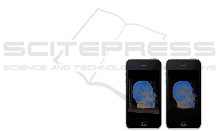
(a) (b)
Figure 1: Rendering of a skull model by using a) classic
volume ray casting, and b) our texture slicing proposal. Our
proposal doubles the performance providing a similar ren-
dering quality.
2 PREVIOUS WORK
A volume can be represented by using different ap-
proaches, the usual representation is a set of images/s-
lices that are parallel and evenly distributed across the
volume.
In the context of scientific visualization and vol-
ume rendering the transport equation usually neglects
illumination and is computed by composing colors
and opacities of the samples along a given line, for
a certain wavelength λ (Levoy, 1988):
447
M. Noguera J., Jiménez J., J. Ogáyar C. and J. Segura R..
VOLUME RENDERING STRATEGIES ON MOBILE DEVICES.
DOI: 10.5220/0003848604470452
In Proceedings of the International Conference on Computer Graphics Theory and Applications (GRAPP-2012), pages 447-452
ISBN: 978-989-8565-02-0
Copyright
c
2012 SCITEPRESS (Science and Technology Publications, Lda.)

C
λ
(x) =
n
∑
k=0
c
λ
(x + r
k
)α(x + r
k
)
n
∏
l=k+1
(1 − α(x + r
l
))
(1)
where C
λ
(x) is the final color at a given position x,
c
λ
(x +r
k
) is the color of the k
th
sample at position x +
r
k
inside the volume and α(x+r
k
) is its corresponding
opacity.
Several methods have been proposed to imple-
ment this expression. In general, existing methods
can be divided into two categories depending on the
way the volume is traversed: object order and image-
order approaches. For a deep study about volume ren-
dering techniques we refer to (Weiskopf, 2007).
Ray casting-based volume visualization is a clas-
sic image order method (Levoy, 1988) that defines the
color of each pixel in the image using the values of a
volume taken along a ray originated in that pixel.
Texture-based volume rendering techniques per-
form the sampling and compositing steps by render-
ing a set of 2D geometric primitives inside the vol-
ume (Ikits et al., 2004). These primitives are usually
known as proxy geometry or slices. Each vertex of
each primitive has texture coordinates that are used to
sample the volume texture. Blending is used to accu-
mulate color values according to corresponding opac-
ities. (Rezk-Salama et al., 2000) presented a tech-
nique known as 2D texture slicing, where the data set
is stored as a stack of 2D textures. On the other hand,
the 3D texture slicing technique (Ikits et al., 2004)
uses 3D textures and generates a view-aligned group
of polygons for each view direction. (Van Gelder and
Kim, 1996) avoided this geometry recomputation by
using a viewport aligned bounding cube that contains
the volumetric model. For each view direction the
texture coordinates have to be updated accordingly.
Concerning hand-held devices, interactive direct
volume visualization is still a largely unexplored field.
In these devices, 3D textures are supported through
an optional OpenGL ES 2.0 extension, which is not
available in most implementations, e.g., Apple’s mo-
bile devices.
First attempts tried to overcome the mobile de-
vices limitations by employing a server-based render-
ing approach. This approach relies on a dedicated
rendering server that carries out the rendering of the
volume and streams the resulting images to the mo-
bile client over a network (Lamberti and Sanna, 2005;
Jeong and Kaufman, 2007). Also following a server-
client scheme, (Zhou et al., 2006) employs a remote
server to precompute a compressed iso-surface, which
is sent to the mobile device allowing a faster render-
ing. Unfortunately, these server-based solutions re-
quire a persistent and fast network connection.
(Moser and Weiskopf, 2008) introduced an inter-
active technique for volume rendering on mobile de-
vices that adopts the 2D texture slicing approach. Au-
thors claim to achieve 1.5 frames per second (fps)
when rendering a very basic volumetric model con-
sisting of 633 voxels on a Dell Axim x51v device at a
resolution of 640×480 pixels.
(ImageVis3D, 2011) is an iOS application that
also uses the 2D texture slicing approach. While the
user is interacting the number of slices is drastically
reduced. At the end of an interaction a new image is
rendered with the whole set of slices. This rendering
step is carried out in the mobile device itself, or in a
remote server in case of complex models.
Recently, (Congote et al., 2011) have imple-
mented a ray-based technique using the WebGL stan-
dard. Authors have tested this implementation on
some Samsung Galaxy mobile devices, obtaining a
frame rate of around 2-3 fps.
3 OUR PROPOSAL
While today’s mobile GPUs offer features relatively
similar to those found on desktop PCs, their archi-
tecture gives preference to energy efficiency rather
than to pure performance. Therefore, we cannot ex-
pect to run long shaders originally written for desk-
top PCs on a mobile device at interactive frame rates,
even with low screen resolutions (Power VR, 2009).
Therefore, shaders for mobile devices must be specifi-
cally crafted to avoid complex computations and con-
ditional branches.
The techniques based on 3D texture slicing
(Van Gelder and Kim, 1996; Ikits et al., 2004) provide
a better rendering quality than the 2D texture slicing
approach. However, most OpenGL ES 2.0 implemen-
tations available in today’s mobile devices do not sup-
port 3D textures, so these two techniques do not apply
here. Also, the 3D texture slicing technique requires
the use of proxy geometry that has to be recomputed
every time the viewing angle varies. This representa-
tion is not the most appropriate for embedded devices
because the best performance on mobile GPUs is ob-
tained by drawing long batches of indexed triangles
cached in GPU’s memory (Power VR, 2009).
Therefore, our goal is to define a new technique
that overcomes these limitations while keeping the
same rendering quality.
3.1 Texture Mosaic
In order to provide the mobile GPU with the volumet-
ric data, the set of images that represents the model
must be combined into one 2D texture by tiling each
GRAPP 2012 - International Conference on Computer Graphics Theory and Applications
448
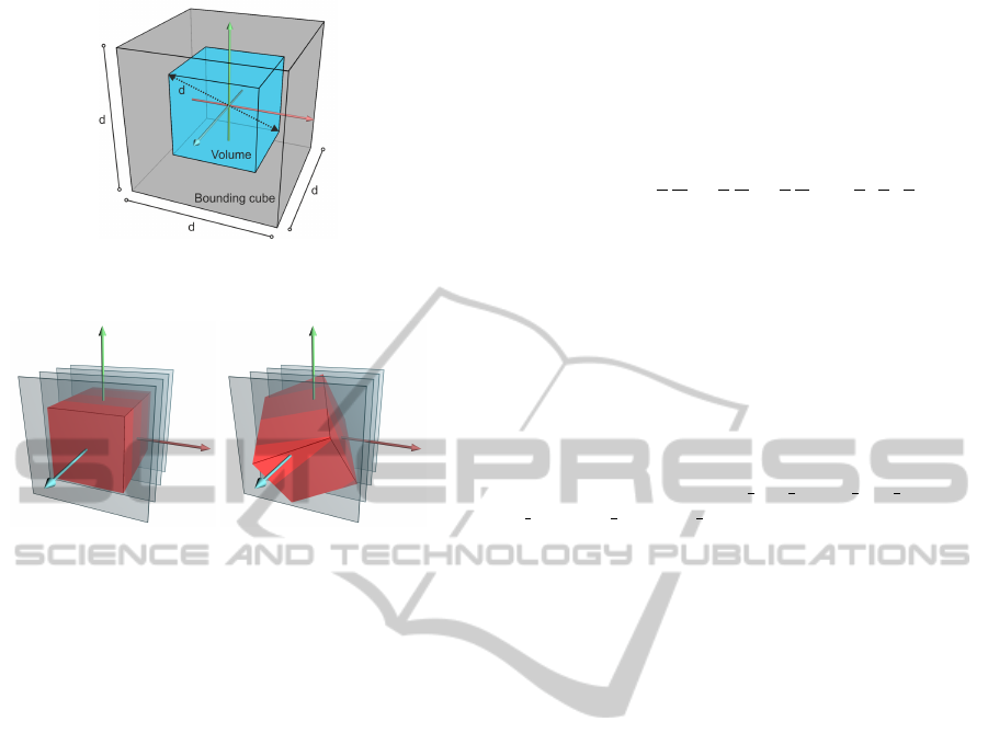
Figure 2: A bounding cube defined around a volume whose
diagonal is d.
Figure 3: The slices (shown in gray) are always perpendicu-
lar to the view direction. The texture coordinates are rotated
according to the desired view angle.
image one next to another in a mosaic configuration.
This mosaic texture can be generated in a preprocess-
ing step by means of the command-line tool montage
included in the open-source package ImageMagick.
In the shader, the correct texture coordinates can be
computed as described in (Congote et al., 2011).
3.2 Rendering the Volumetric Model
Our solution consists of a texture slicing approach
where a set of slices are projected perpendicular to the
view direction. Equation 1 is implemented by com-
positing these slices in a front-to-back order into the
framebuffer using alpha-blending.
Contrarily to the 3D texture slicing approach, in
our solution the geometry of the stack of slices is
computed once and remains stationary for the rest of
the process. Hence, it can be cached in GPU’s mem-
ory by means of a vertex buffer object (VBO) and
reused to draw every frame. VBOs are the preferred
method to send geometry to mobile GPUs (Power
VR, 2009) because they dramatically reduce the CPU-
GPU bandwidth and the number of draw calls.
However, we want to be able to render the model
from any angle without the visual artifacts and the
waste of memory suffered by the 2D texture slicing
approach. In order to render the slices perpendicu-
lar to any view direction, the volume is enclosed by a
cube of dimensions d
3
, being d the diagonal of the
volume, see Figure 2. This algorithm is based on
Gelder et al. (Van Gelder and Kim, 1996). The front
face of the cube remains perpendicular to the view di-
rection and, consequently, the slices defined over it
are view-aligned. The 3D texture coordinates without
rotation of the vertices of these slices are:
(s, t, r) = (±
1
2
d
X
, ±
1
2
d
Y
, ±
1
2
d
Z
) + (
1
2
,
1
2
,
1
2
)
where (X, Y, Z) are the dimensions of the texture rep-
resenting the volume. Then, this texture is properly
rotated according to the desired view angle using ap-
propriate transformation of the texture coordinates,
see Figure 3.
The proposed implementation works as
follows. First, blending should be enabled
and configured. The blending factors have
been defined in conjunction with code of the
shaders to accomplish Equation 1, by using
glBlendFuncSeparate(GL ONE MINUS DST ALPHA,
GL ONE, GL ONE, GL ONE).
Then, the GPU is provided with the texture trans-
formation matrix according to the current view and
the VBO with the proxy geometry is activated and
drawn. The vertex processor receives the vertices,
which are transformed according to the model view
matrix as usual. The 3D texture coordinates are ro-
tated according to the texture transformation matrix.
Listing 1 shows the full GLSL ES (Khronos Group,
2009) code of the corresponding vertex program.
In the fragment shader, the mosaic texture that
contains the 3D volume is sampled according to the
3D texture coordinates of the incoming fragment.
Then, the value obtained from the volumetric model
is used as a texture coordinate for performing a look
up in the texture representing the transfer function.
Finally, the shader issues the resulting color to be
blended in the framebuffer.
Note that those fragments lying outside the vol-
ume, that is, those with a texture coordinate compo-
nent lesser than 0 or greater than 1, have to be dis-
carded. In order to avoid drawing these fragments,
(Van Gelder and Kim, 1996) proposed to use six user-
defined clip planes around the volume. However,
OpenGL ES 2.0 does not support user clip planes by
command. At a cost, this behaviour can be emulated
in the fragment shader by discarding the referred frag-
ments. Unfortunately, the discard function is very in-
efficient and its use should be avoided where possible
(Power VR, 2011). In our implementation, we avoid
it by assigning zero to the alpha component of outside
fragments. According to the blending function we use
these fragments will not modify the framebuffer.
Listing 2 provides the full GLSL ES code of the
fragment program. In this code, the function getData
VOLUME RENDERING STRATEGIES ON MOBILE DEVICES
449

attr i b ute vec4 vPos , vTex C o ord ;
uni f orm mat 4 t e xCoo rdRo t , prjMat , mvMa t ;
var y ing vec 4 texC o ord ;
void mai n () {
gl_Po s i t ion = p rjMa t *( mvMa t * v Pos ) ;
texC o ord = t e x CoordR o t * v T exCoo r d ;
}
Listing 1: GLSL ES code of the vertex program.
uni f orm floa t numSl i c es ;
uni f orm s a mpler2 D mod elTex , tfTe x ;
var y ing vec 4 texC o ord ;
bool d i s c a r d OutValues () {
vec3 zer o = vec3 (0 ,0 ,0) ;
if ( any ( lessT h an ( texC o ord .stp , zer o )))
ret u rn tru e ;
vec3 one = vec3 (1 ,1 ,1) ;
if ( any ( lessT h an ( one , texCo o rd . s tp ) ) )
ret u rn tru e ;
ret u rn fals e ;
}
void mai n ( v oid ) {
if ( discardO u t V a l u e s () ) {
gl_Fra g C o lor = vec4 (0 ,0 ,0 ,0) ;
} el se {
flo at s ampl e = get D ata ( t e xCoor d ) ;
vec4 colo r = tex t u re2D ( tfTex , vec 2 (
sa mple ,0) ) ;
col or .a *= ( 1.0/ n u mSlic e s ) ;
col or . rgb *= co lor . a ;
gl_Fra g C o lor = c olor ;
}
}
Listing 2: GLSL ES code of the fragment program.
computes the position of the sample inside the mo-
saic texture, performs the tri-linear interpolation and
returns the sample.
4 VOLUME RAY CASTING
In order to test the behaviour of our proposal, we
have also implemented a ray casting solution based
on (Hadwiger et al., 2009; Congote et al., 2011). A
texture mosaic has been used to encode the volumet-
ric model as described in Section 3.1.
The ray is divided into a certain number of steps.
A loop in the fragment shader iteratively samples the
3D model applies the transfer function and accumu-
lates the colors and opacities according to Equation 1.
The computation stops when the opacity is one or the
backside is reached.
5 RESULTS AND DISCUSSION
In our experiments, we selected two popular devices
as test platforms, namely, an iPad2 and a 4th gener-
ation iPod Touch. The former includes a dual core
PowerVR SGX543MP2 GPU whereas the latter fea-
tures a PowerVR SGX535 GPU. Both devices were
running iOS 4.3.5. The software was developed as a
native iOS application, written in C++ and GLSL ES.
Two data sets were used in our experiments: the
cthuman obtained from the Visible Human Project
1
and the aorta from (Congote et al., 2011). The cthu-
man model consists of 186 slices of 128×128 pix-
els each whereas the aorta model has 96 slices of
102×102 pixels. The cthuman and the aorta models
were represented by a 2D mosaic of 2048×2048 and
1024×1024 pixels, respectively. Both data sets had 8
bits per sample without texture compression.
Table 1 summarizes the results obtained on the
cthuman data set when using the raycasting and our
texture-slicing rendering approaches, respectively,
and Table 2 the results on the aorta data set. From
left to right, the tables show the device used, the
screen resolution, and the frame rate obtained while
the number of steps or slices increases. The number
of steps refers to the number of iterations performed
in the raycasting technique (Section 4). On the other
hand, the number of slices refers to the number of
planes used to sample the model in our technique
(Section 3.2). Figure 4 shows the resulting images.
Studying the results summarized in Tables 1 and 2,
we observe that, as expected, the performance linearly
depends on the number of fragments to be processed
and on the number of steps or slices. When using the
iPad2 native resolution (1024×768), the number of
pixels nearly quadruplicates those used in the iPad2’s
iPhone compatibility mode (480×320). As a result,
the obtained fps also varies in the same proportion.
In our experiments, the iPad2 clearly outper-
formed the iPod. This stems from the fact that the
iPad includes a more powerful GPU. A good render-
ing quality (40 slices) at a decent frame rate (11 fps)
is achieved with this device. This result proves that
it is possible to render volumetric models on mobile
devices while an interactive frame rate is guaranteed.
When comparing both techniques, we have to
keep in mind the differences between them. The vol-
ume ray casting approach computes the accumulation
along a given ray by iterating inside the shader. On
the contrary, our approach substitutes this iteration
by processing in parallel simpler fragments for each
one of the slices. According to our experiments, see
1
http://www.nlm.nih.gov/research/visible/visible huma
n.html
GRAPP 2012 - International Conference on Computer Graphics Theory and Applications
450
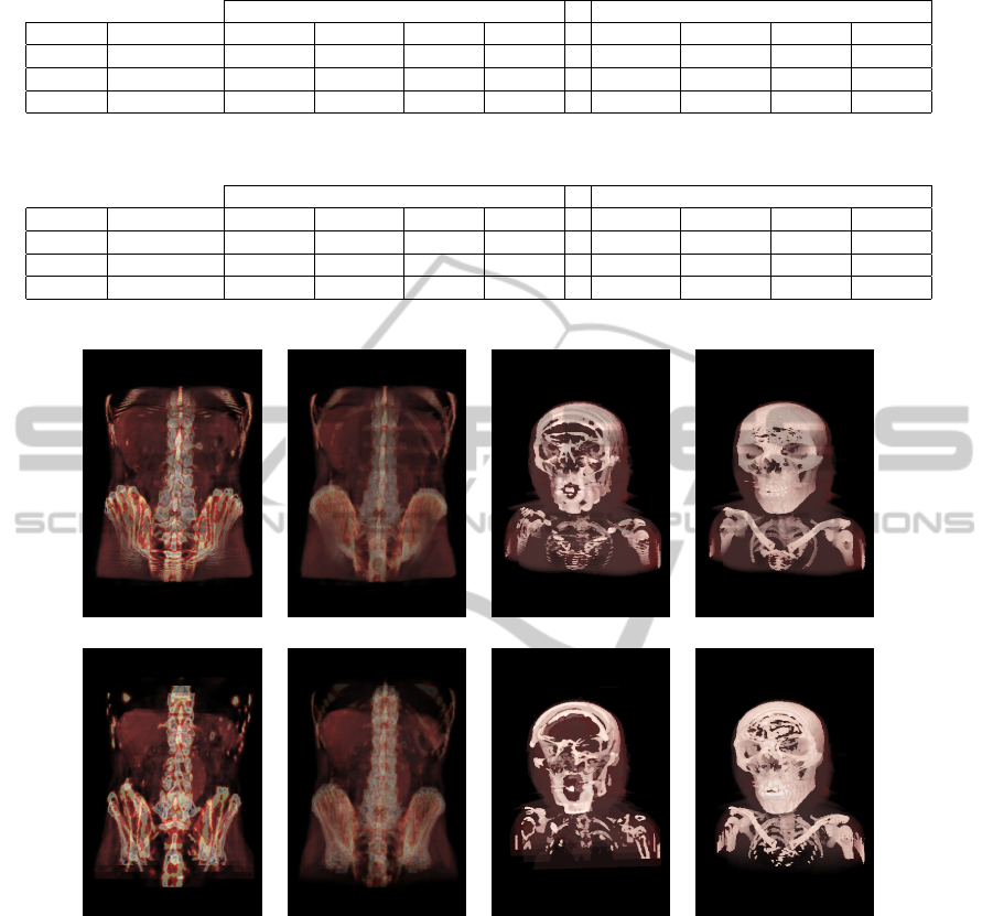
Table 1: Timing for rendering the cthuman model with different devices, image resolutions and number of steps or slices.
Ray Casting Our approach
Device Resolution 10 20 40 80 10 20 40 80
iPad2 480 × 320 23.5 fps 12.1 fps 6.4 fps 3.4 fps 40.1 fps 21.7 fps 11 fps 5.5 fps
iPad2 1024 × 768 5.2 fps 2.8 fps 1.4 fps 1.4 fps 10.3 fps 5 fps 2.4 fps 1.3 fps
iPod 480 × 320 3.2 fps 1.9 fps 1.6 fps 1 fps 6.6 fps 3.2 fps 1.5 fps 1.4 fps
Table 2: Timing for rendering the aorta model with different devices, image resolutions and number of steps or slices.
Ray Casting Our approach
Device Resolution 10 20 40 80 10 20 40 80
iPad2 480 × 320 23.2 fps 12.3 fps 6.5 fps 3.2 fps 45.4 fps 22.2 fps 11 fps 5.4 fps
iPad2 1024 × 768 5.1 fps 2.8 fps 1.5 fps 1.4 fps 10.3 fps 4.8 fps 2.4 fps 1.2 fps
iPod 480 × 320 3.1 fps 1.7 fps 1.6 fps 1.2 fps 6.6 fps 3.2 fps 1.5 fps 1.5 fps
20 steps. 80 steps. 20 steps. 80 steps.
20 slices. 80 slices. 20 slices. 80 slices.
Figure 4: Images from the aorta and cthead models with different number of steps/slices. Top: raycasting approach. Bottom:
our texture slicing approach.
Tables 1 and 2, our texture-slicing approach nearly
doubles the performance obtained by the ray casting
technique. These results suggest that it is preferable
to compute a larger amount of short fragments rather
than a few of them with a more complex behaviour.
We believe that, as the number of processing cores
in mobile GPUs increases, the performance gain of
our technique when compared to the ray-based solu-
tion will also increase, allowing a truly interactive so-
lution to become a reality in this kind of devices.
However, the ray-based technique provides a bet-
ter rendering quality. Figure 4 compares both ap-
proaches for an increasing number of steps/slices. We
notice that the number of slices must be greater than
the number of steps to achieve similar results, due to
the fact that the slices are defined over the bounding
box and some of them can be out of the model.
We have also observed that mobile GPUs are,
in general, less intuitive and more unpredictable in
their performance that their desktop counterparts. It
is paramount to avoid branching in shader programs
for a mobile GPU. Although theoretically branching
is fully supported, including one single if-else clause
can slow down the performance up to 20 fps.
VOLUME RENDERING STRATEGIES ON MOBILE DEVICES
451

Finally, we want to point out another consider-
ation related to the mobile GPU architectures used
in our experiments. PowerVR graphics processors
heavily rely on a method called Tile Based Deferred
Rendering (TBDR) (Power VR, 2011) to achieve
good rendering performance while keeping low en-
ergy consumption. TBDR allows to perform hidden
surface removal before fragments are processed thus
avoiding unnecessarily computations. Unfortunately,
this hardware optimization is not well suited for vol-
ume rendering. The texture slicing technique requires
blending, which forces to process all fragments. In
our experiments, turning off blending boosted the per-
formance to 60 fps regardless of the number of slices
rendered. The raycasting technique does not bene-
fit from this technique because there is no fragments
overlap so no computation can be avoided.
6 CONCLUSIONS
We have developed a novel volume rendering algo-
rithm perfectly suited to modern GPU-enabled mobile
devices. This proposal has addressed the limitations
of these devices, mainly the lack of 3D texture sup-
port and the limited complexity that can be imbued to
shaders. Our method has been tested under different
devices and scenarios. We have also compared our
results with the volume ray casting method. In gen-
eral, our experiments show that the ray-based method
provides a slightly higher quality image, whereas our
texture slicing method doubles the frame rate.
Our work has shown that mobile devices consti-
tutes a valid platform to achieve interactive volume
visualization, despite the fact that the rendering ca-
pabilities are reduced in comparison to desktop solu-
tions, due to their inherent autonomy limitations.
As future work, our current research is focused on
the improvement of the rendering performance and
quality based on a continuous search of new tech-
niques well suited to this kind of devices. We also
plan to improve the visual appearance by including
complex illumination in our models.
In addition, we plan to use our experience and this
technology in university teaching, for instance in sub-
jects like human anatomy, diagnosis, etc. We believe
that interactive visualization of medical data in hand-
held devices can be a worthy pedagogic instrument.
ACKNOWLEDGEMENTS
This work has been partially supported by the
Ministerio de Ciencia e Innovaci
´
on and the Euro-
pean Union (via ERDF funds) through the research
project TIN2011-25259 and by the University of Ja
´
en
through the projects PID441012 and UJA2010/13/08
sponsored by Caja Rural de Ja
´
en.
REFERENCES
Congote, J., Segura, A., Kabongo, L., Moreno, A., Posada,
J., and Ruiz, O. (2011). Interactive visualization of
volumetric data with webgl in real-time. In Proceed-
ings of the Web3D ’11, pages 137–146. ACM.
Hadwiger, M., Ljung, P., Salama, C. R., and Ropinski, T.
(2009). Advanced illumination techniques for gpu-
based volume raycasting. In ACM SIGGRAPH 2009
Courses, pages 2:1–2:166. ACM.
Ikits, M., Kniss, J., Lefohn, A., and Hansen, C. (2004).
GPU Gems II, chapter Volume Rendering Techniques,
pages 667 – 692. Addison Wesley.
ImageVis3D (2011). Imagevis3d: A real-time volume ren-
dering tool for large data. scientific computing and
imaging institute (sci).
Jeong, S. and Kaufman, A. E. (2007). Interactive wire-
less virtual colonoscopy. The Visual Computer,
23(8):545–557.
Khronos Group (2009). The OpenGL ES Shading Lan-
guage, 1.00 edition.
Lamberti, F. and Sanna, A. (2005). A solution for dis-
playing medical data models on mobile devices. In
SEPADS’05, pages 1–7, Stevens Point, Wisconsin,
USA. (WSEAS).
Levoy, M. (1988). Display of surfaces from volume data.
Computer Graphics and Applications, IEEE, 8(3):29
–37.
Moser, M. and Weiskopf, D. (2008). Interactive Volume
Rendering on Mobile Devices. In Workshop on Vi-
sion, Modelling, and Visualization VMV ’08, pages
217–226.
Power VR (2009). PowerVR SGX OpenGL ES 2.0 appli-
cation development recommendations.
Power VR (2011). PowerVR Series5 Graphics SGX archi-
tecture guide for developers.
Rezk-Salama, C., Engel, K., Bauer, M., Greiner, G.,
and Ertl, T. (2000). Interactive volume on stan-
dard pc graphics hardware using multi-textures and
multi-stage rasterization. In Proceedings of the ACM
SIGGRAPH/EUROGRAPHICS workshop on Graph-
ics hardware, HWWS ’00, pages 109–118. ACM.
Van Gelder, A. and Kim, K. (1996). Direct volume ren-
dering with shading via three-dimensional textures. In
Proceedings of the 1996 symposium on Volume visual-
ization, VVS ’96, pages 23–ff., Piscataway, NJ, USA.
IEEE Press.
Weiskopf, D. (2007). GPU-based interactive visualization
techniques. Mathematics and visualization. Springer.
Zhou, H., Qu, H., Wu, Y., and yuen Chan, M. (2006). Vol-
ume visualization on mobile devices. In 14th Pacific
Conference on Computer Graphics and Applications,
pages 76–84.
GRAPP 2012 - International Conference on Computer Graphics Theory and Applications
452
