
Object Recognition based on a Simplified PCNN
Yuli Chen
1,2
, Yide Ma
1
, Dong Hwan Kim
2
and Sung-Kee Park
2
1
School of Information Science and Engineering, Lanzhou University, Lanzhou, Gansu, China
2
Center for Bionics, Biomedical Research Institute, Korea Institute of Science and Technology, Seoul, Korea
Keywords: Simplified Pulse Coupled Neural Network (SPCNN), Image Segmentation, Object Recognition, Region-
based Matching.
Abstract: The aim of the paper is to propose a region-based object recognition method to identify objects from
complex real-world scenes. The proposed method firstly performs a colour image segmentation by a
simplified pulse coupled neural network (SPCNN) model, and the parameters of the SPCNN are
automatically set by our previously proposed parameter setting method. Subsequently, the proposed method
performs a region-based matching between a model object image and a test image. A large number of object
recognition experiments have proved that the proposed method is robust against the variations in translation,
rotation, scale and illumination, even under partial occlusion and highly clutter backgrounds. Also it shows
a good performance in identifying less-textured objects, which significantly outperforms most feature-based
methods.
1 INTRODUCTION
To identify a given object from complex background
in an image or video sequence is an important
branch of the study of object recognition (Ullman et
al., 2001). In real-world scenes, objects may pose
randomly under clutter and partial occlusion in
illumination-changing environment. So an object in
clutter backgrounds may encounter complex
variations in viewpoints, translation, scale, rotation,
and illumination, even under partial occlusion. Thus,
the capability of identifying an object from complex
varying viewing conditions is a significant aspect of
a promising object recognition method.
There have been a large number of works aiming
at endowing computers with the ability to recognize
objects from the real-world scenes. Nowadays, the
feature-based methods, such as Lowe’s scale
invariant feature transform (SIFT) (Lowe, 2004) and
its extension methods (Abdel-Hakim and Farag,
2006; Bay et al., 2008; Bosch, et al., 2008;
Burghouts and Geusebroek, 2009; Ke and
Sukthankar, 2004; Mikolajczyk and Schmid, 2005;
van de Sande et al. 2010; Weijer et al., 2006), have
become become active and dominant methods of
object recognition because of their high accuracy
and fast speed (Mikolajczyk and Schmid, 2005; van
de Sande et al., 2010).
However, the performance of the above feature-
based methods has two critical limitations. One
limitation is that the feature-based methods would
inevitably include background information into local
invariant feature descriptors when keypoints locate
near object boundaries (Stein and Hebert, 2005).
This has been a bottleneck when objects are
identified from heavy clutter environments or
objects that occupy only a small part of the images
(Stein and Hebert, 2005). The other limitation is that
when the feature-based methods are used to identify
less-textured objects (such as doorknob, sofa, TV,
fridge), the number of repeating keypoints that are
correctly matched between model object and test
image is usually very low, and the corresponding
descriptors are usually not discriminative either.
In order to overcome the above limitations, we
develop an region-based object recognition method
based on colour segmentation performed by a
simplified pulse couple neural networks (SPCNN)
model (Chen et al., 2011; Johnson, 1994; Johnson
and Padgett, 1999) whose parameters could be
automatically set by our previously proposed
method (Chen et al., 2011).
we conduct a number of experiments to show the
robustness of the proposed object recognition
method in resisting the variances in translation,
rotation, scale, and illumination (even under partial
occlusion and clutter environments). Moreover, in
223
Chen Y., Ma Y., Kim D. and Park S..
Object Recognition based on a Simplified PCNN.
DOI: 10.5220/0004013102230229
In Proceedings of the 9th International Conference on Informatics in Control, Automation and Robotics (ICINCO-2012), pages 223-229
ISBN: 978-989-8565-22-8
Copyright
c
2012 SCITEPRESS (Science and Technology Publications, Lda.)

order to verify the validity of the proposed method,
we compare it with the state-of-the-art method.
The following part of this paper is organized as
follows. Section 2 simply describes the SPCNN
model with automatic parameters. Section 3
elaborates the proposed object recognition method
with an illustrated example. Section 4 demonstrates
more experimental results. And the last section gives
a conclusion.
2 SIMPLIFIED PCNN WITH
AUTOMATIC PARAMETERS
Pulse coupled neural network (PCNN) was derived
by Johnson et al. (Johnson, 1994; Johnson and
Padgett, 1999) from Echorn’s cortical model which
was developed on the basis of synchronous
dynamics of neuronal activity in cat visual cortex
(Eckhorn et al. 1990). In order to achieve lower
computational complexity, we employ a simplified
pulse coupled neural network (SPCNN) with
parameters automatically set by the automatic
parameter setting method proposed in our previous
paper (refer to the equations (33), (40), (41), (48),
and (49) in Chen et al., 2011). The SPCNN model
was derived from SCM model (Zhan et al., 2009)
and can be described as:
[] [ 1] (1 [ 1])
f
ij ij ij L ijkl kl
kl
Un e Un S V WYn
α
β
−
=−++ −
∑
(1)
1[][1]
[]
0
ij ij
ij
if U n E n
Yn
else
>−
⎧
=
⎨
⎩
(2)
[] [ 1] []
e
ij ij E ij
E
neEn VYn
α
−
=−+
(3)
where
0.5 1 0.5
101
0.5 1 0.5
ijkl
W
⎡⎤
⎢⎥
=
⎢⎥
⎢⎥
⎣⎦
.
(4)
In this model, there are two inputs for the neuron
ij
N
in position (, )ij: input stimulus
ij
S which is the
image pixel intensity, and a simplified linking input
which is the sum of the eight neighbouring neuron
outputs
[1]
kl
Yn− linked by a constant synaptic
weight
ijkl
W . Moreover, the amplitude of the
simplified linking input is denoted by
L
V . These two
inputs are modulated by a linking strength
β
to
yield an internal activity
[]
ij
Un. The internal activity
also records the previous neuron state by an
exponential decay factor
f
e
α
−
. The neuron
ij
N
outputs a pulse in iteration
n ( [] 1
ij
Yn= ) only when
the current internal activity
[]
ij
Un surpasses the last
dynamic threshold
[1]
ij
En− . Subsequently, if neuron
ij
N
fires, the dynamic threshold will increase by
amplitude
E
V
; otherwise, the dynamic threshold will
decay by a factor
e
e
α
−
(Lindblad and Kinser, 2005).
3 PROPOSED OBJECT
RECOGNITION METHOD
PCNN has broad applications in image processing
(Lindblad and Kinser, 2005; Ma et al., 2010),
hereinto, object detection is one of the most potential
applications (Gu, 2008; Kinser, 1996; Ranganath
and Kuntimad, 1999; Yu and Zhang, 2004). Object
detection by PCNN is usually implemented by
generating features which result from encoding the
spatial distributions of a 2D image into a unique
temporal sequence (Johnson, 1994; Gu, 2008; Zhan
et al., 2009). This would result in the loss of image
spatial information that may facilitate the object
detection.
In this paper, we propose an object recognition
method named RBOR-SPCNN (region-based object
recognition with SPCNN), which detects a desired
object from a complex real-world environment. The
proposed method makes use of both spatial and
temporal information. Specifically, the proposed
method employs a specific colour transformation
before using the SPCNN with automatic parameters
(Chen et al., 2011) to segment the colour image into
several syn-firing areas, and finally employs a
region-based matching to output recognition result.
3.1 Colour Space Transformation
In order to resist light intensity change and light
intensity shift that are caused respectively by a
constant gain and an equal offset in all channels, we
carry out a colour space transformation on both
object model image and test image. The colour space
transformation integrates normalized rgb colour
space (scale-invariant) in (5) with opponent colour
space (shift-invariant) in (6) (van de Sande et al.,
2010). Thus, we call the resulting image an “rgb-
opponent” colour image.
,,
RGB
rgb
R
GB RGB RGB
⎛⎞
===
⎜⎟
++ ++ ++
⎝⎠
(5)
ICINCO2012-9thInternationalConferenceonInformaticsinControl,AutomationandRobotics
224
12 3
2
,,
26 3
rg rg b rgb
OO o
−+− ++
⎛⎞
== =
⎜⎟
⎝⎠
(6)
Since all the values in the
3
o channel in (6) are equal
to constant
1
3
, we replace the
3
o
intensity channel
by the normalized gray image and note it as
3
O
channel:
min
3
max min
Ig Ig
O
Ig Ig
−
=
−
(7)
where
Ig
denotes the original gray image.
Due to the subtraction, the
1
O and
2
O channels
may contain some negative values which do not
respond to the SPCNN process. Thus, we
supplement
4
O and
5
O channels by reversing the
1
O
and
2
O
channels as follows:
41
OO=−
(8)
52
OO=− .
(9)
3.2 Colour Segmentation by SPCNN
As for a specific object model, the SPCNN
parameters (Chen et al., 2011) could be estimated
according to the normalized gray object model
image
3
O
.
After the proper SPCNN parameters are
estimated, the SPCNN model with these parameters
could be applied to each of the transformed channels
1
O ,
2
O ,
3
O ,
4
O , and
5
O for object model and test
image, respectively.
In order to guarantee the physical meaning of
image segmentation, we assume that once a pixel in
a channel fires twice, it will be prevented from firing
again (Chen et al., 2011). And we record the second
firing times of the pixels in each channel into a
firing-order matrix. The matrix has the same size as
the image channel.
Thus, we obtain five firing-order matrices
corresponding to the five channels
1
O
,
2
O
,
3
O
,
4
O
,
and
5
O for object model and test image,
respectively:
12345
[;;;;]
mmmmm
CCCCC
(10)
12345
[; ; ; ; ]
ttttt
CCCCC.
(11)
Subsequently, we could gather the pixels firing
synchronously throughout all the five channels as an
image segment called “syn-firing area”. Thus, an
image could be segmented into several “syn-firing
areas”. Specifically, we construct a firing-order
vector for each pixel. For example, the firing-order
vector of the pixel at position
(, )ij
consists of five
elements extracted from the five firing-order
matrices at the same position
(, )ij as follows:
(, ) 1(, ) 2(, ) 3(, ) 4(, ) 5(, )
[]
mmmmmm
ij ij ij ij ij ij
vccccc=
(12)
(, ) 1(, ) 2(, ) 3(, ) 4(, ) 5(, )
[]
tttttt
ij ij ij ij ij ij
vccccc= .
(13)
Thus, a syn-firing area can be formed by grouping
the pixels with the same firing-order vector. In this
manner, the object model and the test images could
be segmented into several syn-firing areas according
to the different firing-order vectors. An example of a
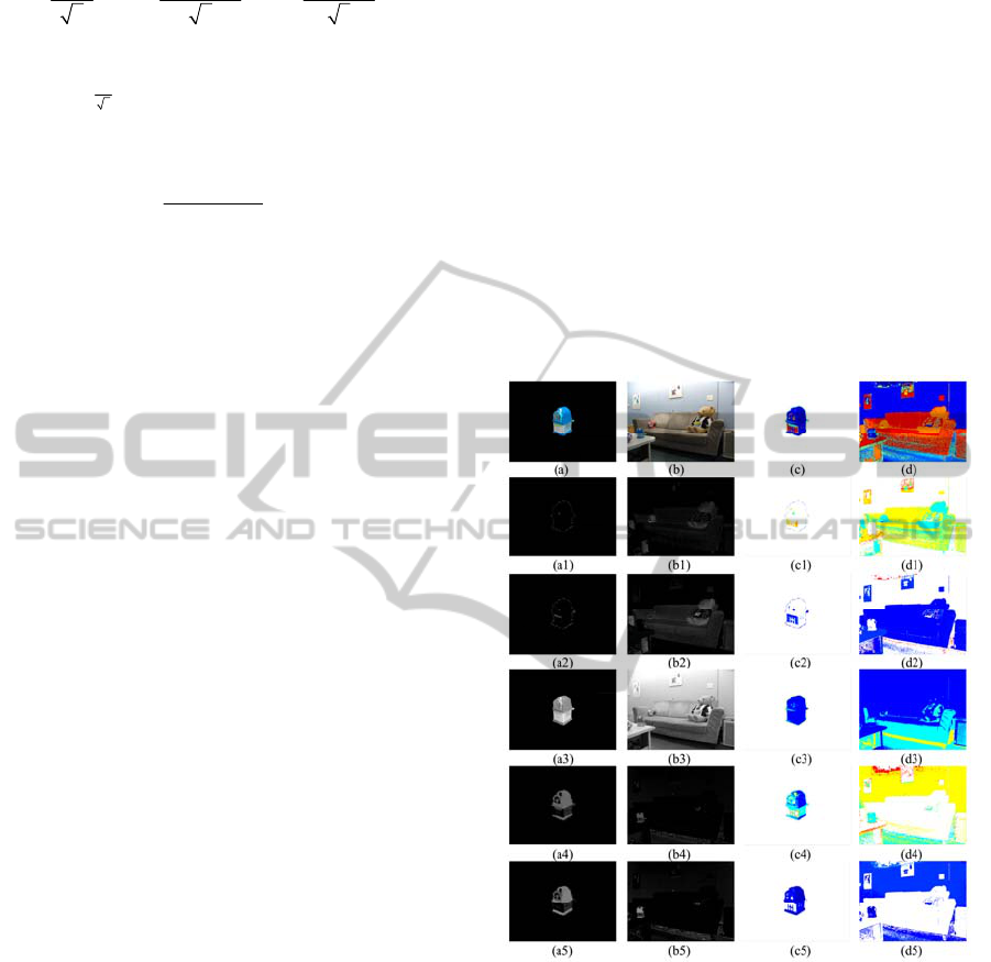
sharpener is shown in Fig. 1.
Figure 1: The
1
O
,
2
O
,
3
O
,
4
O
, and
5
O
transformed
channels of a sharpener image (a) and its test image (b) are
shown in (a1) - (a5) and (b1) - (b5), respectively. And the
corresponding SPCNN firing-order matrices of the five
channels are shown in (c1)-(c5) and (d1)-(d5) in Pseudo-
colours. And the image segmentation results represented
by several syn-firing areas depicted with different Pseudo-
colours are shown in (c) and (d).
3.3 Matching Syn-Firing Areas
We suggest a hypothesis that the same object
possesses the same SPCNN firing-order vectors no
matter how background varies and how object poses.
Based on this assumption, a specific object
ObjectRecognitionbasedonaSimplifiedPCNN
225

model could be identified from a test image of
complex real-word scenes, by means of extracting
the syn-firing areas with the same firing-order
vectors as the syn-firing areas in the object model.
And we define these pairs of syn-firing areas
between the object model and test image as pairs of
matching syn-firing areas. Thus, the test matching
syn-firing areas are the potential regions to contain
the desired object in the test image.
3.4 Region Blobs
The matching syn-firing areas in test image often
disperse and usually include both object and
background pixels. In order to separate the
background pixels and the object pixels, it is
necessary to divide the matching syn-firing areas
into smaller region blobs which are expected to
contain either part of object pixels or part of
background pixels.
In order to speed up the experiments, we remain
only the pairs of matching syn-firing areas whose
model syn-firing area component is larger than 1/50
of the total area of the object model and further split
them into smaller region blobs.
In the process of region splitting, we
successively apply a morphological closing (with a
disk-shaped structuring element of 3-pixel radius)
and an 8-connected components labelling to each
pair of matching syn-firing areas. And the resulting
connected components are labelled as separated
region blobs of the pair of matching syn-firing area.
Since there may still exist some region blobs that
are too small to be meaningful, we only remain the
region blobs with more than 100 pixels (image size:
640*480) in our experiments.
For each of the remained region blobs, we
calculate the region properties, such as ‘area’, ‘major
axis length’, ‘minor axis length’, ‘weighted centroid’
and ‘eccentricity’ (refer to “regionprops” in Matlab).
3.5 Removal of Test Region Blobs with
Irrational Size
Since there may exist many background region blobs
in test image, we may easily remove the obvious
ones by comparing their rough sizes with that of the
object model.
In our experiments, we firstly remove the very
large test region blobs whose area is larger than
argle
τ
times of the test image area (if any), since they
are probably generated by the broad background
test blob test image
argle
AA
τ
>×
.
(14)
Secondly, we remove the test region blobs that
distribute loosely in a large space. That is to remove
the test blobs that are larger than
loose
τ
times of the
coarse distribution area of the object model:
test blob test blob model model
major axis minor axis major axis minor axis
()
loose
LL LL
τ
×>× ×
.
(15)
Besides, since the very long test region blobs are
usually outliers, we could remove the test blobs
whose major axis lengths are larger than
long
τ
times
of the maximum major axis length of the model
region blobs in the pair of matching syn-firing areas:
test blob matching model blobs
major axis major axis
max( )
long
LL
τ
>×
.
(16)
It is noted that the above weight constants are
application-dependent, and we employ
arg
=0.25
le
τ
,
2
loose
τ
=
, and 3
long
τ
= in our experiments based on a
number of experiments.
3.6 Cluster Formation
After the above removal of obvious outlier test
region blobs, the test image has been fragmented and
has many large or small gaps among the object and
background region blobs. Since the desired object
can only occupy a cluster of nearby test region blobs,
we could group the remained nearby test region
blobs into several clusters under a certain radius
distance constraint which is adjustable according to
a specific object model.
Inspired by the cluster seeking method proposed
by Ranganath and Kuntimad (Ranganath and
Kuntimad, 1999), we form clusters as follows:
Step-1: Sort all the test region blobs in a list in
descending order of areas.
Step-2: Mark the test region blob that has the
largest area as the root region blob.
Step-3: Calculate the distances of intensity-
weighted centroids between each test region
blob and the root region blob.
Step-4: Form a cluster by grouping together the
adjacent test region blobs surrounding the
root region blob, under the constraint of a
certain specific cluster radius threshold.
Step-5: Set the area of the root region blob to be
“0” in the list to make sure that this root
region blob cannot become root region blob
again in the following iterations.
Step-6: Repeat Step-1 to Step-5 until the areas of
all the region blobs are set to “0” in the list.
In order to make sure that the cluster radius
threshold is adjustable for different object models,
ICINCO2012-9thInternationalConferenceonInformaticsinControl,AutomationandRobotics
226
the cluster radius threshold could be set as follows:
() ()
thr m m
dmeand stdd
μ
=+×
(17)
where
m
d denotes the distances between the
intensity-weighted centroids of each pair of model
region blobs; and
0.5
μ
= is empirically set based on
plenty of experiments.
3.7 Cluster Refinement
Since some of the obtained clusters are outliers, we
perform a cluster refinement process as follows:
(A) Eliminate the repetitive clusters by retaining
only one of them.
(B) Delete the clusters with areas less than
low
τ
times or larger than
high
τ
times of the total area of the
model region blobs.
cluster model region blobs
low
AA
τ
<×
(18)
cluster model region blobs
high
AA
τ
>× .
(19)
(C) Lastly, remove the clusters with the
eccentricity larger than
eccentr
τ
times of the
eccentricity of the object model, if any.
cluster model
eccentr
EE
τ
>×.
(20)
In the above equations, the weigh constants are
empirically set as
=0.1
low
τ
, =3
high
τ
, and
=7
eccentr
τ
based on a number of experiments.
3.8 Cluster Matching and Object
Recognition Results
After obtaining the above clusters, the next step is to
pick out the cluster which is of the highest
probability to contain the desired object and output it
as the final object recognition result.
In our study, a Bhattacharyya distance of colour
histograms is employed to measure the distance
between each test cluster image and the model
image that is filtered by the model region blobs
()
1
2
1
( , ) 1 () ()
N
ii
model cluster model cluster
n
Dh h h nh n
=
=−
∑
(21)
where
h denotes a colour histogram; n denotes the
n th element of the histogram and i denotes the i th
cluster in the test image.
The histogram is constructed by
12 3
OO O
N
NN N=+ bins (
1
O
N
,
2
O
N
and
3
O
N
are the
bins in
1
O ,
2
O and
3
O channels, respectively). In
our experiments, the histogram dimension is
12 3
20 20 30 430
OO O
NNN N=+=×+=.
(22)
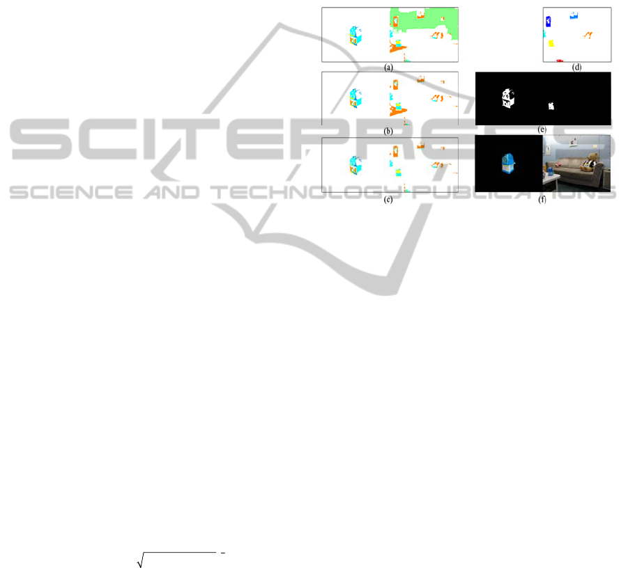
As a result, the test cluster with the minimal
Bhattacharyya distance of colour histograms is
outputted as the final object recognition result shown
as in the right side of Fig. 2 (e). And the compared
result performed by the state-of-the-art
OpponentSIFT (Burghouts and Geusebroek, 2009;
van de Sande et al., 2010) is shown in Fig. 2 (f)
where no matching point is found.
Figure 2: Removal of test region blobs with irrational sizes
and object recognition result. (a) shows all the region
blobs in the pairs of matching syn-firing areas depicted
with different pseudo-colours. The right side of (b) shows
the remained region blobs after a test region blob with area
larger than 1/4 of the test image is discarded; and the right
side of (c) shows the remained region blobs after the long
test region blobs and the large but loose ones are discarded.
(d) shows that only 7 clusters are left after cluster
refinement in test image. (e) shows the object recognition
result by the proposed method. For comparison, (f) shows
the object recognition result performed by the state-of-the-
art OpponentSIFT, where no matching point is found.
4 MORE EXPERIMENTS
In order to examine the general validity of the
proposed RBOR-SPCNN method, we apply it to a
wide range of diverse objects under various
backgrounds. Each object model corresponds to
several test images. As an example, the experiments
of a sharpener are shown in Fig. 3. In the column (b)
of Fig. 3, the sharpeners in the test images are
casually placed in highly clutter environments,
suffering variations in viewpoints, translation,
rotation, scaling, even occlusion.
Moreover, experiments on several other daily
necessities are shown in Fig. 4 as examples. Various
object models are shown in column Fig. 4 (a); some
are less-textured objects, such as cap, chair, and bag.
And the test images with complex real-world
ObjectRecognitionbasedonaSimplifiedPCNN
227
environments are shown in column (b). In each test
image, the desired object is randomly rotated and
scaled. Besides, the tooth past in test image (b2) and
the bag in test image (b7) even suffer partial
occlusion and illumination change.
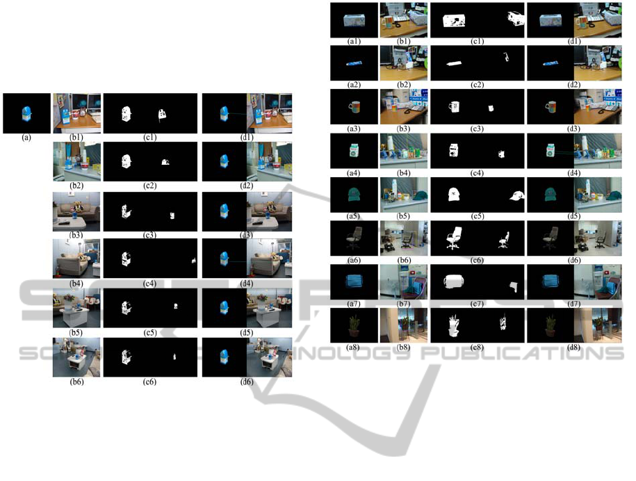
Figure 3: Object recognition results of a sharpener in
different poses and various clutter backgrounds. Object
model is shown in (a). Six test images with complex
backgrounds are shown in column (b). The final object
recognition results obtained by the proposed method are
shown in column (c). The compared results performed by
OpponentSIFT are shown in column (d) where no
matching points for most cases (expect one matching point
appearing in (d1) and (d4), respectively).
Obviously, in both Fig. 3 and Fig. 4, the object
recognition results obtained by the proposed method
(shown as in column (c)) significantly outperform
the compared ones processed by the state-of-the-art
OpponentSIFT (shown as in column (d)) (Burghouts
and Geusebroek, 2009; van de Sande et al., 2010). It
could be seen that the proposed method is not only
capable of detecting occluded objects, such as the
sharpener in Fig. 3 (b5), the tooth paste in Fig. 4
(b2) and the bag in Fig. 4 (b7); but also capable of
detecting less-textured objects, such as the cap, bag,
and chair in Fig. 4 (b5)-(b7), respectively. In
contrast, the OpponentSIFT fails to find any
matching points in such cases.
Figure 4: Object recognition results of diverse objects
under various backgrounds. Column (a) is object models.
Column (b) is test images. All the desired objects in test
images are casually placed in highly clutter environments.
The variations of objects include variations in rotation,
sale and occlusion. The final object recognition results
obtained by the proposed method are shown in column (c).
The compared results performed by OpponentSIFT are
shown in column (d) where no matching point is found in
most cases (expect two matching points in (d4)).
5 CONCLUSIONS
In this paper, we presented a region-based object
recognition method (i.e., RBOR-SPCNN) to identify
specific objects from complex real-world
environments. The proposed object recognition
method performs region-based matching between
object model and test image based on colour image
segmentation performed by the SPCNN with
automatic parameters (Chen et al., 2011).
The proposed method could overcome the
limitation of the feature-based methods that
inevitably include background information into local
invariant feature descriptors (Stein and Hebert,
2005), and the limitation of the feature-based
methods that is incapable of identifying less-textured
objects. As compared to the state-of-the-art
OpponentSIFT, the proposed method showed
encouraging results in identifying diverse objects
from complex real-world scenes.
ICINCO2012-9thInternationalConferenceonInformaticsinControl,AutomationandRobotics
228

REFERENCES
Abdel-Hakim, A. E. and Farag, A. A. (2006). CSIFT: A
SIFT Descriptor with Color Invariant Characteristics.
IEEE Computer Society Conference on Computer
Vision and Pattern Recognition (CVPR)
. New York,
NY, USA, pp. 1978 - 1983.
Bay, H., Ess, A., Tuytelaars, T. and Van Gool, L. (2008).
Speeded-Up Robust Features (SURF).
Computer
Vision and Image Understanding
, 110(3), 346-359.
Bosch, A., Zisserman, A. and Muñoz, X. (2008). Scene
Classification Using a Hybrid
Generative/Discriminative Approach.
IEEE
Transactions on Pattern Analysis and Machine
Intelligence
, 30(4), 712-727.
Burghouts, G. J. and Geusebroek, J.-M. (2009).
Performance Evaluation of Local Colour Invariants.
Computer Vision and Image Understanding, 113(1),
48-62.
Chen, Y., Park, S.-K., Ma, Y. and Ala, R. (2011). A New
Automatic Parameter Setting Method of a Simplified
PCNN for Image Segmentation.
IEEE Transactions on
Neural Networks
, 22(6), 880-892.
Eckhorn, R., Reitboeck, H. J., Arndt, M. and Dicke, P. W.
(1990). Feature Linking via Synchronization Among
Distributed Assemblies: Simulations of Results from
Cat visual Cortex.
Neural Computation, 2(3), 293 -307.
Gu, X. (2008). Feature Extraction using Unit-linking Pulse
Coupled Neural Network and its Applications.
Neural
Processing Letters
, 27(1), 25-41.
Johnson, J. L. (1994). Pulse-Coupled Neural Nets:
Translation, Rotation, Scale, Distortion, and Intensity
Signal Invariance for Images.
Applied Optics, 33(26),
6239-6253.
Johnson, J. L. and Padgett, M. L. (1999). PCNN Models
and Applications.
IEEE Transactions on Neural
Networks
, 10(3), 480-498.
Ke, Y. and Sukthankar, R. (2004). PCA-SIFT: A More
Distinctive Representation for Local Image
Descriptors,
IEEE Computer Society Conference on
Computer Vision and Pattern Recognition (CVPR)
.
Washington, D.C., USA, pp. 506-513.
Kinser, J. M. (1996). Object Isolation.
Optical Memory &
Neural Networks
, 5(3), 137-145.
Lindblad, T. and Kinser, J. M. (2005).
Image Processing
Using Pulse-Coupled Neural Networks
(2nd ed.). New
York: Springer-Verlag.
Lowe, D. G. (2004). Distinctive Image Features from
Scale-Invariant Keypoints.
International Journal of
Computer Vision
, 60(2), 91-110.
Ma, Y. D., Zhan, K. and Wang, Z. B. (2010).
Applications
of Pulse-Coupled Neural Networks
(1st ed.). Berlin,
Germany: Springer-Verlag.
Mikolajczyk, K. and Schmid, C. (2005). A Performance
Evaluation of Local Descriptors.
IEEE Transactions
on Pattern Analysis and Machine Intelligence
, 27(10),
1615-1630.
Ranganath, H. S. and Kuntimad, G. (1999). Object
Detection Using Pulse Coupled Neural Networks.
IEEE Transactions on Neural Networks, 10(3), 615-
620.
Stein, A. and Hebert, M. (2005). Incorporating
Background Invariance into Feature-based Object
Recognition.
IEEE Workshops on Application of
Computer Vision (WACV/MOTION'05)
, Breckenridge,
CO, pp. 37 - 44.
Ullman, S., Sali, E. and Vidal-Naquet, M. (2001). A
Fragment-based Approach to Object Representation
and Classification. In Arcelli, A., Cordella, L.P. and
Sanniti di Baja, G. (Eds.),
International Workshop on
Visual Form
(pp. 85-100). Berlin: Springer.
van de Sande, K. E. A., Gevers, T. and Snoek, C. G. M.
(2010). Evaluating Color Descriptors for Object and
Scene Recognition.
IEEE Transactions on Pattern
Analysis and Machine Intelligence
, 32(9), 1582-1596.
Weijer, J. v. d., Gevers, T. and Bagdanov, A. D. (2006).
Boosting Color Saliency in Image Feature Detection.
IEEE Transactions on Pattern Analysis and Machine
Intelligence
, 28(1), 150-156.
Yu, B. and Zhang, L. M. (2004). Pulse-coupled neural
networks for contour and motion matchings.
IEEE
Transactions on Neural Networks
, 15(5), 1186-1201.
Zhan, K., Zhang, H. J. and Ma, Y. D. (2009). New Spiking
Cortical Model for Invariant Texture Retrieval and
Image Processing.
IEEE Transactions on Neural
Networks
, 20(12), 1980-1986.
ObjectRecognitionbasedonaSimplifiedPCNN
229
