
Evaluating Behavioral Correctness of a Set of UML Models
Yoshiyuki Shinkawa
Department of Media Informatics, Faculties of Science and Technology, Ryukoku University
1-5 Seta Oe-cho Yokotani, Otsu, Shiga, Japan
Keywords:
UML, Model Correctness, Colored Petri Nets, Model Driven Development.
Abstract:
In model driven software development, the correctness of models is one of the most important issues to con-
struct high quality software in high productivity. Numerous research has been done to verify the correctness
of those models. Conventional research mainly focuses on individual models, or at most the relationships
between two individual models. However, the models must be correct as a whole set. This paper presents
a Color Petri Net (CPN) based formal approach to verifying the behavioral correctness of UML models de-
picted by three different kinds of diagrams, namely state machine, activity, and sequence diagrams. This
approach defines the correctness of a set of models from three different perspectives. The first perspective is
the completeness that assures the syntactical correctness of the set. The second is the consistency that claims
no conflicts between heterogeneous UML models. And the last is the soundness that represents the internal
correctness of each model in the set.
1 INTRODUCTION
In model driven software development using UML,
we need a set of sufficiently refined models expressed
in the form of UML diagrams before starting imple-
mentation phase of a development project. One of
the difficulties in preparing the above set is that we
have to arrange the models represented by the differ-
ent forms of diagrams, since UML provides us with
thirteen kinds of diagrams to create the models from
various viewpoints. Even though this variety of no-
tations increases the expression capability of UML, it
also increases the vagueness of the models, and these
models might conflict with each other, which would
make the UML models incorrect.
The incorrectness of the UML models often
causes various problems in the implementation of the
models, such as malfunctions, inconsistent data, or
infinite loops. Therefore, it seems to be one of the
most critical challenges to detect and resolve the con-
flicts in UML models in order to prepare the correct
set of UML models which can be implemented with-
out problems. However there are no definite criteria
to evaluate whether the above set is correct for imple-
mentation.
Numerous research has been done to evaluate
the correctness of UML models using various for-
malization tools, e.g. logic (Amalio and Polack,
2003) (Lausdahl et al., 2009), Petri nets (Garrido and
Gea, 2002)(Shinkawa, 2006), algebraic specification
(Favre and Clerici, 1999), process algebra (Fischer
et al., 2001), and model checking (Knapp and Wuttke,
2006) (Shinkawa, 2008). The above research mainly
focuses on individual models, or at most the relation-
ships between two individual models. However, for
practical use, the correctness of the whole set of UML
models that will be implemented must be proved to be
correct.
This paper presents a Colored Petri Net (CPN)
based formal approach to evaluating the correctness
of a set of UML models, each of which is expressed
in the form of state machine, activity, or sequence di-
agrams. The reason we choose these three kinds of
UML diagrams is that they are most frequently used
to express the behavior of software, and moreover
they are tightly interrelated.
The paper is organized as follows. In section 2,
we discuss the relationships between the above three
kinds of diagrams in order to define the correctness
of a set of UML models. Section 3 introduces a CPN
based formalization of these models for rigorous eval-
uation of the correctness. Section 4 presents how the
formalized UML models are evaluated from several
viewpoints.
247
Shinkawa Y..
Evaluating Behavioral Correctness of a Set of UML Models.
DOI: 10.5220/0004082202470254
In Proceedings of the 7th International Conference on Software Paradigm Trends (ICSOFT-2012), pages 247-254
ISBN: 978-989-8565-19-8
Copyright
c
2012 SCITEPRESS (Science and Technology Publications, Lda.)

2 CORRECTNESS OF UML
DIAGRAMS
When we develop software through Model DrivenAr-
chitecture (MDA) (Warmer et al., 2003), many kinds
of “models” are created in each phase of development,
e.g., “requirement analysis”, “external design”, “in-
ternal design”, and “implementation” phases. These
models are usually expressed in the form of UML di-
agrams. Since UML 2.x provides us with thirteen dif-
ferent kinds of diagrams, we have to deal with a vari-
ety of model forms in MDA-based development.
Before discussing the correctness of a set of UML
models, we first need to reveal the relationships be-
tween these diagrams.
2.1 The Relationships between UML
Diagrams
Among the above thirteen diagrams, “state machine”,
“activity”, and “sequence” diagrams compose one of
the most important set of UML diagrams to represent
the behavioral aspect of a system, since these dia-
grams respectively depict the behavior of objects in
different ways, that is, as the behavior of individual
objects, as the flow of process performed by these ob-
jects, and as the interactions between these objects. In
order to construct a system appropriately that reflects
a given set of UML models expressed in the form of
these three kinds of diagrams, there must be no con-
flicts not only within each model, but also between
the models.
However, few criteria are defined for evaluating
the conflicts between UML models. Therefore, we
first have to define the “relationships” between UML
models. Supposing we are given a set of UML mod-
els depicted by the above three kinds of diagrams,
which represents the behavioral aspect of a system,
it must include all the objects composing the system.
These objects show the different forms according to
in which diagram they appear. Therefore, the rela-
tionships between arbitrary two models expressed in
the form of different diagrams cannot be simply iden-
tified by comparing them. In order to identify the re-
lationships between the above three kinds of models,
we first reveal how an object acts in each diagram.
In a state machine diagram, a diagram itself repre-
sents an object, and the behavior of an single object is
depicted as state transitions. On the other hand, an ac-
tivity and sequence diagrams usually include multiple
objects which behave independently. In a sequence
diagram, an object occurs as a “lifeline”, while no ex-
plicit object occurs in an activity diagram. An object
occurs in two possible forms in an activity diagram,
that is, as an object flow between activities, or as an
actor of an activity.
As shown above, even though an object is a com-
mon element between these three diagrams, its behav-
ior is differently expressed within them. Therefore,
we need more common measures that exist within all
of them. One of the convenient measures is a method
invocation, since it occurs explicitly within these di-
agrams. In a state machine diagram, it is associated
with a state transition, which is referred to as an “ac-
tion” of the transition. It also occurs in an activity
diagram as an “activity” or “action”, or as a “mes-
sage” exchanged between lifelines in a sequence dia-
gram. By using the method invocation as a common
measure, the behavior of an object in the three differ-
ent diagrams is represented commonly as an order of
method invocations.
In order to define the relationships between these
diagram types using the method invocations, sev-
eral assumptions are taken into account in this pa-
per, which seem acceptable in software development.
Firstly, the state of each object is determined by a set
of values assigned to the instance variables of the ob-
ject. Secondly, the above instance variables can be
updated only by the methods of the object to which
the variables belong. This means all the instance vari-
ables are fully encapsulated. Thirdly, each lifeline,
activity, and action mentioned above is definitely as-
sociated with an object.
These assumptions suggest that each time a mes-
sage is received by a lifeline, or an activity/action is
performed in a sequence or activity diagram respec-
tively, the associated object makes a state transition
in the way as specified in the state machine model for
the object. These state transitions divide each life-
line of a sequence diagram into the zones associated
with the states. On the other hand, there seems to be
no way to divide an activity diagram by the states,
since unlike a sequence diagram, an activity diagram
is not partitioned by each object unless we use “swim
lanes”. Therefore, in order to divide an activity di-
agram into the zones like a sequence diagram, it is
a good practice to reorganize an activity diagram by
aligning activities and actions along the objects that
perform them. In doing so, we can divide an activ-
ity diagram into the zones like a sequence diagram.
Since the state for each zone is taken from a state ma-
chine diagram, we refer to the states in an activity or
sequence diagram as the “injected state”, and the pro-
cess to identify the state as the “state injection”.
Assuming all the activity and sequence diagrams
included in the currently focused set are divided into
such zones, the above three kinds of UML models,
that is, the models depicted by UML state machine,
ICSOFT2012-7thInternationalConferenceonSoftwareParadigmTrends
248

activity, or sequence diagrams, are to have another
common measure “state” to evaluate the correctness.
2.2 Three Perspectives on Correctness
In order to evaluate the correctness of a set of
UML models using the above two measures, namely
“method invocation” and “zone of the state”, some re-
strictions are imposed on the UML models composing
the set to be evaluated.
First of all, any method name that occurs in an
activity or sequence model
1
must occur in the cor-
responding state machine model with the same sig-
nature. Here the corresponding state machine model
means the state machine model that represents the ob-
ject including the method. In addition, each activ-
ity/action in an activity model, and each lifeline in a
sequence model, must be uniquely associated with an
object.
On the contrary, some method names that occur in
a state machine model may not occur in any activity
or sequence models in the set of UML models, since
we assume each state machine model represents all
the possible state transitions by method invocations,
while the object within an activity or sequence model
only show a part of these transitions.
When a set of UML models satisfies the above
conditions, all the activities/actions in the activity dia-
grams, and all the message exchanges in the sequence
models, can be fully related to the state transition
in the corresponding state machine model through
method invocations. This means we can rigorously
evaluate the correctness of the set. We refer to
such a model that satisfies the above conditions as a
“complete” model, and such the property of a set of
UML models as “completeness”.
Assuming a set of UML models is complete, the
behavior of each model can be interrelated through a
series of method invocations. As mentioned above, a
state machine model represents the whole behavior of
the object, while an object in an activity or sequence
model may show a part of the behavior. Therefore, the
behavior of an object in an activity or sequence model
must be a part of the behavior of the corresponding
state machine model. The behavior of an object is de-
fined as a series of method invocations in this paper,
therefore there is another constraint that must be sat-
isfied by a set of UML models.
This constraint requires that any series of method
invocation in an activity or sequence model must oc-
cur in the corresponding state machine model when
1
A model represented in the form of an state machine
diagram is referred to as a state machine model. An activity
and sequence models are interpreted as well.
execute the models. We refer to a set of UML
models that satisfies this constraint as a “consistent”
set, and the property of a set of UML models as
“consistency”.
The above two constraints for the model correct-
ness mainly focus on the mutual integrity between the
models, however few concerns are taken about the in-
ternal correctness within each model. As for this type
of correctness, UML provides us with a few model
components to give the constraints. One is the state
invariant in a sequence diagram, and the other is a
set of the pre- and post-conditions in an activity dia-
gram
2
.
Both constraints require a model to have the des-
ignated state at the specified point. If the set of UML
model is complete and consistent, each activity or se-
quence model can be dividedinto the zones associated
with the injected states, and therefore we can evaluate
the validity of the given state invariants or pre- and
post-conditions. For the validation of state invariants
or pre- and post-conditions against the injected states,
these states must be expressed in the common formal
way. One of the appropriate ways is to express them
in the form of predicate logic formulae which include
the instance variables.
Assuming the predicate logic formula for a pre-
or post-condition, or state invariant is P(~x), and the
injected state of the zone where the P(~x) is located be
Q(
~
x
′
), P(~x) must hold under the condition Q(
~
x
′
), that
is, Q(
~
x
′
) → P(~x) must hold. Here, ~x and
~
x
′
represent
the arguments of the predicates or functions included
in the formulae P and Q, which consist of the tuples of
instant variables. We refer to a set of UML models as
“sound” if all the state invariants, pre-conditions, and
post-conditions in the set satisfy the above constraint,
and such a property of UML models as “soundness”.
The above three perspectives, namely complete-
ness, consistency and soundness assure the correct-
ness of a set of UML models from individual model
level to a whole system level. However, the UML
models within the set are specified by three kinds of
diagrams, and difficult to examine the correctness. In
addition, UML itself is comparably vague for rigor-
ous correctness evaluation. Therefore we need more
formal and common notation for the UML models
in the set. In the next section, we discuss Colored
Petri Nets (CPN) as a common notation and evalua-
tion tool.
2
Local pre- and local post-conditions are also provided
for an action.
EvaluatingBehavioralCorrectnessofaSetofUMLModels
249

3 CPN MODELING FOR UML
Colored Petri Net (CPN) is an extension of a regu-
lar Petri net, which introduces functionality and data
types for more flexible control of the regular Petri net
(Jensen and Kristensen, 2009). CPN is formally de-
fined as a nine-tuple CPN=(P, T, A, Σ, V, C, G, E, I) ,
where
P : a finite set of places.
T : a finite set of transitions.
(a transition represents an event)
A : a finite set of arcs P∩ T = P∩ A = T ∩ A =
/
0.
Σ : a finite set of non-empty color sets.
(a color represents a data type)
V : a finite set of typed variables.
C : a color function P → Σ.
G : a guard function T → expression.
(a guard controls the execution of a transition)
E : an arc expression function A → expression.
I : an initialization function : P → closed expression.
In this section, we briefly introduce how the above
three kinds of UML models are expressed in the form
of CPN.
3.1 Transforming State Machine
Models into CPN
Both the state machine models and CPN models have
the similar structures to finite automata with variable
(Skoldstam et al., 2007). Therefore, state machine
models are transformed into CPN by relatively sim-
ple rules. The structural relationships between these
two models are as follows.
1. Each state in a state machine model corresponds
to a place in a CPN model. The color of the place
is composed of the data types that determine the
state.
2. A state transition corresponds to a transition lo-
cated between two places that reflect the source
and destination states of the state machine
Other complicated control structures, such as a
composite state, or pseudo states like fork/join,
choice/junction, and history, can be transformed into
CPN (Shinkawa, 2011). For example, junction
pseudo state is expressed in the form of CPN as shown
in Figure 1. In addition to the structural transforma-
tion, model semantics must also be transformed. The
semantics of a state machine model can be defined by
the two contrastive viewpoints, namely “static” and
“behavioral”. The former semantics represents “what
each state means”, and expressed in the form of pred-
icate logic formulae as discussed above. On the other
hand, the latter semantics represents “how the model
S1 S2
S3 S4
S5
P1 P2
T1 T2
P
T3 T4 T5
P3 P4 P5
a3 a4 a5
[g3]
[g4]
[g5]
[g3] [g4] [g5]
Figure 1: Junction pseudo state.
makes state transitions”, which is controlled by the
guards on the transition arcs and pseudo states. These
guards can also be expressed in the form of the predi-
cate logic formulae. In CPN, these logic formulae are
expressed as CPN/ML functions with boolean result
values.
3.2 Transforming Activity Models into
CPN
Both an activity model and a CPN model express the
progress of a process, and they have similar structures
(Eshuis and Wieringa, 2003). While a CPN model
is structurally composed of only four graphical el-
ements, an activity model consists of many graphi-
cal elements to express complicated control flows. In
spite of the different appearances, the structure of an
activity model can be transformed into CPN as fol-
lows.
1. Replace each activity and action by a transition
with an output place from it.
2. Replace each initial and final node by a place.
3. Replace a fork node, which split a single flow
of control into parallel flows, by a transition
with multiple output places to initiate the paral-
lel flows. And replace a join node, which merge
parallel flows of control into a single flow, by a
transition with multiple input places.
4. Replace a decision node by a place with multiple
output transitions, each of which has the guard for
conditional branch, and replace merge node by a
place with multiple input transitions.
5. Replace each accept event action, which deals
with an asynchronous event, by a transition with
an input place, and replace each send signal ac-
tion , which generates a message or signal, by a
transition with an output place
3
.
6. Replace an event handler in the same way as the
3
The occurrence of an asynchronous event is controlled
by a token that is marked in the input place.
ICSOFT2012-7thInternationalConferenceonSoftwareParadigmTrends
250

accept event action. While an accept event ac-
tion deals with an asynchronous event that occurs
outside the model, an event handler deals with an
exceptional event that occurs in the model. How-
ever, they can be expressed in the same way in a
CPN model.
7. Replace an iteration expansion region by a tran-
sition with an input place to which the transition
feedbacks the token, replace a parallel expansion
region by the same CPN structure as the fork and
join node, and replace a stream expansion region
by transition with output place.
In addition to the above structural transformation
rules, semantic transformation rules must be defined
as we did for state machine models. The semantics of
an activity model is described as a method associated
with each activity/action along with a guard on each
flow or decision node. These semantic elements can
be transformed into CPN/ML functions in the same
way as state machine models.
3.3 Transforming Sequence Models into
CPN
Unlike a state machine or activity model, the appear-
ance of a sequence model is quite different from that
of a CPN model. However, since the behavior of a se-
quence model is defined as a series of message pass-
ing, which can be interpreted as a series of method
invocations, the model shows the similar behavioral
characteristics to a state machine or activity model.
Therefore, a sequence model can be transformed into
the behaviorally equivalent CPN model in the similar
way to the transformation of a state machine or an ac-
tivity model as mentioned above. The transformation
rules are summarized as follows (Shinkawa, 2011).
1. Replace each receiving event occurrence by a
transition with an output place.
2. Replace an alt, opt, break, and loop combined
fragment by two conflicting transition with appro-
priate guards to control the branch operation.
3. For a critical combined fragment, add a special
place that holds a “lock” token, and draw bi-
directional arcs to the transitions that conflict with
the fragment.
4. Replace a par fragment by a transition with mul-
tiple output places for concurrent operations.
5. Replace a seq fragment in the same way as the par
fragment, then add the arcs to control the required
sequences
4
from the output place of a preceding
transition to the succeeding transition.
In addition to the above structural transformation
rules, the semantic transformation rules are needed.
These rules are based on method invocations and
guards in such combined fragments as alt, opt, and
loop, and can be transformed in the similar way to
activity models.
3.4 Zoning Activity and Sequence
Models
In order to discuss the soundness of activity and se-
quence models, we need to divide the CPN models
transformed from them into zones based on states so
that we can identify the state at any point of the mod-
els. Since the state of each object is updated by a
method invocation of the object, and each method
corresponds to a transition with an output place, the
state is regarded to be expressed as the token value
marked in the output place. Therefore, each output
place of the transition that corresponds to a method
can be classified based on the states. On the other
hand, the state of the transitions can be defined to be
the same as that of the input place, since the state is
updated after the firing of the transitions.
The discussion so far suggests that a transition
with an input place and the connecting arc compose
a smallest unit of a state in a transformed CPN model.
However, there could exist the transitions that do not
correspond to methods, but represent some control
structures such as if - then -else, loop, break, and so
on. These transitions do not affect the state of a sys-
tem, and therefore the states of these transitions, asso-
ciated places, and arcs are taken over from the states
of the preceding units of states.
The transformed CPN models are divided into
zones based on the above concept. The concrete pro-
cedure to define the states is discussed in the next sec-
tion.
4 EVALUATING THE MODEL
CORRECTNESS
The correctness of a set of UML models, which in-
cludes state machine, activity, and sequence models,
has three different perspectives as mentioned in sec-
tion 2.
The first perspective is the completeness of the set.
This perspectivemeans that each method name within
the activity models or sequence models occurs within
4
The required sequences by the seq fragment are slightly
confusing and tricky. The detailed description is found in
(OMG, 2011).
EvaluatingBehavioralCorrectnessofaSetofUMLModels
251

the corresponding state machine model. In the ac-
tivity models, the method invocations are associated
with the activities or actions, while in the sequence
models, they are associated with message passing.
The second perspective is the consistency of the
set, which means the activity and sequence models
behave consistently with the corresponding state ma-
chine models. The behavior of the models is defined
based on the order of method invocations.
The last perspective is the soundness of the set,
which means all the activity and sequence models in
the set satisfy the state based constraints designated
by pre- and post-conditions, or by state invariants.
The states in these models are injected from the cor-
responding state machines.
In this section, we discuss how the above three
perspectives of the correctness are verified in the
transformed CPN models.
4.1 Verification of Model Completeness
When transforming state machine models, activity
models, and sequence models into CPN models, all
the methods are implemented in the form of CPN/ML
functions. Since all the methods that occur in the
activity or sequence models must occur in the corre-
sponding state machines, one of the simplest ways to
preserve the completeness is to transform and com-
pose the CPN models from all the state machine mod-
els before transforming other model types. And in
subsequent transformation for activity and sequence
models, method implementation by CPN/ML is re-
stricted to only referring the functions already defined
in the state machine models. By avoiding to create
new CPN/ML functions in the transformation of ac-
tivity and sequence models, all the method names and
their arguments are controlled by the state machine
models. As a result, the completeness is assured by
CPN/ML compiler.
4.2 Verification of Model Consistency
In order to evaluate the consistency of a set of UML
models, we first need to identify the order or sequence
of method invocations for each object in the mod-
els. For this purpose, we append trace facility to each
transformed CPN model. This facility is composed of
a place to hold the history of method invocations, arcs
to/from all the transitions, and a transition to exam-
ine the above history. In addition, several data types
are introduced as color sets to express the history,
namely “colset Object = int” to distinguish each ob-
ject, “colset Method = int” to distinguish each method
in a object, “colset MethodList = list Method”, and
“colset Trace = product Object * MethodList”.
The history of method invocations is expressed
as a token with the color “Trace”, and is created for
each object. The place to hold the history is labeled
“TraceHolder-m”, where m(= 1, 2,· · · ) represents the
CPN model id, and the place is associated with the
color “Trace”. The arc function of the arc to the
“TraceHolder-m” is defined as follows.
1. For a transition on a single process path that rep-
resents a method, add the method id to “Method-
List” part of the “Trace” token of the object.
2. For a transition to split a single process path into
n parallel process paths, terminate the current
“Trace” token by adding a unique negative inte-
ger at the end of the “MethodList” part. Sub-
sequently, create n new “Trace” tokens for the n
parallel paths, of which “MethodList” part begin
with the above unique negative integer followed
by a path id p (= 1, 2,· · · , n).
3. For a transition on the i-th path of the n paral-
lel paths, use the “Trace” token of which “Mod-
uleList” part has “i” as the second element.
4. For a transition to merge n parallel paths into a
single path, terminate n “Trace” tokens by adding
the same negative integer as the first element at the
end of “ModuleList” part. The succeeding transi-
tions use the same “Trace” token before the most
recent transition to split.
Each CPN model is modified as shown in Figure
2. By the above modification of CPN models, each
CPN model yields a set of “Trace” tokens in its own
“TraceHolder-m”. The consistency evaluation is to
be made between a state machine model and activity
or sequence model, focusing on a particular object.
Since we assume a state machine model is built for
each object, and several activity and sequence models
are built including these objects, the consistency eval-
uation should be made object by object. This evalua-
tion can be made by the guard function of a transition
with two input places, one is the “TraceHolder-m” of
a state machine, and the other is that of an activity or
sequence model. The guard function examines a pair
of “Trace” tokens from the state machine model and
an activity or sequence model. Since each “Trace”
token includes an object id, we can extract the neces-
sary tokens from the “TraceHolder-m” of the activity
or sequence model to evaluate whether they satisfy
the consistency criteria. The detailed evaluation steps
are as follow.
1. Let P and Q be CPN models which are trans-
formed from an activity or sequence model, and
from a state machine model respectively.
ICSOFT2012-7thInternationalConferenceonSoftwareParadigmTrends
252
CPN-post
CPN-pre
a
b
Trace Holder
Figure 2: Trace holder place.
2. Let trace(P) and trace(Q) be a pair of “Trace” to-
kens for the same object, both “ModuleList” part
of which have the same integer as the first ele-
ment.
3. The model P and Q are consistent if the “Mod-
uleList” part of trace(P) includes that of trace(Q)
as a substring.
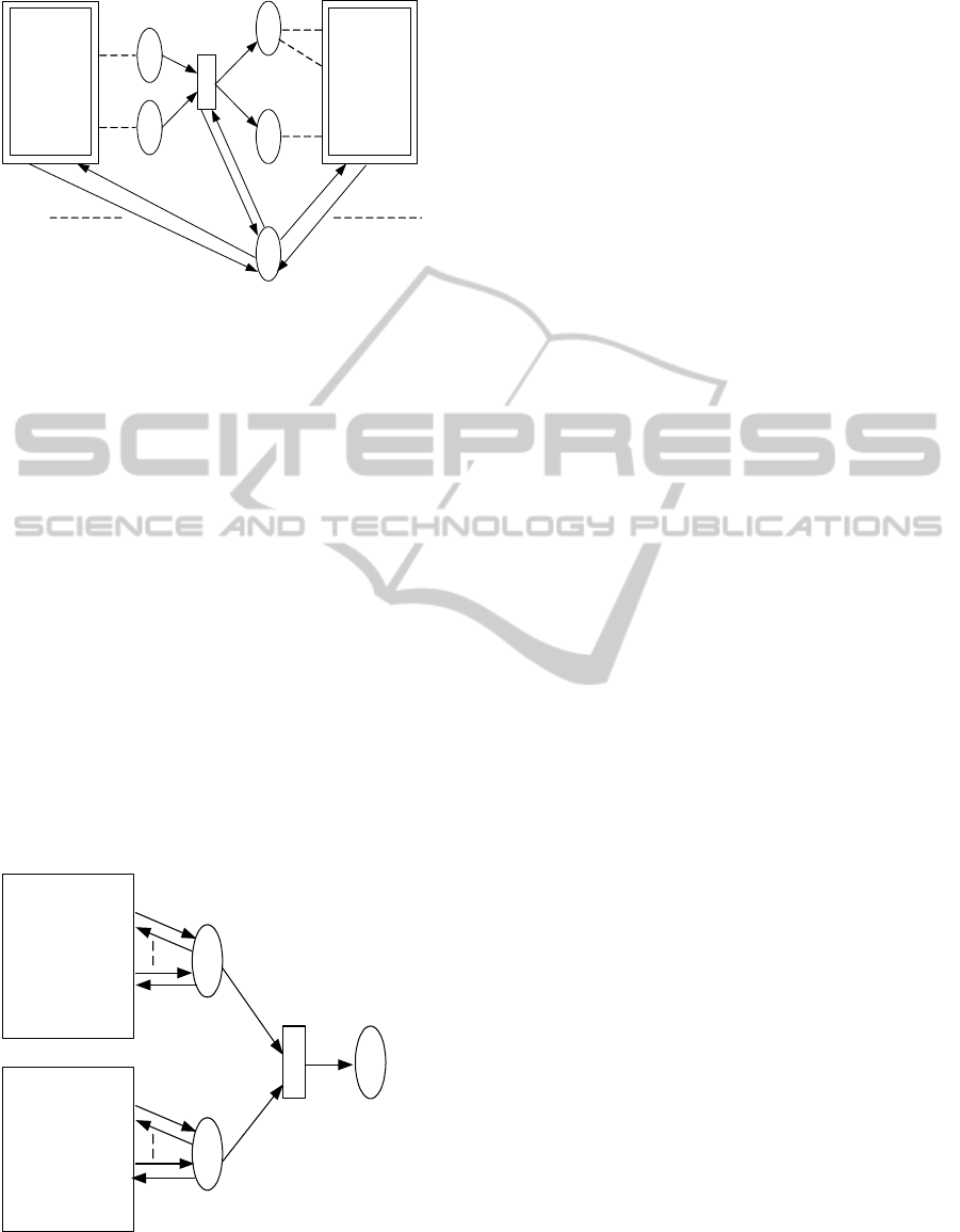
The verification of the consistency between two
CPN models, one is from an activity or sequence
model, and the other is from a state machine model,
is performed as shown in Figure 3. In this figure, the
gurd g of the transition e examines the consistency be-
tween P and Q according to the above algorism. The
guard g returns true if P and Q are NOT consistent.
If the inconsistency is detected, the transition e re-
moves the “Trace” token from the “TraceHolder-m”,
and consequently the succeeding transitions in P and
Q halt. The transition e provides the error message
token to the place “Inconsistent”.
e
P
CPN from an
Activity/
Sequence
Q
CPN from a
State Machine
TraceHolder-m
TraceHolder-n
[g]
Inconsistent
Figure 3: Consistency verification.
4.3 Verification of Model Soundness
For model soundness verification, we need the in-
jected states at the locations where pre- and post-
conditions or state invariants are specified. The in-
jected state at an output place of a transition t is deter-
mined as the state in the corresponding state machine
model, to which there is a state transition associated
with the same method invocation as the above tran-
sition t. However, the same method invocation may
occur at several states in the state machine model.
Therefore we need to find the most adequate corre-
spondence of the method invocation between the state
machine and the activity or sequence models. This
correspondence is identified by examining the same
series of method invocations in both of them.
This examination can be done in the similar way
to the consistency verification. The detailed process
is shown as follows.
1. Let the place in the activity or sequence model
be p, to which the state is to be injected, and the
transition and the associated method be t and m
respectively.
2. Let the places in the corresponding state ma-
chine model be q
1
,q
2
,· · · , q
n
, to which the
transitions
1
,s
2
,· · · , s
n
that represents the method
m supply tokens.
3. Prepare two places c
1
and c
2
for controlling the
state injection, and draw an outgoing arc from t
and s
1
respectively.
4. Prepare a transition e
1
which has a pair of incom-
ing/outgoing arcs from/to the “TraceHolder-m” of
each model, and draw incoming arcs from c
1
and
c
2
.
5. Set the guard g of the transition e
1
in the same
way as the consistency verification.
6. Prepare a transition e
2
which has the same struc-
ture as e
1
, and set the guard functioning as the
negation of g, namely ¬g.
7. Repeat the steps 3 to 6 for s
2
tp s
n
.
The above process could find multiple identical
series of method invocations in the state machine
model. In such case, we cannot identify the state of
the place currently focused on, but can obtain a set
of possible states. Therefore, the verification of the
model soundness should be examined for all the pos-
sible states. The verification for each state is made as
follows.
1. For the place p associated with a state invariant
S, which is expressed in the form of a predicate
logic formula, put a new transition e that refers
to the token of p. The guard g of the transition e
EvaluatingBehavioralCorrectnessofaSetofUMLModels
253

implements the formula “¬(T → S)”, where T is
the injected state of p.
2. For the place q
1
and q
2
associated with a pre- and
post-conditions respectively, put new transition e
1
ande
2
that refer to the token e
1
and e
2
. The guards
g
1
and g
2
of e
1
and e
2
implement “¬(T
1
→ S
1
)”
and “¬(T
2
→ S
2
), where T
1
and T
2
are the injected
states of q
1
and q
2
.
The above CPN structure halts the CPN model
execution if a soundness violation is detected in the
same way as the consistency verification, which is
shown in Figure 3.
5 CONCLUSIONS
A Colored Petri Net (CPN) based evaluation process
for the correctness of a set of UML models is pre-
sented in this paper. While the previous research
mainly focused on the correctness of individual UML
models, or the relationships between two individual
models, this process deals with a set of UML mod-
els described by three different kinds of diagrams,
namely a state machine, activity, and sequence dia-
grams. The correctness of the set is discussed from
three perspectives, that is, completeness, consistency,
and soundness of the set.
The completeness of the set assures no syntactic
conflicts exist within the set, while consistency and
soundness guarantee the semantic correctness of the
set. In order to evaluate the correctness rigorously
using those criteria, all the UML models are trans-
formed into CPN models.
The completeness of the set can be verified by
transforming all the state machine models into CPN
with preparing associated CPM/ML functions before
transforming other types of models. On the other
hand, the consistency and soundness verifications
need additional CPN components to the transformed
CPN models, which examine the order of method in-
vocations and injected states adequately.
The presented process can assure not only the cor-
rectness of each model in the set, but also the correct-
ness of complicated interrelationships between the
models, so that we can provide more accurate soft-
ware specifications.
REFERENCES
Amalio, N. and Polack, F. (2003). Comparison of formal-
isation approaches of uml class constructs in z and
object-z. In 3rd international conference on Formal
specification and development in Z and B, pages 339–
358. Springer-Verlag.
Eshuis, R. and Wieringa, R. (2003). Comparing petri net
and activity diagram variants for workflow modelling:
A quest for reactive petri nets. In Petri Net Technology
for Communication-Based Systems: Advances in Petri
Nets, pages 321–351. Springer.
Favre, L. and Clerici, S. (1999). Integrating uml and alge-
braic specification techniques. In 32nd International
Conference on Technology of Object-Oriented Lan-
guages and Systems, pages 151–162.
Fischer, C., Olderog, E., and Wehrheim, H. (2001). A
csp view on uml-rt structure diagrams. In 4th Inter-
national Conference on Fundamental Approaches to
Software Engineering, pages 91–1–8. Springer-Verla.
Garrido, J. and Gea, M. (2002). A coloured petri net for-
malisation for a uml-based notation applied to coop-
erative system modelling. In the 9th International
Workshop on Interactive Systems. Design, Specifica-
tion, and Verification, pages 16–28. Springer-Verlag.
Jensen, K. and Kristensen, L. (2009). Coloured Petri
Nets: Modeling and Validation of Concurrent Sys-
tems. Springer-Verlag.
Knapp, A. and Wuttke, J. (2006). Model checking of uml
2.0 interactions. In Workshops and Symposia at MoD-
ELS 2006, pages 45–51.
Lausdahl, K., Lintrup, H., and Larsen, P. G. (2009). Con-
necting uml and vdm++ with open tool support. In the
2nd World Congress on Formal Methods, pages 563–
578. Springer-Verlag.
OMG (2011). Unified Modeling Language Superstructure.
http://www.omg.org/spec/UML/2.4.1/Superstructure/
PDF.
Shinkawa, Y. (2006). Inter-model consistency in uml based
on cpn formalism. In 13th Asia Pacific Software En-
gineering Conference, pages 411–418. IEEE.
Shinkawa, Y. (2008). Model checking for uml use cases.
In Software Engineering Research, Management and
Applications 2008, pages 233–246. Springer.
Shinkawa, Y. (2011). Inter-model consistency between uml
state machine and sequence models. In 6th Interna-
tional Conference on Software and Data Technolo-
gies, Vol 2, pages 135–142.
Skoldstam, M., Akesson, K., and Fabian, M. (2007). Mod-
eling of discrete event systems using finite automata
with variables. In 46th IEEE Conference on Decision
and Control, pages 3387–3392. IEEE.
Warmer, A., Bast, J., and Kleppe, W. (2003). MDA Ex-
plained: The Model Driven Architecture?: Practice
and Promise. Addison-Wesley Professional.
ICSOFT2012-7thInternationalConferenceonSoftwareParadigmTrends
254
