
Quality Improvement of Requirements Specification
using Model Checking Technique
Yoshitaka Aoki
1
, Shinpei Ogata
2
, Hirotaka Okuda
1
and Saeko Matsuura
1
1
Graduate School of Engineering and Science, Shibaura Institute of Technology,
307 Fukasaku, Minuma-ku, Saitama-City, Saitama 337-8570, Japan
2
Department of Computing, Shinshu University, 4-17-1 Wakasato, Nagano-shi, Nagano 380-8553 Japan
Keywords: Requirements Analysis, Quality Improvement, Model Checking, Model Driven Development.
Abstract: A key to success of high quality software development is to define valid and feasible requirements
specification. We have proposed a method of model-driven requirements analysis using Unified Modelling
Language (UML). The main feature of our method is to automatically generate a Web user interface
prototype from UML requirements analysis model so that we can confirm validity of input/output data for
each page and page transition on the system by directly operating the prototype. This paper proposes a data
life cycle verification method using a model checking technique UPPAAL. Exhaustive checking improves
the quality of requirements analysis model which are validated by the customers through automatically
generated prototype.
1 INTRODUCTION
Model Driven development (Paulo et al., 2005;
Monteiro et al., 2010; Forward et al., 2010; Rational
Software Modeler) is a promising approach to
develop high quality software products efficiently.
Supporting Tools such as a source code generator
and several domain specific languages have been
proposed (Rational Software Modeler). However, to
obtain high quality source codes, appropriate models
that meet customer's requirements should be well
defined at the requirements analysis phase which is a
start point of the system development. At the
requirements analysis phase, it is difficult to strictly
define requirements analysis models so that they can
be translated into the source codes. This is because
that the user requirements are often ambiguous,
imprecise, insufficient and incomplete. To make the
requirements analysis models precise, the developers
should fully understand user requirements and
define the problems that the customer is trying to
solve as precisely as possible. Moreover, the
requirements specification is the result of analysis so
that it can offer correct and sufficient information to
the following phases to generate the final product
automatically.
We have proposed a method of model-driven
requirements analysis (Ogata and Matsuura, 2008;
Ogata and Matsuura, 2010) using Unified Modelling
Language (UML). The main feature of our method is
to automatically generate a Web user interface
prototype from UML requirements analysis model
so that we can confirm validity of input/output data
for each page and page transition on the system by
directly operating the prototype.
Models are effective in specifying the target
system by the different aspects. However, the
resultant integrated model often has some defects
that are difficult to detect on each individual model
such as omissions on entity data life cycle.
This paper proposes a data life cycle verification
method using a model checking technique.
Exhaustive checking improves the quality of
requirements analysis model which are validated
through automatically generated prototype.
Based on the method and the supporting tool,
this paper discusses validation and verification
process on the requirements specifications. The rest
of the paper is organized as follows. Section 2
explains what is the goal and the requisite quality of
requirements specification. Section 3 explains the
process of our model driven requirements analysis.
Section 4 explains the verification process using
Model Checking technique.
401
Aoki Y., Ogata S., Okuda H. and Matsuura S..
Quality Improvement of Requirements Specification using Model Checking Technique.
DOI: 10.5220/0004156104010406
In Proceedings of the 14th International Conference on Enterprise Information Systems (MDDIS-2012), pages 401-406
ISBN: 978-989-8565-11-2
Copyright
c
2012 SCITEPRESS (Science and Technology Publications, Lda.)
2 THE GOAL AND THE
QUALITY OF REQUIREMENTS
SPECIFICATION
One of the goals that a requirements specification
needs achieving is that the customers can validate
that the specification meets their expectations from
the viewpoint of the actual usage. Namely, they
want to confirm how to use the system to get their
desired service. The other goal is that the developer
can verify the specification so as to confirm the
feasibility of the specification. Namely, it is
important that a requirements specification has no
ambiguity for the developers at the design phase
about the terms and their relations among it, so that
all the sentences can be interpreted by them in
uniquely. All the expected responses of the system at
every effective usage of it need specifying from the
viewpoint of the input/output data. Moreover, it is
required that there is no contradiction in the relation
between behaviour and data on the requirement.
Even if a requirements specification is written in not
natural language, but such diagrams as UML and
screen images, the qualitative problems may still
remain unsolved. This is because these qualitative
problems cannot be checked by using such an
executable integrated model as program codes.
IEEEstd.830 (IEEE Computer Society, 1998) has
been known as a standard of requirements
specification construction. When most developers
specify a requirements specification according to the
standard, it is difficult for them to fully pay attention
to interrelationship between all components in the
documents so as to achieve the goal of a
requirements specification.
As our model-driven requirements analysis
method has argued, models are effective in
specifying the target system by the different aspects.
However, the resultant integrated model often has
some defects that are difficult to detect on each
model such as omissions on entity data life cycle.
Model checking is a promising approach because
it has a mechanism exhaustive checking. Several
researches (Achenbach and Ostermann, 2009; Bao
and Jones, 2009; Aoki and Matsuura, 2011) on
model checking have been proposed about detecting
defects on source codes. However, to define
application dependent formulas for checking of the
target mode, the ambiguity of the models need to be
removed.
We propose a stepwise development method of
requirements analysis models so that we can check
various application dependent formulas stepwise.
3 MODEL DRIVEN
REQUIREMENTS ANALYSIS
PROCESS
3.1 Outline
To validate and verify the requirements specification
at the requirements analysis phase, we propose the
following model driven requirements analysis
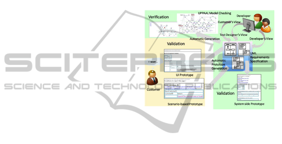
process as shown in Figure 1.
Figure 1: Validation and Verification of Requirements
Analysis Model.
At the second step, the developer refines the model
from the feasibility of the requirements for each use
case. To achieve the feasibility of the requirements
specification, the developers must confirm that a
sequence of actions and data flows within the system
partition of the activity diagrams can produce the
expected output data from the specified input data.
System side Prototype helps the developers to
confirm that input data being defined by the user can
be transformed into entity data of the system.
Moreover, actions in the system can be specified
with data life cycle functions. Data life cycle means
that every data in a system has such four functions
as create, read, update and delete. These functions
are called CRUD of data, and several general rules
are set on them for the consistecy.
After the developer has revealed the feasibility of
the required interaction, the model is translated into
the UPPAAL (UPPAAL, 2010) model which is one
of known model checking tools. He/she can
exhaustively verify whether the requirements
analysis model meets the other required conditions.
At this time, the behavioural relations between these
four CRUD functions can set several rules in the
basic system behaviour on every entity data on the
requirements specification (see Figure 5).
ICEIS 2012 - 14th International Conference on Enterprise Information Systems
%p
3.2 A Method with Automatic
Prototype Generation
At requirements analysis phase, developers extract
requirements for a system from customers and
generally specified them by defining semiformal
documents. Recently, many developers have been
getting to use UML, so that requirements
specifications can be defined more formally. We
have proposed a method of model-driven
requirements analysis using UML. We analyze
functional requirements of services as well as use
case analysis. Especially, because what customers
essentially want to do obviously appear within the
interaction between a user and a system, our method
proposes to clearly model the interaction.
To put it concretely, we specify business process
as a service from the following four viewpoints.
Based on the business rules, what kinds of
input data and the conditions are required in
order to execute a service correctly?
To observe the business rule, what kinds of
conditions should be required in case of not
executing the service? Moreover, how the
system should treat these exceptional cases?
According to these conditions, what kinds of
behaviors are required in order to execute the
service?
What kinds of data are outputted by these
behaviors?
Based on the above mentioned four viewpoints,
both business flow and business entity data which
are required to execute the target business are
defined by activity diagrams and a class diagram in
UML.
An activity diagram specifies not only normal
and exceptional action flows but also data flows
which are related with these actions. An action is
defined by an action node and data is defined by an
object node being classified by a class which is
defined in a class diagram. Accordingly, these two
kinds of diagrams enable us to specify business flow
in connection with the data. This is one of the
features of our method on how to use activity
diagram and class diagram. Especially, the
interaction between a user and a system includes
requisite various flows and data on user input,
conditions, output to execute a service correctly.
The second feature is that an activity diagram has
three kinds of partitions being named User,
Interaction, and System. This is because that these
partitions enable us to easily recognize the following
activities; user input activities, interaction activities
between a user and a system which are caused by the
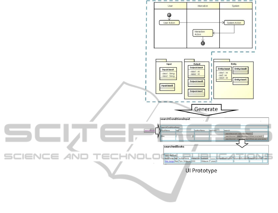
Figure 2: UI Prototype.
conditions to execute a service, and the resulted
output.
The third feature is that we use an object diagram
to define concrete data for each activity, because
concrete valid data make it easy for us to confirm
business process.
The fourth feature is that a prototype which
consists of Web pages written in HTML is
automatically generated from these three kinds of
diagrams. The prototype which is a kind of final
product model enables the customers to confirm
plainly and easily the requisite business flows in
connection with the data. The generated prototype
describes the required target system except user
interface appearance and internal business logic
processing. Moreover, the prototype enables the
developer to confirm and understand the
correspondence between his/her models and the final
system. The developer defines three kinds of
diagrams along requirements analysis from such
different viewpoints as action flows, data flows and
the structure, and the concrete values. The
automatically generated prototype enables him/her
to easily understand the consistency between his/her
models and the target system. To be able to fully
understand the correspondence between each
diagram and the target system, a prototype can be
Quality Improvement of Requirements Specification using Model Checking Technique
%p
generated whenever the developer want to confirm
at the requirement analysis phase. The requirement
analysis model is defined by using the astah* (astah)
of a modeling tool.
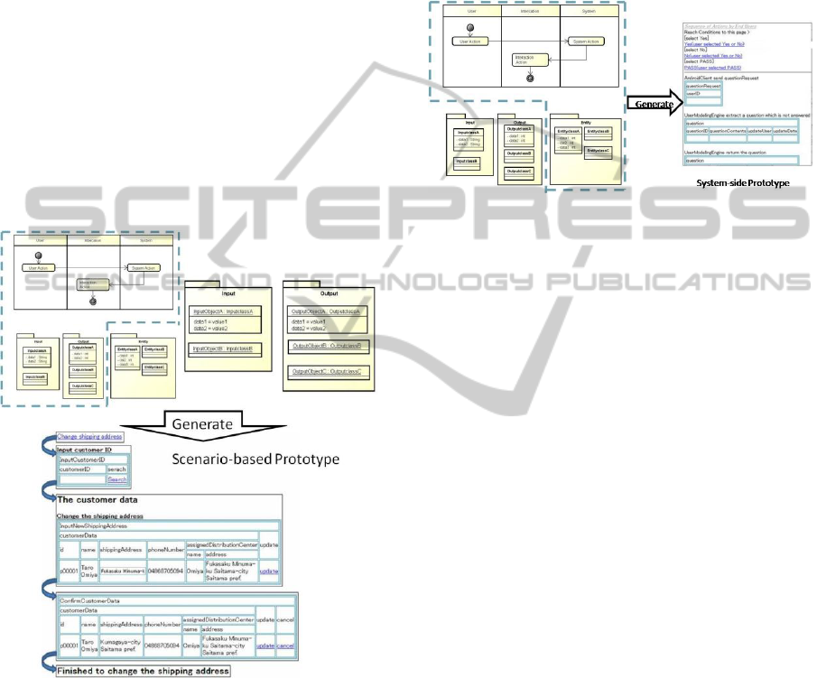
3.3 Scenario-based Prototype
At the stage where almost business flows and data
structure have been defined from the above
mentioned viewpoints, we define scenarios in which
each flow has valid concrete data. We can get
scenario-based prototypes to confirm that every flow
correctly processes appropriate concrete data as a
service. From another viewpoint, this work can be
regarded as a work of defining integrated test cases.
We can automatically generated integrated test cases
from the requirement analysis model. The generated
test cases can be tested by Selenium IDE (Slenium
IDE).
Figure 3: Scenario based Prototype.
3.4 System-side Prototype
At the stage where the customers have confirmed
that the prototype satisfactorily represents their
requirements, we can say that the first goal of the
requirements specification have achieved. To
achieve the second goal of the requirements
specification, the developers must confirm that a
sequence of actions and data flows within the system
partition of the activity diagrams can produce the
expected output data from the specified input data.
The system side prototype helps the developers
to confirm the following facts.
Input data being defined by the user can be
transformed into entity data of the system.
The existent entity data that should be generated
via the other use cases and the above mentioned
entity data can generate the target output data
following the specified action sequence.
Figure 4: System-side Prototype.
4 VERIFICATION OF
REQUIREMENTS
SPECIFICATION USING
MODEL CHECKING
TECHNIQUE
4.1 Model Checking Technique
Model checking has been favored as a technique that
helps improve reliability in the upper process of
software. The model-checking tool uses temporal
logic. It is inspected whether to fill a property in
which a model is demanded from a system. When
the specified state is not filled, the tool presents a
counterexample. The process can be confirmed by
the simulation facility. There are several model-
checking tools, including UPPAAL, SPIN and
PathFinder. Although model checking technique is a
promising approach, it is generally difficult to
specify an appropriate formula so that the system
meets the property at the early stage of requirements
analysis because of the ambiguity. However, if the
requirements specification is defined as specifically
as the above mentioned, we can verify the data life
cycle of every entity data in the system.
4.2 Verification Process
We can verify that each entity class data is
guaranteed the life cycle during all action flows in
the whole activity diagrams as follows.
ICEIS 2012 - 14th International Conference on Enterprise Information Systems
%p
1. Each activity diagram of the validated
requirements analysis model is automatically
translated into a UPPAAL model.
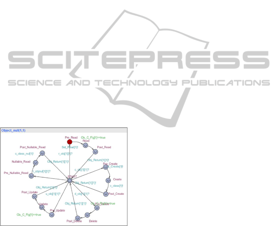
2. Generate concrete lifecycle model for each
extracted entity class from the CRUD
behavioral model as shown in Figure 5. These
models can be synchronized by the common
CRUD actions
3. Several rules on execution order of CRUD
functions are checked on UPPAAL model.
Define a path formula :
A[] (Object null(1,1).Pre Read imply
Create(1).EXECUTED)
This formula means that an entity object must be
created before it is read.
4. When the result of UPPAAL simulation shows
"Property is not satisfied", the counterexample
is required to be investigated. In this case, we
can detect the location in which the entity
object will be read though it has not yet been
created. The red location on Figure 5 denotes
an occurrence of deadlock. The support tool
shows the correspondence action in the activity
diagram to the location in which the object will
be read.
The path to the detected action is investigated so
as to detect the cause. The model is modified and we
can try to recheck on UPPAAL model.
Figure 5: Behaviour of CRUD Functions in UPPAAL
Model.
5 RELATED WORKS
Several researchers have proposed respective formal
approach to verification of some specified features at
the upper process of software development. Yatake
(Yakate et al., 2005) verified that all object states
satisfy the invariant conditions between
collaborative object behaviors by using a theorem
proving system. However, it takes a large quantity of
strict definitions to clarify all the actions and data
related to the invariant. Generally it is difficult to
carry out such strict works at the changeable phase
such as requirements analysis.
It is important to do stepwise refinement of the
specification by checking several verifiable features
at the early stage of software development. Choi
(Choi et al., 2005) proposed a verification method of
the consistency between the page transition
specification on a Web-based system and the flow
chart defining the process flows. We also proposed a
common verifiable feature in enterprise systems
such as the rules on CRUD of entity data. Moreover
we can automatically generate some path formulas.
Achenbach (Achenbach and Ostermann, 2009)
compared the abstraction techniques in various
model-checking tools and applied these tools to real
world problems. For example, the open/close
behavior of the File IO stream was modeled using
the transition between states such as open, close, and
error. This approach is very similar to ours.
However, unlike our approach, this paper did not
discuss the method on the assumption that the
requirements specification has been validated by the
customers.
6 CONCLUSIONS
We could detect several inconsistencies among
entity class data life cycle through some experiments.
This made it clear that some action flows in a use
case were oversight.
Model Driven development is a promising
approach to develop high quality software products
efficiently. However, to obtain high quality source
codes, appropriate models that meet customer's
requirements should be well defined at the
requirements analysis phase which is a start point of
the system development. This paper proposed a
verification method with UPPAAL to improve the
feasibility of requirements specification. Although
detectable property is related to general data life
cycle at present, we will apply this method to the
relation between the attributes of data.
REFERENCES
Paulo, Rogerio; Carvalho, Adriano,Towards model-driven
design of substation automation systems, 8th
Quality Improvement of Requirements Specification using Model Checking Technique
%p

International Conference and Exhibition on CIRED,
pp.1 5, 2005.
Monteiro, R.; , Mdgore:
Towards Model-Driven and Goal-Oriented
Requirements Engineering, 18th IEEE International
Requirements Engineering Conference, pp. 405 406,
2010.
Forward, A.; Badreddin, O.; Lethbridge, T.C. Towards
combining model driven with prototype driven system
development, 21st IEEE International Symposium on
Rapid System Prototyping (RSP), pp.1 7,2010.
Rational Software Modeler, http://www.06.ibm.com/
software/jp/rational/products/design/rsm/.
S. Ogata, and S. Matsuura, A UML-based Requirements
Analysis with Automatic Prototype System
Generation, Communication of SIWN, Vol.3, Jun.
2008, pp.166-172.
S. Ogata. and S. Matsuura, A Method of Automatic
Integration Test Case Generation from UML-based
Scenario, Wseas Transactions on Information
Science and Applications, Issue 4, Vol.7, Apr 2010,
pp.598-607 .
UML, http://www.uml.org/
IEEE Computer Society, IEEE Recommended Practice for
Software Requirements Specifications, IEEE Std 830
(1998).
Achenbach, M., Ostermann,
Analysis and Manipulation, Proc. of .SCAM ’09., pp.
Bao, T., Jones, M.D. 2009. Test Case Generation Using
Model Checking for Software Components Deployed
into New Environments. Proc.of ICSTW ’09, pp. 57
66,2009.
Y. Aoki and S. Matsuura, A Method for Detecting
Unusual Defects in Enterprise System Using Model
Checking Techniques, Proc of The 10th WSEAS
International Conference on Software Engineering,
Parallel and Distributed Systems, pp., 2011.
UPPAAL, http://www.uppaal.com/, 2010.
astah*, http://www.change-vision.com/
Slenium IDE, http://seleniumhq.org/
Kenro Yatake, Toshiaki Aoki, Takuya Katayama,
Collaboration-based verification of Object-Oriented
Models, Computer Software, Vol.22, No.1, pp.58-76,
2005. (in japanese)
Eun-Hye Choi, Takanori Kawamoto, Hiroshi Watanabe,
Model Checking of Page Flow Specification,
Computer Software, Vol.22, No.3, pp.146-153, 2005.
(in japanese)
Engineering Abstractions
pp.137-146
ICEIS 2012 - 14th International Conference on Enterprise Information Systems
%p
