
DEVELOPMENT OF ORIGINAL OPTICAL AND
QUANTUM ELECTRONICS DEVICES FOR
APPLICATIONS IN COMMUNICATIONS,
METROLOGY AND SCIENCES
Hristo Kisov, Margarita Deneva
,
Elena Stoykova, Marin Nenchev
Technical University of Sofia, Branch Plovdiv, Bulgaria
mdeneva@yahoo.com
Keywords: Interference wedged structures, WDM-system, multi-wavelength lasers, optical transistor, laser with fixed
wavelength at atomic absorption line, injection-locking linear laser amplifier.
Abstract: The goal of the report is to present the development – principles, theories and computer simulations,
experiments and practical realizations, of original and competitive methods, elements and devices for
quantum electronics, optical communications, metrology, remote sensing and sciences: multi-channel
WDM system with independent tuning of each input/output, multi-wavelength laser with independent
control of each wavelength, lasers with emission, spectrally fixed at reference atomic absorption line,
injection-locking laser system for high (~10
6
-10
8
) and linear amplification of low-power (~ µW, nW)
modulated laser light, optical analogue of the transistor action – optical transistor, system for remote (up
to kilometres) measurement of small (mm) translational elongation – shrinking of objects, new solution of
tunable sub-nanosecond lasers and lasers with rectangular nanosecond (~1 ns) pulse emission, including
controlled duration and tunable wavelength. The basic element of the devices developed is stable and
compact interference wedged structures in new composite solution with very narrow transmission
(≤ 0.01 nm) in relatively large spectral range (≥1 nm). The laser active media used are solid-state,
semiconductor and dye.
1 INTRODUCTION
The report is a review of our recent results,
concerning the further development of original
quantum electronics and optical devices with a
potential for competitive applications in optical
communications, metrology, scientific work, and
atmospheric pollution monitoring. The aim of the
report is to present as a whole complex our last
achievements in the development – experiments,
theories, and practical realizations of an original
WDM system with independent tuning of each input
and output, system for remote (to kilometres)
measurement of small (mm) translational elongation
- shrinking of objects, optical transistor, multi-
wavelength lasers with independent control of each
wavelength and with wavelength emission in single
beam or in closely parallel or coaxial beams, the new
solution of tunable sub-nanosecond lasers, the lasers
with emission, spectrally fixed at reference atomic
absorption line. The basic elements, used and studied
by us are a wedged interference structure (variation
of the Fizeau Wedge), including some researched of
found by us new properties. The essential part of the
results is obtained in our group at the Technical
University of Sofia, Branch Plovdiv and the
University CNAM-Paris, the University of North
Paris and the University “Sent Quentin” – Versailles,
France. The principal authors’ publications from the
last years, where the discussed here results are given
in details, are the firs 13 articles, given in the
References at the end of the paper. The authors of
the report, that are the main co-authors of the noted
works, have selected and systematized the materials;
also the essential part is based on their propositions –
primarily given in their patents and previous articles
followed the noted firs ones, except the last well
known laser book [Svelto,1998]. The report includes
also completely new, non-published results. The
articles of the other authors, related with the subject
of the presentation, are given as citation in the noted
146
Kisov H., Deneva M., Stoykova E. and Nenchev M.
DEVELOPMENT OF ORIGINAL OPTICAL AND QUANTUM ELECTRONICS DEVICES FOR APPLICATIONS IN COMMUNICATIONS, METROLOGY AND SCIENCES.
DOI: 10.5220/0005415201460157
In Proceedings of the First International Conference on Telecommunications and Remote Sensing (ICTRS 2012), pages 146-157
ISBN: 978-989-8565-28-0
Copyright
c
2012 by SCITEPRESS – Science and Technology Publications, Lda. All rights reserved

authors’ publications. Following the actual authors’
professional activity, the report concerns mainly the
technical aspects of the problems. Nevertheless, the
necessary physical moments to clarify the principle
of the developed methods and devices are also given
shortly.
The general objective of the work is to establish
these new and effective devices in science and
practice as novel components of the main hardware
basis in the indicated areas. In parallell, new
knowledge in the field of quantum electronics and
optical interferometry is obtained. The envisaged
solutions have encountered their preliminary
positive approbation firstly in the working
laboratory models as well as in the cited below
recent publications in the specialized journals.
2 NEW ELEMENTS AND DEVICES
IN ACTUAL DEVELOPMENT
2.1 Original optical elements based on
wedged interference structures and
their applications
Furstly, we will present the further development and
examine thoroughly the original optical elements
and system for noted in the introduction
applications. Proposed devices are based on the use
of the wedged interference structure of Fizeau type
Interferometer - Interference Wedge (IW). The
development include ideas, experiments, theory and
proposed applications developed by us. It is
applicable in the case of limited diameter beam
illumination [Nenchev, 1982; Stoykova, 2010;
Nenchev, 1993; Stoykova, 1993; Deneva, 2007;
Deneva, 1996]. The new proposition, except our
previosly introduced new optical element based on a
Reflecting Interference Wedge [Nenchev, 1982],
includes a new WDM (wavelength division
multiplexing) element with an important property
allowing spectral tuning of inputs/outputs in the
simplest manner. The importance of WDM
structures for the optical communications is
undisputable and is described in the most popular
textbooks. Also, we describe the new system with
IW for remote (meters, kilometers) measurement of
the translational expansion and shrinking of objects.
The principle of our proposed WDM structure
can be clarified with the Figures given below. The
interference wedge (IW) of thickness of the order of
micrometers plays the role of a spectrally selective
filter and a channel coupler, being a near totally
reflecting mirror for the non-resonant wavelengths.
The new, generalizing theoretical and experimental
physical treatment of the IW is described in our cited
papers [Stoykova 2010; Nenchev 1993; Stoykova
1996].
The Fizeau interferometer or interferential wedge
(IW) consists of two reflecting plane surfaces
separated by a gap with linearly increasing
thickness. A low-reflectivity coated wedge has been
used before us as un effective tool in surface
topography, as a high-resolution broadband wave-
meter. Multiple-beam interference in IW has been
addressed for implementation of phase-shifting
Fizeau interference microscopy. As a rule,
theoretical and experimental analysis of the IW
properties by the other authors were conducted
mainly for the case of infinite plane-wave
illumination assuming an extended wedged
structure; different wedge applications have been
also analyzed for this particular case. Inspired by
IW incorporation in laser design, over the recent
years we focused our efforts on the study of compact
wedged interference structures under illumination
with a narrow light beam of small diameter. We
have succeeded to reveal unique properties of the
IW when illuminated with laser light, and to propose
various applications, thus insuring the IW as a
competitive optical element in laser resonator design
[Deneva, 2007; Louyer, 2003; Stoykova, 1996;
Goris-Neveux, 1995]. A high-reflectivity coating IW
with thickness of tens of millimetres has spectral
resolution comparable to that of the Fabry-Perot
interferometer, but at additional advantage of linear
spectral tuning by means of translation in its plane.
Such IW, with apex angle of 5–100 μrad and
thickness of 5–500 μm has been used by us in laser
resonators technique to create two-channel
resonators with independently controlled
characteristics of the produced two-wavelength
emission, as a spectrally selective reflecting or
transmitting optical element of resonant wavelength
easily adjustable by translation of the interferometer.
Selective wedge transmission and reflection has
been used for continuous tuning of the selected
mode in high-purity single mode lasers,
unidirectional lasing in ring resonators, two-
wavelength laser operation, narrow line selection
and tuning of wide-gain lasers.
A simple and effective solution of a multi-
wavelength spectrally selective resonant structure
for two-wavelength lasers with independent tuning
at each wavelength has been proposed by the authors
[Nenchev, 1981; Deneva, 2007; Louyer, 2003,
Development of Original Optical and Quantum Electronics Devices for Applications in Communications,
Metrology and Sciences
147
Gorris-Neveux, 1995]. It makes the use of valuable
optical features of the IWs. In particular, we
advanced a reflecting IW as a completely new laser
spectral selector. The proposed structure has been
patented and successfully applied in multi-
wavelength laser technology for dye, Ti:Sapphire
Yb:YAG, and semiconductor lasers.
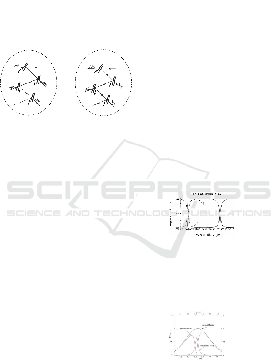
Multiplexing operation Division operation
Figure 1. Schematic presentation of new WDM structure.
Generally speaking, it could be considered as a new
and competitive solution of a WDM element for
optical communications.
The high-reflectivity coatings IW of thickness of
5-300 μm acts simultaneously as a spectrally
selective filter and a channel coupler, being a nearly
totally reflecting mirror for the off-resonant
wavelengths. In addition, tuning of the transmission
maxima is provided by simple translation of the IW
in its plane. Figure 1 represents schematically the
operation of the proposed new WDM structure for
the cases of multi-wavelength input or output beam.
The tuning of each output by translation of the
corresponding IW in its plane does not affect the
geometry of the structure and the characteristics of
the other outputs respectively. Also, as it is clear
from the figure, the structure gives the possibility to
obtain superposition of individual beams which have
passed through each IW, thus serving as a multi-
beam multiplexing element for the spectrally
different beams (each of them being a resonant beam
for the corresponding IW and off-resonant beam for
the other IWs).
Analysis of the WDM element requires first to
analyze the behaviour of a separate IW for laser
(coherent) beam illumination.
We adopted the mathematical model for
computer simulation and developed an adequate
description of transmittance and reflection of the IW
for a limited diameter laser (coherent) beam (~1-
1.5 mm). [Nenchev, 1993; Stoykova, 2010] Thus,
our treatment differs essentially from the plane-wave
illumination approach.
The detailed calculations are given in our works
[Stoikova, 2010; Nenchev, 1993; Stoykova, 2001].
The calculations were made for two types of
interference wedges. The first one is a “sandwich
type” IW, formed by sequential layer-by-layer
deposition of a dielectric reflective coating of
reflectivity 0.9 on both sides of the glass plate,
which represents a wedged transparent layer with
optical thickness of 5 μm. The other type of the IW
is the silica wedge with optical thickness of 300 μm
having dielectric layers on both surfaces of equal
reflectivity of 0.9 in a spectral region of ~ 30 nm
around the wavelength of 630 nm. The apex angle of
both wedges is α = 0.05 mrad. The described IWs,
which are of essential interest as high-resolution
spectral selective elements, are simple for
production and use. The “sandwich type” IW is very
convenient for application in the new WDM
structure due to its compactness.
λ
1
?
3
?
4
multichannel output beam
?i
IW
1
IW
2
IW
3
λ
1
… λ
i
λ
λ
λ
λ
2
IW
4
tune λ
1
tune λ
4
tune λ
3
tune λ
2
λ
1
?
3
?
4
multichannel output beam
?i
IW
1
IW
2
IW
3
λ
1
… λ
i
λ
λ
λ
λ
2
IW
4
tune λ
1
tune λ
4
tune λ
3
tune λ
2
λ
1
?
3
?
4
multichannel output beam
?i
IW
1
IW
2
IW
3
λ
1
… λ
i
λ
λ
λ
λ
2
IW
4
tune λ
1
tune λ
4
tune λ
3
tune λ
2
λ
1
… λ
i
(μW)
λ
1
?
3
4
multichannel input beam
?i
IW
1
IW
2
λ
λ
λ
λ
2
IW
4
tune λ
1
tune λ
2
tune λ
4
tune λ
3
IW
3
λ
1
… λ
i
(μW)
λ
1
?
3
4
multichannel input beam
?i
IW
1
IW
2
λ
λ
λ
λ
2
IW
4
tune λ
1
tune λ
2
tune λ
4
tune λ
3
IW
3
λ
1
… λ
i
(μW)
λ
1
?
3
4
multichannel input beam
?i
IW
1
IW
2
λ
λ
λ
λ
2
IW
4
tune λ
1
tune λ
2
tune λ
4
tune λ
3
IW
3
A typical curve, calculated for illumination with
a CW laser Gaussian beam in the region of its flat
front (flat-concave resonator, near the flat output
mirror), is shown in Figure 2. We see that the IW is
a highly transmissive narrow-line filter for the
resonant wavelength and approximately totally
reflecting mirror for the off-resonant wavelength.
Figure 2. Calculated transmission and reflection curves as
a function of the wavelength for a “sandwich”-type IW
(CW laser beam illumination).
As a second step, we have studied wedge
behavior for illumination with short laser pulses,
including the sub-nanosecond light pulses. The
calculations are made at different wavelengths near
~ 0.6 μm. The obtained results are similar to those in
the case of CW beam illumination.
Figure 3. Transmission and reflection for pulse
illumination (0.5 ns pulse duration); e=5 μm.
First International Conference on Telecommunications and Remote Sensing
148
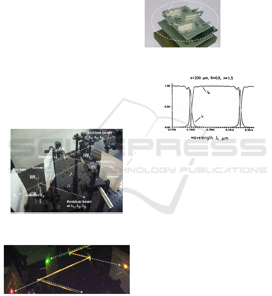
Figure 3 gives the typical computed curves for
the “sandwich type” IW irradiated with pulses of
duration of 0.5 ns (the axis x in Figure 3 gives the
distance along the beam impact area from an
arbitrary chosen zero-point) [ Nenchev, 2011].
As it can be seen from the depicted curves, the
transmission and reflection properties of the wedge
do not change essentially. Transmission reaches
about 60 % for the pulse duration of ~ 0.1 ns that
may correspond to frequency repetition rate of ~ 10
GHz. Therefore, the presented calculation shows
feasibility of the proposed WDM structure.
We realized experimentally our WDM structure
for the case of CW beam illumination using a
laboratory model of free-communication system. We
formed a single laser beam by exact superposition of
the emissions of three CW lasers – two He-Ne lasers
emitting at 0.63 μm and at 0.59 μm respectively and
the frequency doubled Nd:YAG laser (0.53 μm).
The beam diameter was ~ 1 mm. Figure 4(a)
presents the WDM structure, composed of 3
“sandwich type” wedges with thickness e = 5 μm,
each of them tuned to one of the wavelengths in the
green, yellow and red spectral regions, respectively.
Figure 4(a). The experimental set-up presents the realized
WDM device, composed of 3 wedges, each of them to a
separate channel – green, yellow and red, respectively.
Figure 4(b). Visualization of the channel-separation
(colors) by the new WDM-arrangement in the laboratory
model
As it is shown in Figure 4(b) by using smoke
visualization and screens, wavelengths separation
has been achieved. By translation of the wedges, we
can independently tune the resonance and the given
output. The laboratory WDM is shown in Figure 5.
IW
IW
1
1
IW
IW
2
2
IW
IW
3
3
Figure 5.
Realization of the
compact working
experimental model
of the proposed
WDM structure
The calculation shows the same type of
dependences for the silica gap IW with optical
thickness of 300 µm (Figure 6(a) ) .
The essential advantage of this silica gap thick IW is
the higher spectral resolution in comparison with the
“sandwich type” structure whose thickness is
technologically limited to few µm, and respectively
does not permit to obtain a transmission line low
than few part of nanometers. However, there is the
problem related of obtaining a selection by the
standard IW structure of a narrow line in
combination with high separation between the
resonant lines (Figure 6(a)). The calculations show
that there are completely similar dependence
between the width of the selected line δλ and the
spectral distance ∆λ between the lines as this one for
FPI - e.g. δλ = ∆λ/F, where F is the fines factor,
depending on R. Thus the desired low value of δλ
leads to low value of ∆λ .This limits the selectivity
of the channels in optical communication system.
The principle of our solution of this problem is
based on the use of composite wedged interference
structure. It can be understood from Figure 6(b)
where is given schematically one example of
composed two-component structure.
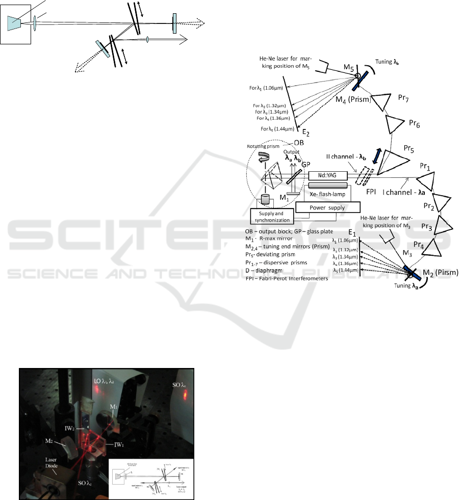
Figure 6(a). Calculated curves as in Figure 3, but for thick
silica-gap 200 μm IW.
Incident beam – λ
1
, λ
2
, λ
3
IW
1
selected λ
1
selected λ
2
selected λ
3
screen
screen
IW
2
IW
3
Residual beam at λ
1
, λ
2
, λ
3
screen
Incident beam – λ
1
, λ
2
, λ
3
IW
1
selected λ
1
selected λ
2
selected λ
3
screen
screen
IW
2
IW
3
Residual beam at λ
1
, λ
2
, λ
3
screen
Development of Original Optical and Quantum Electronics Devices for Applications in Communications,
Metrology and Sciences
149
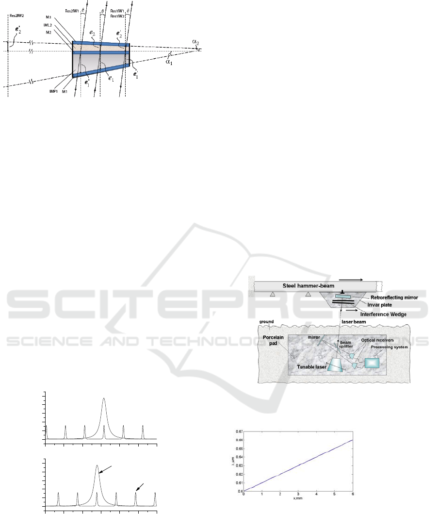
Figure 6(b). Schematic of the new composite wedged
interference structure.
It consists of one thick wedge e.g. e
1
=200 µm
optical thickness silica glass wedge with two
dielectric mirrors at each wedge plane with
reflectivity of R=0.95%. The wedge angle α
1
of the
plate in the example is α
1
= 200 µrad. On the one of
the mirrors is lay a transparent wedged layer with
thickness e
2
=10 µm and wedge angle α
2
. The
relatively simple calculations give that if the angle
α
1
and thickness e
1
, and the angle α
2
and the
thickness e
2
are chosen to be in the relation
α
2
= α
1
.e
2
/ e
1
the change of the resonant maximums of both
connected wedges with the translation of the
composite system in its plane is exactly equal. In
this system the thick wedge gives a very low
spectral width of the transmission of all system
(~0.05 nm) and the thin wedge selects only single
resonance of the thick wedge at high spectral range
(~ 15 nm and higher). Typical example of computer
calculated resonances at the described system is
given in Figure 6(c).
Figure 6(c). Computed transmission of the composite
wedged structure, formed by two IW (10 μm and 200 μm)
with convenient wedge angles and the tuning (see the text)
As a second task, we have proposed new and
attractive utilization of the IW specific properties by
designing devices, which allow distant (from few
meters to millimeters) laser measurement of small
(~mm) linear translation of a rigid object.
The principle of our device can be understood
from Figure 7, which shows as an example -
measurement of small linear stretching of a steel
hammer-beam due to change of the IW transmission
resonance in the beam incident point.
The set-up contains a comparative system of one
beam-splitter and two photo-receivers. One of them
records that part of the emitted beam, which forms
reference intensity and the other one records the
light transmitted by the IW. Due to translation of the
IW, the transmitted light decreases. By tuning the
laser, we can obtain new resonant wavelength, λ
2
,
corresponding to the new wedge thickness.
Indication for this is the new peak in the transmitted
light that is recorded by the corresponding receiver.
From λ
and λ
1 2
it is easy to calculate the translation
distance ∆x, of the invar plate. Figure 8 proves the
high sensitivity of the proposed method. For high
precision measurements of translations in sub-
millimeter region, a single-mode semiconductor,
Titanium Sapphire or dye lasers can be used.
Figure 7. Device based on IW for distant measurement of
small translation of a rigid object in its plane
.
642 643 644 645 646 647 648
0
20
40
60
80
100
200 μm
λ
,
n
m
10 μm
642 643 644 645 646 647 648
0
20
40
60
80
100
P
T
, %
P
T
, %
For the case of remote (meters, kilometers)
measurement of the translational stretching -
contraction of objects the second type of system,
which is other variant of the idea, discussed above,
is developed. This system eliminates the increasing
of the diameter of the laser beam due to the natural
divergence, also the fluctuation of the illuminated
intensity and the need of exact beam direction on
Figure 8. Calculated
dependence of the
resonance wavelength
at different points
along the IW.
First International Conference on Telecommunications and Remote Sensing
150

the Interference Wedge (which is a small dimension
element). The action of the system is clarified from
given Figure 9.
Here, we introduce an Ulbricht
sphere and lens, as it is shown in Figure 9, to
eliminate the noted above problems for remote
measurement at long distance. The radio-transmitter
system or reflection of modulated by information
about translation part of the incident light transmit
the two signals in the processing system. Thus, we
obtain the correct relative value of the transmitted
signal, what eliminate the influences of the beam
intensity fluctuations and the incident place of laser-
beam cross-section, illuminating the lens.
Figure 9. Device for remote (kilometers) measurement of
small translations of a rigid object in its plane that uses
IW and Ulbricht sphere.
The developed laser-Interference wedge devices can
be of interest to control the metal or concrete
hammer-beam length variation (with the temperature
or earthquake) of bridges, of platforms for oil
extraction in the sea, of walls of the buildings etc.
2.2. Original multi-wavelength lasers
with independent control of each
wavelength using the WDM
structures developed in 2.1.
An important goal is the achievement of two- and
multi-wavelength generation of nano- and sub-
nanosecond pulses with implementation of our
group’s original methodology as well as
development of multi wavelength generators of the
same type based on semiconductor active media
[Nenchev, 1995].
Our group has substantial expertise in the
development of two-wavelength lasers [Deneva,
2010; Louyer, 2003; Slavov, 1998, Gorris-Neveux,
1995; Nenchev, 1981]. Using our original approach
we were the first in the world to develop with the
corresponding theoretical and experimental
background two-wavelength F-centers, Ti-Sapphire
(in pulsed mode) and Yb:YAG lasers, (in a CW
diode pumped mode) – [Loyer, 2003; Goris Neveux,
1995]). The laser solutions are based on our
proposed effective multichannel resonator with a
complex selector-coupler structure based of IWs
[Nenchev, 1981]. Using the described above multi-
channel WDM element new and simple solution of
multi-wavelength lasers are proposed with
independent tuning of each wavelength. Two types
of solution are given in Figure 10(a) and 10(b). The
scheme in Figure 10(a) is solution in which the
emission of the two wavelengths is in single laser
output beam. For many cases where single volume
needs to be illuminated exactly (e.g. in remote
atmosphere pollution control) and high speed
processes (e.g. explosion) this solution is
advantageous. The difficulty for multi-wavelength
operation is related to strong wavelength
competition effects in homogeneously broadened
active medium – e.g. dye, semiconductors. It follows
that it is necessary to make a very precise balance
for net gain for all wavelengths at each tuning or
strongly limit the tuning range around the gain
maximum – in its flat part. The second scheme with
closely spaced parallel beams at each wavelength –
in Figure 10(b) - eliminates the problem of
competition, however the laser light at the separated
wavelengths acts upon different parts of the
illuminated volume (superposition can be obtained
after focusing in small length of ~ mm).
Figure10. WDM multi-wavelength laser resonator
schemes with independent tuning at each wavelength; (a)
–with output in single beam, (b) – with closely parallel
outputs.
Except the previously realized, used and
described in the specialized literature dye, Ti-
Sapphire, F-colour centres and Yb:YAG lasers, in
our recent works we have practically developed a
two-wavelength semiconductor laser. The laser
emits at two independently tunable wavelengths in a
single beam. To obtain a small diameter of the
Development of Original Optical and Quantum Electronics Devices for Applications in Communications,
Metrology and Sciences
151
incident beam at the selected IWs, we modified the
scheme in Figure 10(a) using the focussing and the
flat end mirrors as it is shown in the Figure 11. We
have realised (Figure 12) such two-wavelength
semiconductor laser using a red laser diode with
antireflection coated output surface. The laser
Figure 11. Schematic diagram of the modified resonator,
given in Figure 10(a) and adapted for two-wavelength
generation with independent tuning of each wavelength in
large beam semiconductor active media.
operates successfully at two wavelengths. As a rule
the lasing starts firstly in one of the channels. To
obtain also lasing in the other channel we slowly
increased the losses for the started generation, in
practice by misalignment of the end mirror in its
channel. This can be obtained if the wavelength is
spectrally near the maximum of the gain. At each
tuning of one wavelength it was necessary to arrange
again the losses at the generated channel to obtain
the lasing also at the second wavelength. In this
manner tuning range of ~ 4 nm for each wavelength
in two-wavelength operation can be achieved. By
oscilloscope studies we found that both wavelengths
are generated simultaneously. This laser can be
useful in some experimental works needed in two-
wavelength operation. Our next work is related to
realization of the second, wavelength competition
less, scheme given in Figure 10(b). The new solution
is combined with passive self-injection [Keller,
2000] what abruptly increases the laser efficiency.
Figure 12. Photograph of the operating two-wavelength
semiconductor red laser. The generation is at two
wavelengths λ
1
and λ
2
in separated reference outputs
and in main, common output
.
2.3 Actual our development of a high-
power two-wavelength wavelengths
competition-less Nd:YAG laser
Earlier [Nenchev, 1978], we have patented a
flashlamp pumped laser where single active element
operates in two parts separately and at two different
wavelength. Actually, we have developed this
technique using single, flash-lamp pumped (~150 J
pump) Nd:YAG crystal to obtain simultaneous or in
controlled manner generation at two chosen lasing
IW
1
IW
2
tune λ
1
tune λ
2
low-power signal
output at λ
1
low-power signal
output at λ
2
laser output
λ
1
+ λ
2
M
1
M
2
AR front face
diode-laser
L
L
1
IW
1
IW
2
tune λ
1
tune λ
2
low-power signal
output at λ
1
low-power signal
output at λ
2
laser output
λ
1
+ λ
2
M
1
M
2
AR front face
diode-laser
L
L
1
Figure 13(a). Schematic of the two-wavelength, flashlamp
pumped, Q-switched, laser that uses two separate parts of
a single Nd:YAG crystal and prisms selective structure.
lines - pair-combination from the possible
generating lines: 1.06 µm (to 0.8 J), 1.32 µm, 1.34
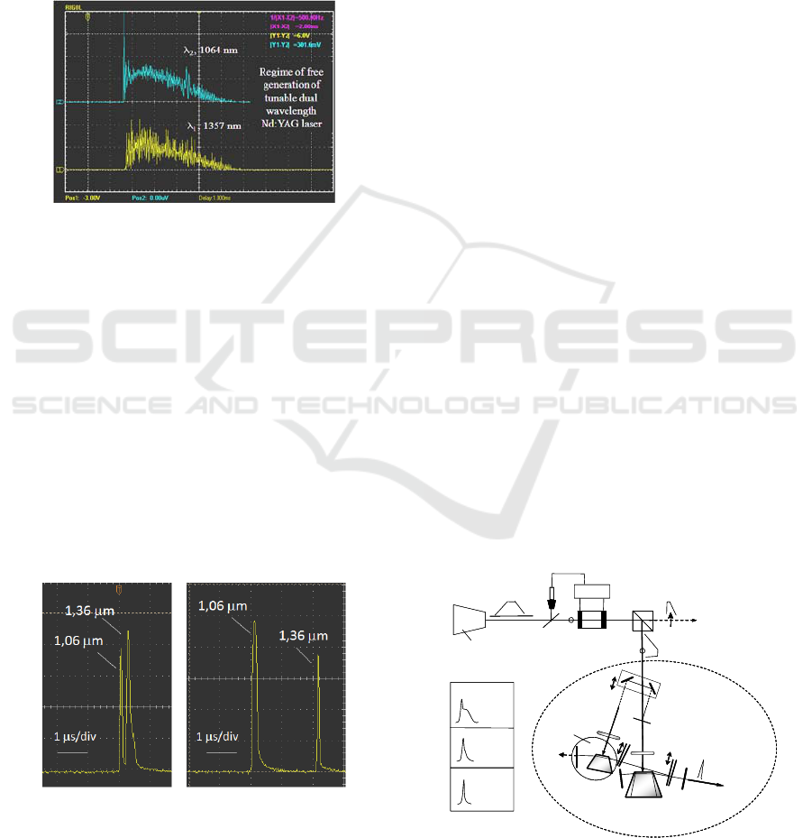
µm, 1.36 µm (to ~ 0.14 J) and 1.44 µm (to ~0.03 mJ,
none well reproducible) and avoiding the limiting
wavelength-competition effect. The laser (Figure
13(a)) can also operate at two chosen modes at
different frequency distance from the standard for
single cavity lasers (c/2L). We use the generations in
two separate parts of the single, flashlamp pumped
Nd:YAG crystal in two manner: i) in coaxial
separation and ii) in two closely spaced parts by
prism selected-tuning resonators (for the single-
mode case with introduced glass-plate Fabry-Perot
interferometers).
The design of this laser was developed both
theoretically and with practical realization, both for
free lasing and Q-switched regime. To generate any
First International Conference on Telecommunications and Remote Sensing
152
desired pair of the given lines we employ a rotated
prism (axis in the plane or perpendicular) Q-switcher
that is completely non-sensitive of the different
wavelengths. The scheme of experimental
realization of the described two-line and two-mode
laser is shown in Figure 13. The typical oscilloscope
traces of simultaneous generation at two markedly
different lines – 1.06 µm and 1.36 µm, obtained for
conveniently chosen parameters of both resonators
and lasing volumes are shown in Figure 13(b).
Figure 13(b). Simultaneous generation at 1.06 µm and
1.36 µm in free-running regime (for conveniently chosen
parameters).
For the theoretical study we have adapted the
rate differential equations system [Svelto, 1998] to
obtain the optimal conditions for desired operation.
The theoretical considerations show the
possibility to control the energy, time length of the
pulses and delay between them, including also the
possibility for simultaneous Q-switching operation -
by conveniently chosen resonator parameters and
parts of the lasing volumes. The experimental results
are in agreement with the theory. As example in
Figure 14 are presented the oscilloscope traces of Q-
switched generation at the 1.06 µm and 1.36 µm
(outputs ~1 MW).
Figure 14. Experimental curves of temporal tuning of two
wavelengths (the existence of a combination of parameters
permitting simultaneous generation can be seen)
Note, that our rotating prism Q-switcher is very
convenient for described operation due to its
completely independence of the wavelength and its
simplicity of operation.
The advantages of a developed laser in
comparison with the system of two separated and
coupled Nd:YAG lasers are: i) simple construction
ii) essentially low cost and iii) increased efficiency
due to the pumping of single active road
Such line-tunable and two-wavelength laser
devices are of interest for applications in metrology,
wavelength testing and study of non-linear effects in
optical fibre, remote sensing and scientific works.
2.4 Generation of sub-nanosecond
pulses implementing the original
methodology with two-channel
WDM-system based optical
resonator
In detail, the original approach for realizing sub-
nanosecond tunable laser is presented in our paper
[Deneva, 2007]. The essence of the principle is to
restrict the starting pulse-like generation with sub-
nanosecond pulsations (~0.1 – 0.2 ns, “spikes”) to
single pulsation by using an active mirror, which
forces damping the competitive generation in the
second selective channel. Theoretical analysis and
experimental test showed the improvement of the
shape and shortening the duration of the sub-
nanosecond pulse by using our technique in
comparison with known methods. The principle is
clarified by the scheme shown in Figure 15. The
typical pulses obtained by known techniques for
separation of a single spike (Figure 16, left) and by
our proposed technique (Figure 16, right)
demonstrate the advantage of our approach.
Figure 15. Set-up for selection of a single sub-nanosecond
pulsation by active mirror in two-cannel cavity.
PC
BS
1
GP
Pump
laser
(0.53 μm
harmonic)
OS
PPA
Output 1
(diagrammatically)
Without M
2
(single channel)
With M
2
with AMIR
1
IW
2
AM
1
l
1
PPB
BS
2
l
2
Active
Mirror
(AMIR)
IW
1
M
C
M
1
M
2
A
M
2
L
1
L
2
M
3
M
4
Output 1
(λ
1
)
With M
2
without AMIR
PPI
Output 2
(λ
2
)
(Q-switched
Nd:YAG)
PC
BS
1
GP
Pump
laser
(0.53 μm
harmonic)
OS
PPA
Output 1
(diagrammatically)
Without M
2
(single channel)
With M
2
with AMIR
1
IW
2
AM
1
l
1
PPB
BS
2
l
2
Active
Mirror
(AMIR)
IW
1
M
C
M
1
M
2
A
M
2
L
1
L
2
M
3
M
4
Output 1
(λ
1
)
With M
2
without AMIR
PPI
Output 2
(λ
2
)
(Q-switched
Nd:YAG)
Development of Original Optical and Quantum Electronics Devices for Applications in Communications,
Metrology and Sciences
153
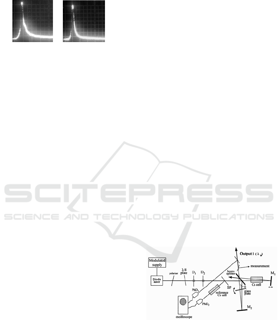
Figure 16. Typical oscilloscope traces (5 ns/div) of the
optimized selected spike: left – for the known technique
of competitive resonators and right- for our proposed
AMIR- approach. Full confirmation of improvement of
the selection by our predicted theoretical approach.
The generated sub-nanosecond pulses are of interest
for testing system in optical communications, in
systems for distance measurements, in scientific
works and in remote sensing.
3 DEVELOPMENT OF LASERS
WITH FIXED EMISSION
FREQUENCY AT REFERENCE
ATOMIC ABSORPTION LINE
A simple, all-optical technique for producing pulsed
semiconductor laser light, spectrally narrowed and
fixed at a chosen absorption atomic line, is realized
and studied by us [Deneva, 2010]. The technique,
which is not of laser locking type, is based on
utilization of a conventional diode laser without any
impact on its operation. For its implementation the
diode laser output is fed to a modified Michelson
interferometer, and controllable disturbing of phase
and amplitude correlation between the interfering
beams in the two arms of the interferometer is
achieved by frequency scanning through a contour
of reference absorption line of substance, introduced
in one of the interferometer arms. Imbalance is
produced by the absorption and the refractive index
changes throughout the contour of the absorption
line. The control of the imbalance is realized by
variation of the optical path length of the other arm
of the interferometer through an appropriate tilting
of a glass plate introduced in this arm.
We have shown both by theory and experiment
that under properly chosen conditions the spectrum
of the obtained light partially overlaps the atomic
line and has linewidth, comparable to the width of
the absorption transition.
The set-up is given in Figure 16. A commercial
single longitudinal mode pulsed diode laser (DBR
type, model SDL-5702-H1) with emission line width
of about 100 MHz was used as a light source. The
wavelength of the selected mode of the diode laser
was repetitively scanned (forward -backward) within
± 10 GHz (~ 0.0210 nm) around the 852.1 nm Cs
absorption line (6S
-6P
1/2 3/2
transition - a single
absorption line within the scanned frequency region.
The scanning was accomplished by the pump current
modulation within ± 5 mA around 44.3 mA. The
line width of the chosen Cs-transition was ≈
0.92 GHz (0.0019 nm, FWHM). The diode
temperature was kept at 17.9
o
C with accuracy of
±0.1
o
C. The diode laser beam, after passing through
an optical isolation system (Faraday Isolator or a
combination of a polarizer and a quarter-wave plate,
as shown in Figure 16), impinged the entrance
beam-splitter of a modified Michelson
interferometer composed of the beam-splitter and
wedged full reflecting dielectric mirrors M
and M
1 2
.
The beams reflected from M
and M
1 2
interfered at
the beam splitter and formed the useful
interferometer output (Output 1 in Figure 17).
A cell with atomic Cs vapour at room
temperature (22
o
C) was introduced to assure
reference line in the first interferometer’s arm
between the beam-splitter and the mirror M
1
(at
852.1 nm Cs line).
If the wavelength of the selected mode remained
outside the absorption line during the scanning of
the diode driving current, the interference conditions
did not change, and the Output 1 did not exist.
Figure 18 shows the signals from the diodes PhD
1
and PhD
2
; curve A corresponds to the Michelson
interferometer Output 1 whereas the curve B depicts
the signal from the diode PhD
2
(inverse polarity)
that gives the absorption by the Cs line in the
external reference Cs cell.
Figure 17. Experimental set-up for producing diode laser
light spectrally fixed at the Cs absorption line.
When the laser diode wavelength fell into the
contour of the chosen absorption line, the variation
of the refractive index and the absorption changed
the interference conditions. Thus the destructive
interference was terminated and interferometer
Output 1 appeared.
First International Conference on Telecommunications and Remote Sensing
154
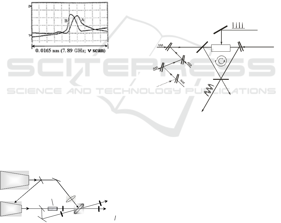
For the optimized conditions (Figure 18(c)),
achieved by appropriate declination of the glass
plate), the locked line is practically a single line with
line width (~1.7 GHz, or 0.0035 nm) that is
comparable to the absorption line width (0.9 GHz,
0.0019 nm) and overlaps the absorption by
approximately 45%. The Output 1 is ~ 2 mW for
~10 mW laser diode emitted power. The
performance is completely reproducible (~ hours).
The theory is in satisfactory agreement with the
experiment and confirms the possibility of such kind
of diode laser light generation.
The reported technique can be useful in a variety
of spectroscopic applications when the target is a
single transition which should be excited to monitor
or separate a particular substance from a mixture of
different substances.
Figure 18. Spectrograms of the laser diode light emitted
from Output 1 (curve A) and of the reference Cs cell
(curve B; inverted signal). The exciting current is scanned.
Another simple system of spectral locking of the
laser emission at the reference absorption line is also
developed [Deneva, 2005; Gacheva, 2008]. Its
principle is based on the disturbance of the
competition between two injection-controlled
generations in a two-channel resonator or two
amplifications in single active medium. The injected
light before the injection in one of the cannels or the
amplifier input passes through a substance with the
desired absorption line. This solution is clarified
from the applied Figure 19.
Figure 19. Frequency locking set-up.
The principle of our injection-locking technique
is theoretically and experimentally demonstrated in
our previous works [Keller, 2000; Slavov, 1998].
4 PRINCIPLE OF NEW
INJECTION-LOCKING
LINEAR AMPLIFIER OF
AMPLITUDE MODULATED
LASER LIGHT
At this point, we describe our principle of new
injection-locking amplifier of amplitude modulated
laser light using counter injection in a ring laser
configuration. The last development includes the
multichannel information laser light amplification
(of the order of ~ 10
6
and more – from µW to W)
with high linearity of the amplification. To amplify
the injected in ring laser modulated laser light
(simplest practical arrangement of the amplifier) we
introduce counter-injection that compete with the
modulated light and compel the amplification to
follow exactly the modulation. The principle is clear
from Figure 20 [Deneva, 1999].
λ
1
?
3
?
2
?
4
Pump
?
1
.
.
.
i
?
M
3
M
1
M
2
active
medium
IW
ccw
cw
output cw
amplified (x10 ) light
6
output ccw
CW counterinjection
at (~1mW)?
c
injected beam
??
1...i
(~W)µ
?i
IW
IW
IW
λ
1
… λ
i
(μW)
λ
c
(~ 1mW)
λ
1
…
λ
i
λ
λ
λ
λ
IW
λ
1
?
3
?
2
?
4
Pump
?
1
.
.
.
i
?
M
3
M
1
M
2
active
medium
IW
ccw
cw
output cw
amplified (x10 ) light
6
output ccw
CW counterinjection
at (~1mW)?
c
injected beam
??
1...i
(~W)µ
?i
IW
IW
IW
λ
1
… λ
i
(μW)
λ
c
(~ 1mW)
λ
1
…
λ
i
λ
λ
λ
λ
IW
Figure 20. A new system for linear amplification based on
injection–locking technique with counter- injection for
linearization of the amplification (possibility – kW output
power, ~ 10
6
- 10
7
gain for injected modulated light of
power ~ mW and μW)
We describe the action of the new ring counter-
injection amplifier for the case of multichannel (at 5
wavelength channels) modulated laser beam
amplification by adapting the rate of differential
equations, adding the members that describe
modulated injection and counter-injection.
Figure 21 gives typical calculation for single
sine modulated wave. We have shown the ability of
our amplifier to amplify simultaneously and linearly
a number of injected beams with different frequency
in a large range of ~ 800 GHz. The nonlinear
distortions, defined by the harmonics relative power
are less than 1 %. Such amplification is possible in
very wide range of ~ 2400 GHz. The calculated
Injecting
laser
Pumping
laser
active
medium
absorption
medium at
λ
a
M
4
M
2
p
u
m
P
M
beam
splitter
beam
splitter
Injecting
laser
Pumping
laser
M
1
3
M
3
4
2
p
u
m
P
output
only at
λ
=
λ
a
λλ
a
M
output
at
λ
=
λ
a
λ
=
λ
a
beam
splitter
Injecting
laser
Pumping
laser
active
medium
absorption
medium at
λ
a
absorption
medium at
λ
a
λ
a
M
4
M
2
p
u
m
P
M
beam
splitter
beam
splitter
Injecting
laser
Pumping
laser
M
1
M
1
3
M
33
M
3
4
2
p
u
m
P
output
only at
λ
=
λ
a
λλ
a
output
only at
λ
=
λ
a
λλ
a
M
output
at
λ
=
λ
a
λ
=
λ
a
beam
splitter
output
at
λ
=
λ
a
λ
=
λ
a
Development of Original Optical and Quantum Electronics Devices for Applications in Communications,
Metrology and Sciences
155
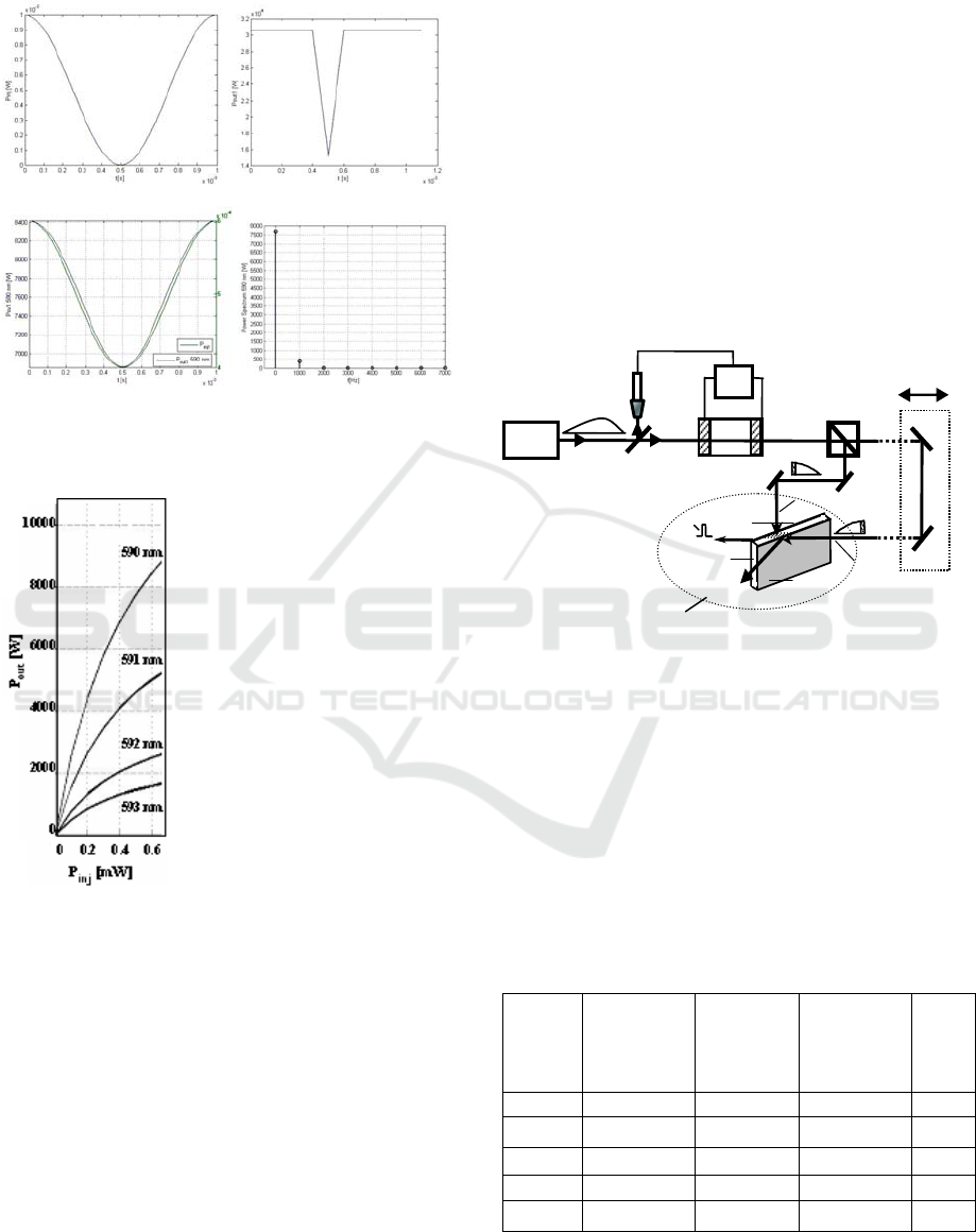
curves of amplification for 4 wavelengths
(communication channels) are shown in Figure 22.
(a) (b)
(c) (d)
Figure 21. Example of operation of our ring-amplifier. (a)
input signal, (b) and (c) – amplification without and with
counter-injection, (d) Fourier spectrum of the (c).
Figure. 22. The curves of
simultaneous amplification of 4
injected lines in the presence of
counter-injection (~1mW). It
can be seen that the
amplification is practically
linear for injected power
variation between 0.01mW and
~ 0.3mW. The amplification
factor is ~ 10
5
.
5 DEVELOPMENT OF OPTICAL
TRANSISTOR
The new interferometer type device for light control
by light (DLCL) uses on one hand the high
sensitivity of the Fabry-Perot Interferometer (FPI) or
IW to the losses in the interferometer’s gap [Deneva,
2004]. Our original idea is to use the possibility to
illuminate chosen volumes of the edge of
interferometer’s or wedge’s gap in two quite
different manners: i) through the interferometer
mirrors (beam A- as shown in the figure); ii) directly
into the gap (beam B). If the gap is full with
saturable absorption medium and the mirrors are
high reflective – e.g. 0.92–0.99, the beam A will
affect the saturable absorber transmission only by
transmitted small part through the mirror and
respectively the FPI transmission will be drastically
low for this beam. When the beam B illuminates
directly the saturable absorber the effect of this
illumination is very strong (no decreasing the
illuminated light intensity by the mirror). Thus, with
the low power beam B we can control in efficient
manner (or to open and stop) the FPI or IW
transmissivity for beam A. One first application of
the new optical transistor will be to forms rectangular
nano- and sub-nanosecond pulses as it can be
understand from the Figure 23.
BS
OS
PC
GP
M
1
M
2
M
3
M
4
PP
A
PP
B
OP
IP
OR
Nd:YA
laser
Cr
4
+
:YAG
(IFP plate)
IFP mirror
IFP
beam B
beam A
S
Figure 23. Schematic diagram of a Cr
4+
:YAG- DCLC and
of the experimental set-up for forming controlled duration
rectangular laser light pulse. OR – optical receiver-
synchronizer, PC-Pockel’s cell, GP-Glan Prism, M
,M
1 2
-
high reflectivity mirrors. The high speed switching PC
(~ 1-2 ns), activated near the maximum of the input ~ 30
ns pulse, switches the polarization and the GP forms two
spatially separated pulses that act in the described manner
upon the Cr
4+
gap FPI or IW.
Table 1: Example of transmissivity of new DLCL for
Cr
4+
:YAG as a saturable absorber [Nenchev, 2011]. The
parameters of the DLCL are given in the table.
R of the
mirrors
IFP or IW
Thickness, mm
Illuminating
beam energy
density
J/cm
2
Controlling
beam energy
dens. J/cm
2
T
%
0.99
0.4 0.5 (0.5) 0 (0.1|) 3(8.6)
0.99
0.2 0.5 (0.5) 0 (0.1| 3( 21)
0..99
0.1 0.5 (0.5) 0 (0.1) 9(40)
0.92
2.65 0.5 (0.5) 0 (0.1) 9(40)
0..52
20 0.5 (0.5) 0 (0.1) 1(10)
First International Conference on Telecommunications and Remote Sensing
156

ACKNOWLEDGEMENTS
The authors thank to our colleagues from University
CNAM-Paris, University of North Paris, University
“Sent Quentin” – Versailles and the University of
South Paris, France for fruitful collaboration. We
thank also to National Science Fund and Technical
University of Sofia, Division R&D for the financial
support, Contract D-RILA 01/7-19/13.12.2011
(
Pr. 25197 VB).
REFERENCES
(Principal authors’ articles, used in the presentation; the
used non-authors’ articles are cited therein)
Stoykova E., Nenchev M., 2010. Gaussian Beam
Interaction with Air-gap Fizeau. Journal of the Optical
Sociaty of America–JOSA A, Vol.27, 58–68.
Deneva M., Stoykova E., Nenchev M., Barbe R., Keller
J.C., 2010. Diode laser emission, spectrally fixed at
atomic absorption line, Optics&Laser Technology,
Vol.42, 301-307.
Deneva M., Uzunova P., Nenchev M., 2007. Tunable
subnanosecond laser pulse operation using an active
mirror concept, Opt. Quant. Electron., Vol.39, 93-212.
Louyer Y., Wallerand J., Himbert M., Deneva M.,
Nenchev M., Two-wavelength passive self-injection
controlled operation of diode-dumped cw Yb-doped
crystal lasers, 2003, Appl.Opt., Vol. 42, 4301-4315.
Slavov D., Nenchev M., 2001. A comparative study of
approaches for spectral control of Ti:Sapphire lasers.
Optics Communications, Vol.200/1-6, 283-301.
Delev A., Deneva M., Nenchev M., Stoykova E., Slavov
D., 2001. Tunable subnanosecond pulse generation in
a dye laser using overlapped pump pulses. Rev. Sci.
Instrum., Vol.72, N°3, 164- 168, USA
Keller J.C., Barbe R., Deneva M., Nenchev M., 2000.
Unidirectional ring Ti
3+
:Sapphire
laser generation at
the wavelength of an atomic absorption line by
bidirectional passive self-injection locking. Applied
Phys. Letters, 76, 131-133.
Nenchev M., 1978. Multicolor laser, Bul.pat. IIR,
No25954 (Bulgaria).
Slavov D., Deneva M., Stoykova E., Nenchev M., Barbe
R., Keller J.C., 1998. Output control of a ring laser
using bi-directional injection: a new approach for
unidirectional generation at a reference atomic
absorption line. Optics Communications.157,343 -351.
Stoykova E., Nenchev M., 2001. Strong optical
asymmetry of an interference wedge with unequal
reflectivity mirror and its use in unidirectional ring
laser oscillator-amplifier system. Applied Optics, 40,
5402-5412.
Nenchev M., 1981. Tunable two-wavelength laser, Bulg. Pat.
No 32703 (Bulgaria); Nenchev M., 1986. Two wavelength
laser oscillator, Bulg. Paent,. No73793 (Bulgaria)
Stoykova E., Nenchev M., 1996. Reflection and
transmission of unequal mirrors interference wedge,
Opt. Quantum. Electron. 27, 155-167.
Deneva M., Stoykova E., Nenchev M., 1996. A novel
technique for a narrow-line selection and wideband
tuning of Ti
3+
:Sapphire and dye lasers, Rev. Sci.
Instrum. 1705-1714.
Gorris-Neveux M., Nenchev M., Barbe R., Keller J.C.,
1995. A two-wavelength, passively self-injection
locked, cw Ti
3+
:Sapphire
laser. IEEE J. Quantum
Electron. 31, 1263-1260.
Nenchev M., Stoykova E., 1993. Interference wedge
properties relevant to laser applications: transmission
and reflection of the restricted light beams, Opt.
Quantum Electron. 26, 789-799.
Stoykova E., Nenchev M., 1994. Strong optical
asymmetry of an interference wedge with unequal
mirrors and its use in unidirectional ring laser designs.
Opt Lett. 19, 1925-1927.
Meyer Y., Nenchev M., 1984. Optical Selector Devices Using a
Fizeu Wedge for Reflection. US Patent No4, 468, 775, USA
Deneva M., Nenchev M., 2004. Development and
application of a new device for light control by light
(optical transistor). “Electronics-ET’04, International
Conference, book 1, 181-185, ISBN 954-438-445-6,
Bulgaria.
Nenchev M., 1995. Device for forming of laser pulse,
Bul.pat. IIR,No49797 (Bulgaria).
Nenchev M. N., Meyer Y.H., Continuous Scanning
System for Single-Mode Wedge Dye Lasers, 1982.
Opt Lett. 7, 199-200.
Gizrekht A., Kebedjiev A., Nenchev M., Peshev Z.,
Pestriakov E., 1989. Two wavelength emission from
Ti
3+
:Sapphire
crystal laser. Sov. J. Quant. Electron.,19,
1305-1306.
Deneva M., Nenchev M., 2005. Development of original
simple quantum electronic devices with emission
passively frequency locked at atomic absorption line.
“Electronics-ET’05”, International Conference, 186-
193, Book 2, ISBN 954438185, Bulgaria; Method and
device for laser pulse shortening, Bulg. Patent No
35164/1995, Bulgaria.
Gacheva L., Deneva M., Kalbanov M., Nenchev M., 2008.
Development of original all-optical injection control
competition and gain knock-down technique for laser
line fixing at atomic absorption line. Inern. Confer.
“Electronics ET’2008”. 135-142, Bulgaria.
Deneva M., Nenchev M., 1999. Injection-locked linear
amplifiers of a periodically modulated linear radiation
using competitive second injection. LTL Plovdiv’99,
International Symposium, 87-94, Bulgaria.
Nenchev M., Deneva M., Recent results in the
development of original quantum electronics and
optical devices for applictions in communictions and
metrology, J. Technical University of Plovdiv, 2011.
Vol.16, book 1, 27-42, Bulgaria.
Svelto O., Principle of lasers, 1998. Plenum, New York,
4-th edn.
Development of Original Optical and Quantum Electronics Devices for Applications in Communications,
Metrology and Sciences
157
