
Pose Estimation using a Hierarchical 3D Representation of Contours and
Surfaces
Anders Glent Buch
1
, Dirk Kraft
1
, Joni-Kristian K
¨
am
¨
ar
¨
ainen
2
and Norbert Kr
¨
uger
1
1
Maersk Mc-Kinney Moller Institute, University of Southern Denmark, Odense, Denmark
2
Tampere University of Technology, Tampere, Finland
Keywords:
Pose Estimation, Shape Context Descriptors, Early Cognitive Vision.
Abstract:
We present a system for detecting the pose of rigid objects using texture and contour information. From
a stereo image view of a scene, a sparse hierarchical scene representation is reconstructed using an early
cognitive vision system. We define an object model in terms of a simple context descriptor of the contour
and texture features to provide a sparse, yet descriptive object representation. Using our descriptors, we do
a search in the correspondence space to perform outlier removal and compute the object pose. We perform
an extensive evaluation of our approach with stereo images of a variety of real-world objects rendered in a
controlled virtual environment. Our experiments show the complementary role of 3D texture and contour
information allowing for pose estimation with high robustness and accuracy.
1 INTRODUCTION
The pose estimation problem is a crucial aspect in
many vision, robotic and cognition tasks. Many sys-
tems solve the problem of obtaining the location of
the object of interest by tailoring the implementa-
tion to a specific object class or by relying on a spe-
cific feature type. Many 2D or image-based meth-
ods (Bay et al., 2006; Belongie et al., 2002; Lowe,
1999; Payet and Todorovic, 2011) learn an object
model by discretizing over the set of possible views
on an object, and base the detection on this represen-
tation. In 3D methods (Bariya and Nishino, 2010;
Drost et al., 2010; Hetzel et al., 2001; Johnson and
Hebert, 1999; Novatnack and Nishino, 2008; Papa-
zov and Burschka, 2010; Rusu et al., 2009; Stein and
Medioni, 1992; Wahl et al., 2003), there is a tendency
towards the use of range data which provides a large
set of surface points in the scene. Correspondences
between these points and a 3D model are then sought,
from which a pose is calculated.
We address the problem of estimating the pose of
rigid objects with known geometry and appearance
based on calibrated stereo image views of the ob-
ject. From the input stereo image, we reconstruct a
3D scene representation using an early cognitive vi-
sion system (Jensen et al., 2010; Pugeault et al., 2010)
covering contour and surface information.
Based on our features, we define relations be-
tween feature pairs. These relations encapsulate both
appearance and shape information. Inspired by (Be-
longie et al., 2002), we call the total set of relations
for a feature in a given spatial region a context. The
feature context descriptor is used for discriminative
correspondence search during pose estimation.
In Figure 1, we show the effect of combining both
contour points (blue) and surface points (red) in the
estimation process from a training view (top). Even
though contour information is adequate for obtaining
an alignment, it is clear that the quality of the fit is
poor, which can be easily seen by the misaligned edge
contours which should be on the corner of the object.
In summary, the work described in this article
makes two main contributions:
1. The potential of using viewpoint invariant 3D re-
lations for pose estimation and
2. By combining different 3D entities, i.e. contour
and surface information, higher precision and ro-
bustness in pose estimates can be achieved.
The paper is structured as follows. In Sect. 2 we
describe the feature extraction process. In Sect. 3,
we describe how the object representation is obtained.
Sect. 4 describes how model-scene correspondences
are obtained, and Sect. 5 how the estimation process
is performed. Finally, experiments provide an evalua-
tion of our process in Sects. 6 and 7.
105
Glent Buch A., Kraft D., Kämäräinen J. and Krüger N..
Pose Estimation using a Hierarchical 3D Representation of Contours and Surfaces.
DOI: 10.5220/0004275801050111
In Proceedings of the International Conference on Computer Vision Theory and Applications (VISAPP-2013), pages 105-111
ISBN: 978-989-8565-47-1
Copyright
c
2013 SCITEPRESS (Science and Technology Publications, Lda.)

Figure 1: Pose estimates using contour features only, sur-
face features only and the combination of both. Top: a
frontal training stereo view used for generating a model.
The input view (bottom) is rotated 35
◦
compared to the
training view. The trained model points are shown in blue
(contours) and red (surflings). White points represent the
matched points in the input. The error is given as the ground
truth translation error. Left: Fit using only contours. Mid-
dle: Fit using only surfaces. Right: Fit using both kinds of
features.
1.1 Related Work
In the domain of 3D object alignment, a significant
amount of research has been done. Methods based on
local descriptors have proven to be usable in resolving
correspondences between a stored model and a scene
in a stable manner. Many of these works involve 2D
descriptors (see e.g. (Bay et al., 2006; Belongie et al.,
2002; Lowe, 1999)). Since these methods do not need
any kind of 3D data, they can be directly applied to
monocular images. In general, for these methods the
accuracy of the pose estimate is limited since rather
significant pose changes in 3D might result in only
small changes in the projected image.
A notable work using 3D entities is (Johnson and
Hebert, 1999) where descriptors are formed as spin
images which act essentially as a sub-sampling of the
shape information in the neighborhood of a surface
point. In a previous work (Stein and Medioni, 1992),
a splash descriptor is formed by the differential prop-
erties of the neighborhood. An interesting descrip-
tor is presented in (Bariya and Nishino, 2010; Novat-
nack and Nishino, 2008) where focus lies on scale-
dependent keypoint features providing rich shape in-
formation. In (Hetzel et al., 2001; Rusu et al., 2009),
local geometric descriptors are formed by histograms
of relative coordinate frames for capturing local char-
acteristics of the object. Some of the most convincing
results, however, have been reported based on very
local point pair representations (Drost et al., 2010;
Papazov and Burschka, 2010; Wahl et al., 2003) in
which the density of the full model representation is
utilized. In (Payet and Todorovic, 2011), contours are
used in a framework for monocular-based object de-
tection. Instead of a context descriptor, a summary
descriptor is generated on a lattice in the image.
All the methods mentioned above operate on geo-
metric information only on one scale and one kind of
descriptor without making use of any relational infor-
mation in 3D. In our approach we make use of the
different granularities in the visual hierarchy, show
the complementary role of surface and contour infor-
mation and apply viewpoint invariant relational fea-
ture descriptors. In addition, our method includes
appearance information by incorporating appropriate
descriptors.
The concept of using context information derives
from (Belongie et al., 2002; Frome et al., 2004) in
which such context information is encoded by defin-
ing a 2D or 3D neighborhood around a point. The
difference to our approach is that the distal properties
encoded are not restricted to the spatial domain but
also apply to appearance attributes, and that we op-
erate on two kinds of descriptors at the same time on
different levels of granularity.
2 ECV SCENE
REPRESENTATION
The foundation of our work lies in the way 3D entities
are obtained given a stereo image pair. We make use
of an early cognitive vision (ECV) system described
in (Jensen et al., 2010; Pugeault et al., 2010), which
provides a processing hierarchy from the lowest level
(pixels) to increasingly higher level of abstraction (see
Figure 2).
The system first performs linear image filtering
operations for the extraction of 2D primitives, here
line segments and textured regions (texlets). Cor-
respondences between left and right image are then
searched for, and the line segments and texlets are re-
constructed in 3D. The result of this is a relatively
dense 3D scene representation in both the contour
and the surface domain containing line segments and
texlets. We refer to these entities as primitives. The
line segments are defined by position, direction and
color, and texlets by a position, normal vector and
mean color. These 3D primitives can be grouped,
which results in higher-level entities, or simply fea-
tures, which we call contours and surflings. A contour
thus consists of a set of line segments with similar di-
VISAPP2013-InternationalConferenceonComputerVisionTheoryandApplications
106

Figure 2: Example of an ECV interpretation of a scene.
rection and color. Similarly, a surfling is made up of a
group of texlets with similar normal vector direction
and color. The grouping has a smoothing effect which
increases robustness of the generated features, even
under large viewpoint transformations. The ECV rep-
resentation of an example scene is shown in Figure 2.
3 ECV CONTEXT DESCRIPTORS
The result of the ECV processing presented in Sect. 2
is a scene representation consisting of a sparse set of
features with a high descriptive ability. These features
capture the object geometry and appearance in differ-
ent ways. Contours reflect distance and orientation
discontinuities as well as color borders. Surflings are
able to describe the local appearance of a surface. At
the current stage, we generate a training stereo image
based on a textured CAD model from which we ex-
tract the 3D feature set. This process could also be
done using views of real objects captured in an exper-
iment setup.
To obtain an even higher level of descriptive abil-
ity, we calculate relations between a feature and all
other features in a local spatial region. Inspired by
(Belongie et al., 2002; Frome et al., 2004), we refer
to the complete set of relations of a given feature as
a context. An object model thus consists of a set of
features and their contexts. The locality of a context
is controlled by a radius given as a distance in Eu-
clidean space. In contrast to many existing methods,
our context descriptors also include appearance infor-
mation. Figure 3 shows the whole processing pipeline
from input image to 2D primitives to 3D features (left
part), and finally to the context of a feature using a
Figure 3: ECV representation of the KIT object “Blue-
SaltCube” and an example of a surfling context descriptor.
Top part: left input image from rendered stereo image, ex-
tracted 2D primitives (line segments and texlets) and recon-
structed 3D contours and surflings (contours not shown by
intrinsic color, but using a unique color label). Bottom part:
an example context based on set of relations of a surfling
with a radius of 25 mm. Relation parameter distributions
shown by histograms.
radius of 25 mm (right part). The five histograms of
the context descriptor show the sampled distribution
of the relations to the neighboring features in terms of
geometry (angle and distance) as well as appearance
(RGB color differences). The object is taken from the
Karlsruhe Institute of Technology (KIT) database of
household objects (KIT, ), which is also used for the
experiments presented in Sect. 6.
As previously mentioned, we extract context in-
formation both in the model building phase as well
as in the execution phase. As the features represent
different visual modalities (Kr
¨
uger et al., 2004), the
parametrization also differs. We list the relational fea-
ture parameters in Table 1. Contours are denoted by
C and surflings by S.
Table 1: Parameters of the different relation types for con-
tours C and surflings S.
Name Relation types Parameters
Angle C ↔ C, S ↔ S R
A
Distance C ↔ C, C ↔ S, S ↔ S R
D
Color difference C ↔ C, C ↔ S, S ↔ S R
~c
Distances are calculated using the center points of
the features. For surflings, the angle is simply de-
PoseEstimationusingaHierarchical3DRepresentationofContoursandSurfaces
107

fined as the dihedral angle. For contours, we perform
a principal component analysis on the contour line
segments and take the eigenvector corresponding to
the largest eigenvalue to get the main direction. This
direction vector is then used for calculating angle dif-
ferences. In Figure 4, we show how these spatial re-
lations are obtained.
Figure 4: Spatial relations for a contour pair (left) and a sur-
fling pair (right). This figure also shows the line segments
making up a contour as well as the texlets making up a sur-
fling.
The context descriptor D of a feature F ∈ {C, S}
is defined as the complete set of feature relations R ∈
{R
A
,R
D
,R
c
} in a neighborhood bounded by the radius
r.
D(F ) = {R (F ,F
0
) | R
D
(F ,F
0
) < r} (1)
where F
0
is any other feature in the neighborhood. A
complete object/scene model, M and S , is thus ex-
tracted from the total set of descriptors, which we de-
note as:
M = {D
M
} (2)
S = {D
S
} (3)
4 CORRESPONDENCES
We perform a correspondence search between the
model M and the scene descriptors S in order to
eliminate scene features not expected to be part of
the model sought. This operation can be regarded
as a filtering which removes scene entities which do
not match the model features according to some met-
ric. This metric is defined in Sect. 4.1 where we ex-
plain the feature matching. In Sects. 4.2 and 4.3, we
show how this information is used for resolving cor-
respondences. While the correspondence matching in
Sect. 4.1 is done on entities extracted on higher lev-
els of the visual hierarchy (i.e. contours and surflings)
and their contexts, the actual computation of the pose
is done based on the local primitives which the higher
level entities consist of (i.e. 3D line segments and
texlets). Sect. 5 describes how the final pose estima-
tion is done based on the remaining set of putative
feature correspondences between the model and the
scene.
4.1 Matching
For the relations in Table 1, we define a discrete func-
tion ξ ∈ {C ↔ C,C ↔ S, S ↔ S} for a given relation
R which enumerates the possible combinations of en-
tity pairs or relation types. This is done to assure that
only alike relations are compared. It would not make
sense to match e.g. a relation of type C ↔ C against a
relation of type C ↔ S.
Given the context descriptors of two features of
the same type, we perform matching using the follow-
ing cost function based on mean absolute differences:
c(D
M
,D
S
) =
1
|
D
M
|
∑
R
M
∈D
M
min
{R
S
∈D
S
: ξ(R
M
)=ξ(R
S
)}
abs(R
M
− R
S
)
|
R
M
|
(4)
where | ·| denotes the cardinality of a set. The term in-
side the sum calculates for each relation in the model
descriptor the “distance” to the nearest matching rela-
tion in the scene descriptor. This can also be regarded
as a local assignment using closest point matching
measured by absolute differences. Since the differ-
ent parameters have different ranges, we normalize
all parameters and thereby the cost c to the interval
[0,1]. Fortunately, all parameters except distances are
intrinsically bounded (e.g. angles are bounded to the
range [0, 90]
◦
). For the distance parameter, we simply
normalize using r since this represents the maximally
possible distance deviation between two relations.
4.2 Feature Assignment
To establish correspondences between a model and a
scene, we calculate all descriptors D
S
of the scene and
compare them to the model descriptors D
M
using (4).
We form an unbalanced weighted bipartite graph G =
(U,V,E) where
|
U
|
=
M
,
|
V
|
=
|
S
|
. Each edge is
labeled by c(D
M
,D
S
). Clearly, edges can only be
drawn between features of the same type which makes
the graph incomplete.
To solve the assignment, we generate a cost ma-
trix of dimension |U | × |V | of all the edge labels. We
then apply the Hungarian method (Kuhn, 1955) which
produces a global minimum matching, i.e. a one-to-
one matching h between the model and the scene that
minimizes the following:
∑
D
M
∈M
c(D
M
,h(D
M
)) (5)
VISAPP2013-InternationalConferenceonComputerVisionTheoryandApplications
108

To remove outliers in this matching, we discard as-
signments with a cost larger than a predetermined
threshold ε
c
. The result is an injection h : M → S con-
taining putative feature correspondences for a subset
of the model features.
4.3 Point Correspondence Assignment
As will be clear from the following section, we need
3D correspondences between points in order to gen-
erate and validate pose hypotheses of the rigid ob-
ject transformation. This problem has been partially
solved by the feature assignment described in the pre-
vious section. However, taking only the center point
of the individual features provides too little informa-
tion of the object geometry for the pose estimation
step. We therefore exploit the fact that features are
the result of a grouping of lower-level point entities,
i.e. 3D line segments and texlets (see Figure 2). Since
the correspondence search relates each model feature
to one scene feature, we can transfer this knowledge
to the point entities simply by setting all points in the
corresponding scene feature as putative correspon-
dences of a point in the model feature. This choice
is based on the following observation: when a feature
assignment is performed, it is based on spatial and
appearance invariants. This does not give us any in-
formation of the absolute placement of the point enti-
ties making up the feature. Line segments and texlets
can thus float around freely under different viewing
conditions. In other words, we do not know how the
individual line segments/texlets of a contour/surfling
are ordered under different viewing conditions since
we do not know the object pose yet. We only know
that the features correspond, so all line segment/texlet
points inside a scene contour/surfling can be potential
matches of each line segment/texlet point inside the
model contour/surfling.
Based on this, we end up with a one-to-many re-
lationship between the model/scene points which we
denote P and Q respectively. The point correspon-
dences are stored as a |P |× |Q | index or match matrix
M. In the pose estimation step, we ultimately seek a
bijection between the two sets, relating each model
point to one scene point.
5 POSE ESTIMATION
The pose estimation strategy puts all the previously
mentioned methods together in a strategy for obtain-
ing an object pose from 3D scene data. The input to
the algorithm is a previously generated context model
of an object and extracted 3D features of a scene. The
following steps are performed:
1. From 3D scene feature data, extract all feature re-
lations and thereby contexts with context radius
r.
2. For all model features, match the context descrip-
tor up against each scene feature context using (4).
• If the cost c to the closest scene feature falls
below a threshold ε
c
, store the feature pair as a
putative feature correspondence.
3. Derive one to many point correspondences and
store the indexed matches in the matrix M.
• Contours: for each line segment point along
the model contour, store all line segment points
along the matched scene contour as putative
point correspondences.
• Surflings: for each texlet point on a model
surfling, store all texlet points on the matched
scene surfling as putative point correspon-
dences.
4. Find the pose estimate from the set of putative
point correspondences that gives the best fit of the
model in the scene using RANSAC (Fischler and
Bolles, 1981).
• In the sampling stage, we start by sampling
three model points randomly from P . For each
of these, we sample a correspondence from
the putative correspondence subset of Q en-
coded in the match matrix M. To obtain a
pose hypothesis, we apply Umeyama’s method
(Umeyama, 1991).
• In the verification stage, we use the median
Euclidean distance between the transformed
model and scene points to get a more robust es-
timation. This is referred to as the fit error.
This strategy assures a robust search for point corre-
spondences between the model and the scene as well
as high accuracy in the resulting pose estimate.
6 RESULTS
We have performed extensive evaluation of our algo-
rithm using the KIT database (KIT, ) which at the cur-
rent stage consists of 112 textured objects. For each
object, we generate eight 45
◦
-spaced training views of
the object to cover the whole object. Then we rotate
the object with an increment of 5
◦
away from each
training view to generate input images. We thus eval-
uate each view up against eight rotations. In Figure 5,
we show example images for five different objects.
PoseEstimationusingaHierarchical3DRepresentationofContoursandSurfaces
109
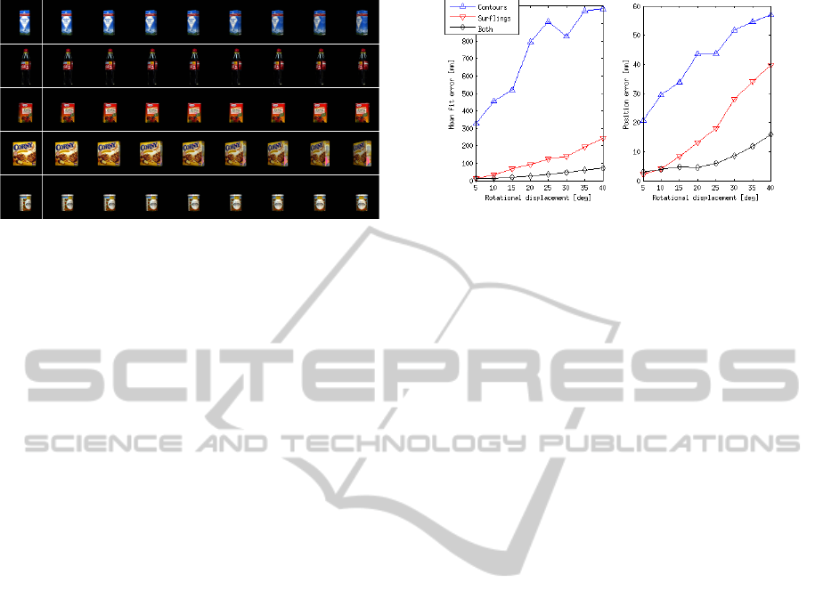
Figure 5: Example training images and test sequences (left
view only) for five different objects in the database. In the
leftmost column, the training images are shown, and on the
right side of the vertical white line, the test images corre-
sponding to the rotations {5
◦
,10
◦
,. . . , 40
◦
} away from the
training image are shown. Artifacts stem from the database
and were caused by imperfect scans.
Note that only one training case out of eight is shown
for each object.
As this is done in simulation using the textured
CAD model, we can compare our results with ground
truth and get an absolute error measure this way. An
instance of an alignment is visualized in Figure 1,
where we show these errors for contours only, sur-
flings only and both.
In the experiments we set the context radius to
r = 25 mm. This parameter should always reflect a
compromise between descriptive ability and robust-
ness towards occlusions. We have found this value to
be a good compromise. For RANSAC, we set an up-
per bound of 500 iterations. In Figure 6 we show both
the fit errors (left) and the ground truth errors (right)
of the experiments for all views of all objects.
As the ground truth errors reveal, we achieve
alignment errors well below 0.5 cm for rotation up
to 20
◦
and significantly below 2 cm even under large
rotations up to 40
◦
when combining the feature types.
Pose estimation on contours alone produces on av-
erage worse results than matching based on surface
information. However, for non-textured objects con-
taining contour information this is in general the only
information available when visual stereo is used. Pose
estimation algorithms based on texture information
only would fail completely in that case. As shown
in Figure 6, the combination of surface and con-
tour information improves performance significantly.
Hence, the experiments show that contours are an
important source of information for pose estimation,
even for textured objects.
Figure 6: Estimation results for all textured KIT objects.
Left: mean of all fit errors. Right: mean of all ground truth
errors.
7 CONCLUSIONS
We have described a pose estimation algorithm which
makes use of viewpoint invariant representations in
terms of context descriptors organized in a visual hier-
archy covering two parallel streams, one correspond-
ing to contour structures and the other to texture struc-
tures. We have made quantitative evaluations on a
data set of 112 objects for which the ground truth is
known. We have shown that the combination of con-
tour and surface information increases the accuracy of
pose estimation, keeping the ground truth error mag-
nitudes below the errors in the estimation using only
contour or surface information.
ACKNOWLEDGEMENTS
The research leading to these results has received
funding from the European Community’s Seventh
Framework Programme FP7/2007-2013 (Specific
Programme Cooperation, Theme 3, Information and
Communication Technologies) under grant agree-
ment no. 269959, IntellAct.
REFERENCES
KIT ObjectModels Web Database http://i61p109.ira.uka.de/
ObjectModelsWebUI.
Bariya, P. and Nishino, K. (2010). Scale-hierarchical 3D
object recognition in cluttered scenes. In Computer
Vision and Pattern Recognition (CVPR), 2010 IEEE
Conference on, pages 1657 –1664.
Bay, H., Tuytelaars, T., and Gool, L. V. (2006). Surf:
Speeded up robust features. In Proceedings of the
ninth European Conference on Computer Vision.
VISAPP2013-InternationalConferenceonComputerVisionTheoryandApplications
110

Belongie, S., Malik, J., and Puzicha, J. (2002). Shape
matching and object recognition using shape con-
texts. Pattern Analysis and Machine Intelligence,
IEEE Transactions on, 24(4):509 –522.
Drost, B., Ulrich, M., Navab, N., and Ilic, S. (2010). Model
globally, match locally: Efficient and robust 3D object
recognition. In Computer Vision and Pattern Recog-
nition (CVPR), 2010 IEEE Conference on, pages 998
–1005.
Fischler, M. A. and Bolles, R. C. (1981). Random sample
consensus: a paradigm for model fitting with appli-
cations to image analysis and automated cartography.
Commun. ACM, 24(6):381–395.
Frome, A., Huber, D., Kolluri, R., Bulow, T., and Malik,
J. (2004). Recognizing objects in range data using
regional point descriptors. In Proceedings of the Eu-
ropean Conference on Computer Vision (ECCV).
Hetzel, G., Leibe, B., Levi, P., and Schiele, B. (2001). 3D
object recognition from range images using local fea-
ture histograms. In Proceedings of the 2001 IEEE
Computer Society Conference on Computer Vision
and Pattern Recognition (CVPR)., volume 2, pages
394–399.
Jensen, L., Kjær-Nielsen, A., Pauwels, K., Jessen, J.,
Van Hulle, M., and Krger, N. (2010). A two-level
real-time vision machine combining coarse- and fine-
grained parallelism. Journal of Real-Time Image Pro-
cessing, 5:291–304. 10.1007/s11554-010-0159-4.
Johnson, A. and Hebert, M. (1999). Using spin im-
ages for efficient object recognition in cluttered 3D
scenes. Pattern Analysis and Machine Intelligence,
IEEE Transactions on, 21(5):433 –449.
Kr
¨
uger, N., Felsberg, M., and W
¨
org
¨
otter, F. (2004).
Processing multi-modal primitives from image se-
quences. Fourth International ICSC Symposium on
Engineering of Intelligent Systems.
Kuhn, H. W. (1955). The hungarian method for the assign-
ment problem. Naval Research Logistics Quarterly,
2(1-2):83–97.
Lowe, D. (1999). Object recognition from local scale-
invariant features. In Computer Vision, 1999. The Pro-
ceedings of the Seventh IEEE International Confer-
ence on, volume 2, pages 1150 –1157 vol.2.
Novatnack, J. and Nishino, K. (2008). Scale-
dependent/invariant local 3D shape descriptors
for fully automatic registration of multiple sets of
range images. In Proceedings of the 10th European
Conference on Computer Vision: Part III, ECCV ’08,
pages 440–453, Berlin, Heidelberg. Springer-Verlag.
Papazov, C. and Burschka, D. (2010). An efficient ransac
for 3D object recognition in noisy and occluded
scenes. In Proceedings of the 10th Asian Conference
on Computer Vision, pages 135–148. Springer-Verlag.
Payet, N. and Todorovic, S. (2011). From contours to 3D
object detection and pose estimation. In Computer Vi-
sion (ICCV), 2011 IEEE International Conference on,
pages 983 –990.
Pugeault, N., W
¨
org
¨
otter, F., and Kr
¨
uger, N. (2010). Visual
primitives: Local, condensed, and semantically rich
visual descriptors and their applications in robotics.
International Journal of Humanoid Robotics (Special
Issue on Cognitive Humanoid Vision), 7(3):379–405.
Rusu, R. B., Blodow, N., and Beetz, M. (2009). Fast point
feature histograms (FPFH) for 3D registration. In
Robotics and Automation, 2009. ICRA ’09. IEEE In-
ternational Conference on, pages 3212 –3217.
Stein, F. and Medioni, G. (1992). Structural indexing:
Efficient 3-D object recognition. Pattern Analy-
sis and Machine Intelligence, IEEE Transactions on,
14(2):125 –145.
Umeyama, S. (1991). Least-squares estimation of transfor-
mation parameters between two point patterns. Pat-
tern Analysis and Machine Intelligence, IEEE Trans-
actions on, 13(4):376 –380.
Wahl, E., Hillenbrand, U., and Hirzinger, G. (2003). Surflet-
pair-relation histograms: a statistical 3D-shape repre-
sentation for rapid classification. In 3-D Digital Imag-
ing and Modeling, 2003. 3DIM 2003. Proceedings.
Fourth International Conference on, pages 474 –481.
PoseEstimationusingaHierarchical3DRepresentationofContoursandSurfaces
111
