
Optimization of Free Viewpoint Interpolation by Applying Adaptive
Depth Plane Distributions in Plane Sweeping
A Histogram-based Approach to a Non-uniform Plane Distribution
Patrik Goorts, Steven Maesen, Maarten Dumont, Sammy Rogmans and Philippe Bekaert
Hasselt University - tUL - iMinds, Expertise Centre for Digital Media,
Wetenschapspark 2, 3590 Diepenbeek, Belgium
Keywords:
Plane Sweep, Free Viewpoint Interpolation, Cumulative Histogram, Optimization, Non-uniform Distribution.
Abstract:
In this paper, we present a system to increase performance of plane sweeping for free viewpoint interpolation.
Typical plane sweeping approaches incorporate a uniform depth plane distribution to investigate different
depth hypotheses to generate a depth map, used in novel camera viewpoint generation. When the scene
consists of a sparse number of objects, some depth hypotheses do not contain objects and can cause noise and
wasted computational power. Therefore, we propose a method to adapt the plane distribution to increase the
quality of the depth map around objects and to reduce computational power waste by reducing the number of
planes in empty spaces in the scene. First, we generate the cumulative histogram of the previous frame in a
temporal sequence of images. Next, we determine a new normalized depth for every depth plane by analyzing
the cumulative histogram. Steep sections of the cumulative histogram will result in a dense local distribution
of planes; a flat section will result in a sparse distribution. The results, performed on controlled and on real
images, demonstrate the effectiveness of the method over a uniform distribution and allows a lower number of
depth planes, and thus a more performant processing, for the same quality.
1 INTRODUCTION
View interpolation is an important technique for com-
putational video and photography,allowing the gener-
ation of novel viewpoints from a scene. A number of
real cameras are capturing a scene. Using view inter-
polation, it is possible to generate images from a non-
existing camera views using the images from the real
cameras. This can increase the user experience, for
example in sports broadcasting (Goorts et al., 2012a;
Goorts et al., 2013) and video conferencing (Dumont
et al., 2009).
View interpolation is typically achieved by using
3D reconstruction or by image-based rendering. 3D
reconstruction estimates the geometry of the scene
and can choose the novel viewpoint accordingly. The
most notable methods are visual hull (Matusik et al.,
2000; Miller et al., 2005), photo hull (Kutulakos
and Seitz, 2000) and space carving (Seitz and Dyer,
1999). While 3D reconstruction allows a large range
of novel viewpoints, the reconstruction is typically
slow and the quality is limited to the quality of the
reconstructed 3D models.
Image-based rendering, on the other hand, does
not use geometry-based models of the scene. Instead,
only the images are used to generate the novel image
directly. The most known approach is the generation
of depth maps for small baseline setups using stereo
matching (Seitz et al., 2006; Zitnick et al., 2004) and
plane sweeping (Yang et al., 2004; Dumont et al.,
2009), including depth-selective plane sweeping for
two views (Rogmans et al., 2009) or for large scenes
(Goorts et al., 2013).
In the plane sweep approach, the scene is divided
in planes, all representing a depth hypothesis. The
input cameras are projected to a plane, and backpro-
jected to the virtual image plane. By comparing the
photoconsistency of every depth plane for every pixel
of the virtual image, an optimal virtual image with a
depth map can be created. We propose a system to re-
duce the waste of computational power for the plane
sweep approach.
Typically, the planes for the depth hypotheses are
distributed evenly in the scene space, thus allocating
uniform computational power to all depth hypothe-
ses. Because the scene typically does not have a uni-
form distribution of objects, wasted performance can
be perceived by considering depth values where no
7
Goorts P., Maesen S., Dumont M., Rogmans S. and Bekaert P..
Optimization of Free Viewpoint Interpolation by Applying Adaptive Depth Plane Distributions in Plane Sweeping - A Histogram-based Approach to a
Non-uniform Plane Distribution.
DOI: 10.5220/0004524700070015
In Proceedings of the 10th International Conference on Signal Processing and Multimedia Applications and 10th International Conference on Wireless
Information Networks and Systems (SIGMAP-2013), pages 7-15
ISBN: 978-989-8565-74-7
Copyright
c
2013 SCITEPRESS (Science and Technology Publications, Lda.)
objects are present. Therefore, we present a system
where the distribution of the planes is adapted to the
scene. A histogram is calculated of the resulting depth
map to determine the plane distribution for the next
temporal frame. This will redistribute computational
power to the more dense regions of the scene, and
consequently increase the quality of the interpolation
by reducing mismatches and noise.
Multiple methods have been proposed to reduce
plane sweep complexity, reduce required computa-
tional power and increase quality. The method of
Rogmans et al. (Rogmans et al., 2009) also uses a his-
togram to select applicable depth ranges, but without
redistributing or changing the plane density. Gallup
et al. (Gallup et al., 2007) propose a histogram-based
method to determine the optimal orientation of the
planes to increase quality and reduce computational
complexity, but also without optimizing for sparse
scene regions.
The view interpolation system is achieved using
commodity GPU hardware to acquire real-time pro-
cessing. By redistributing computational power to
significant parts of the scene, less power is wasted and
more is available to other image processing stages,
such as demosaicing (Goorts et al., 2012b), segmen-
tation or depth filtering (Goorts et al., 2013).
2 VIEW INTERPOLATION USING
PLANE SWEEPING
View interpolation allows the generation of novel
views of a scene. We accomplish this by using
the well-known plane sweep approach (Yang et al.,
2003), implemented using traditional GPU paradigms
to acquire real-time processing by leveraging the pro-
jective texturing capabilities of Cg shaders. We place
a number of cameras directed at the scene and cali-
brate them to acquire the projection matrices P
i
using
the Multicamera Calibration Toolbox of Svoboda et
al. (Svoboda et al., 2005). Using those cameras, we
can construct a novel viewpoint and generate the im-
age thereof using a plane sweeping approach.
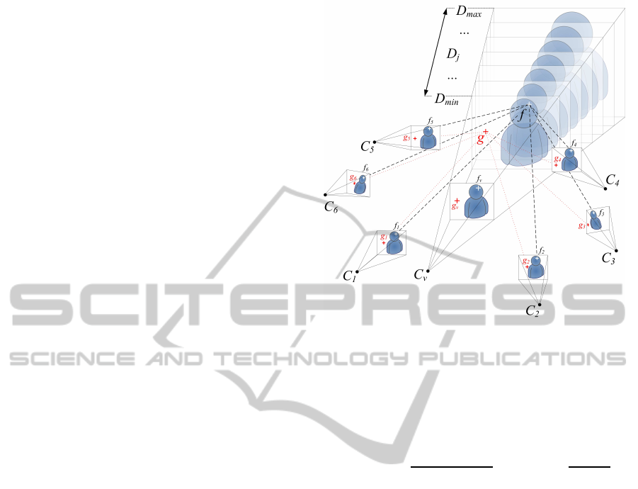
First, we divide the space in front of the virtual
camera C
v
into M planes on different depths D
i
with
D
min
≤ D
i
≤ D
max
, parallel to the image plane of the
virtual camera. Then, for every plane, we project the
input camera images C
i
to the plane, reproject them
to the image plane of the virtual camera I
v
and calcu-
late the photoconsistency of every pixel on the virtual
plane. This process is demonstrated in figure 1.
To acquire a metric for the photoconsistency, we
use a cost function, aggregated over a window to im-
prove quality. The cost function is defined as the sum
Figure 1: Plane sweeping. The space in front of the virtual
camera is divided in planes on different depths. The photo-
consistency of every pixel for every plane is considered in
the selection of the optimal depth plane, thus selecting the
optimal depth and color for the virtual image.
of squared differences (SSD):
σ(x,y) =
N
∑
i=1
kγ−C
i
(x,y)k
2
3N
with γ =
N
∑
i=1
C
i
(x,y)
N
(1)
where γ is the averageof the reprojected pixels and
C
i
is the i
th
input image of total N. The final photo-
consistency error is acquired by aggregating the SSD
for the pixels in a fixed-size window, weighted by a
(separable) Gauss filter:
ε(x,y) =
∑
u,v
w(u,v)σ(x+ u, y + v) (2)
for a window with coordinates u and v, centered at
(x,y), and Gauss weights w(u,v).
The depth plane with the lowest error value ε is
chosen, thus selecting the depth value with the highest
photoconsistency using a winner-takes-all approach.
This will result in a simultaneous generation of the
depth map and the final color, γ.
Quality is increased by using a fore-
ground/background segmentation applied to the
input images. ε(x,y) is set to infinity when the
projected pixels contains a background pixel. This
will reduce mismatches caused by noise in the back-
ground and will reduce disappearance of foreground
objects on a uniform background. This is due to the
similarity of every pixel on a uniform background,
thus obtaining a low error value ε for incorrectly
SIGMAP2013-InternationalConferenceonSignalProcessingandMultimediaApplications
8
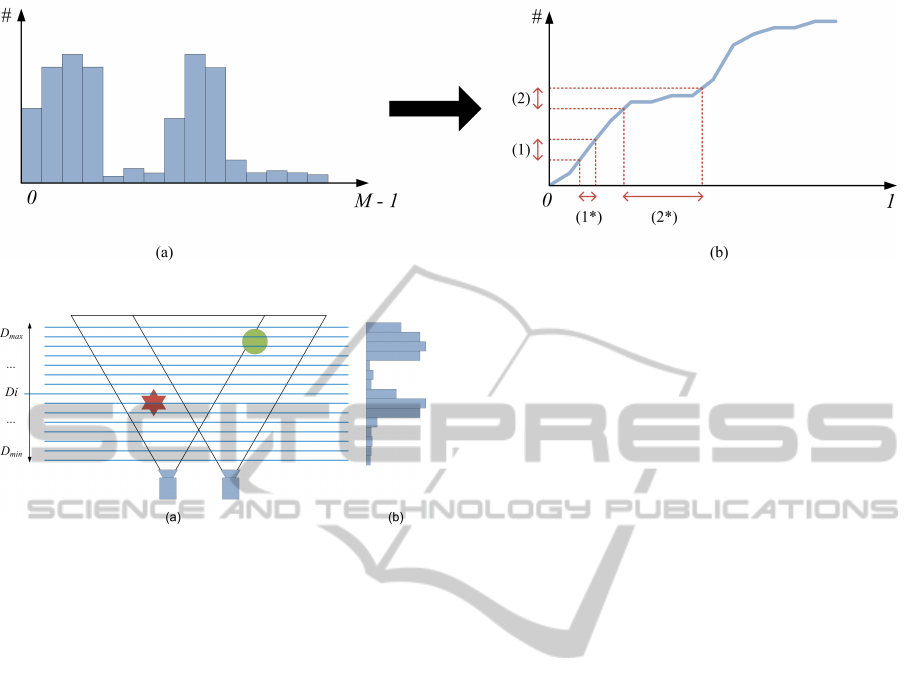
Figure 2: (a) Resulting histogram (b) Corresponding cumulative histogram H(x).
Figure 3: (a) Uniform plane distribution (b) Histogram of
the depth values.
matched background pixels. This will result in the
destruction of the foreground objects. These artifacts
are greatly reduced by processing the foreground and
the background independently.
In the traditional approach (Yang et al., 2003),
the planes are distributed uniformly in the sweeping
space. However, this will allocate computational re-
sources to depth planes where no scene information is
available. Therefore, we propose a method to reduce
wasted computational power and increase quality in
important regions of the scene.
3 ADAPTIVE NON-UNIFORM
PLANE DISTRIBUTION
When the scene consists of a limited range of depths
between D
min
and D
max
, some processing resources
are allocated to depth planes where no scene is avail-
able. This is demonstrated in figure 3(a). Here, a lot
of planes are placed in the scene where no objects are
positioned. This will waste resources and introduce
more noise due to mismatches between the cameras.
Therefore, we rearrange the distribution of the depth
planes to provide less planes in depth ranges with less
object, and more, dense planes in scene regions with
more objects. We determine the interest of a depth by
analyzing the previous frame in a temporal sequence.
The method works best when the movement of the
scene is limited, such as walking people or scenes
with many static objects.
After the interpolation step, we generate the his-
togram of the depth map using the well-known oc-
clusion querying method (Green, 2005) on GPU, al-
lowing fast processing. The histogram can be seen
in figure 3(b). The occurrence of every depth value,
as determined by thedepth of the depth planes, in
the depth map is counted. The histogram will have
discrete depth values between D
min
and D
max
, repre-
sented by the depth plane numbers, because there is
a limited number of planes. Scene depths of high in-
terest will contain more depth values than depths of
low interest. If there are depths in the scene where no
objects are present, few of this depth values will be
available in the depth map and this will be reflected
in the histogram. In the next frame, we want to pro-
vide more planes in depth ranges where a lot of depth
values can be found, thus where there are large values
in the depth histogram. The depth planes are not nec-
essary uniformly distributed, thus the histogram uses
the depth plane number as the bin value, instead of the
depth directly.
To use the depth distribution information, we con-
vert the histogram to its cumulative version, as shown
in figure 2. Here, we do not count the number of
occurrences per depth value, but we also include the
number of occurrences lower than this depth. Further-
more, we rescale the depth values from [D
min
,D
max
],
as represented by the depth plane numbers, to [0,1].
This will tranform the non-uniform distribution of the
depth planes to actual normalized depth values be-
tween 0 and 1. This transformation will generate an
increasing function H(x) = y, where x ∈ [0,1] is a nor-
malized depth value and y is the number of values in
the rescaled depth map smaller or equal to x. For val-
ues of x where there are a lot of corresponding values
in the depth map, H(x) will be steep. For values of x
with a low number of occurrences, H(x) will be flat.
Because of the non-uniform depth plane distribution
OptimizationofFreeViewpointInterpolationbyApplyingAdaptiveDepthPlaneDistributionsinPlaneSweeping-A
Histogram-basedApproachtoaNon-uniformPlaneDistribution
9
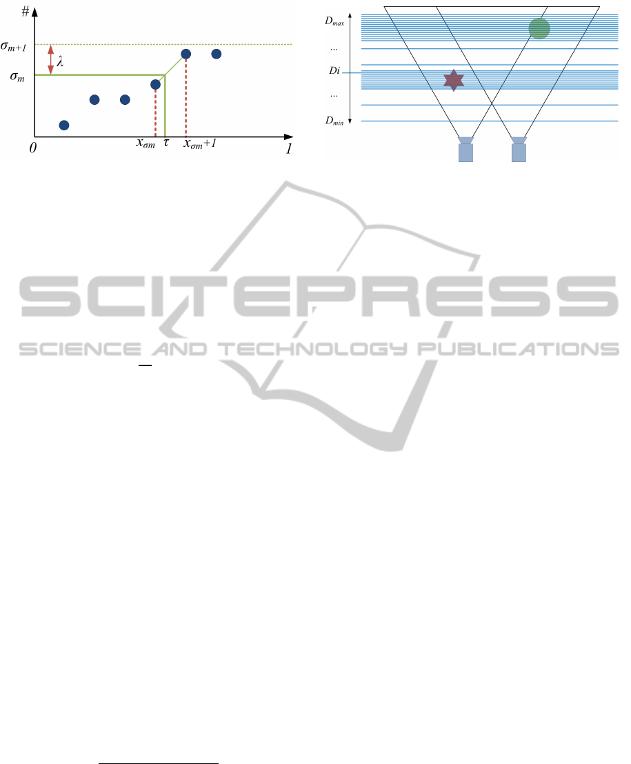
Figure 4: Detail of the cumulative histogram with discrete
values. τ is calculated by determining x
σm
and x
σm
+ 1,
such that H(x
σm
) ≤ σ
m
and H(x
σm
+ 1) > σ
m
, where σ
m
represents a depth plane number.
as input, H(x) will be constant at some points where
there were no depth planes for the corresponding nor-
malized depth value.
We will use the cumulative histogram to deter-
mine a mapping of a plane number m with 0 ≤ m < M
to a depth value D
m
with D
min
≤ D
m
≤ D
max
. For a
uniform distribution, this would be:
D
m
= D
min
+
m
M
(D
max
− D
min
) (3)
We will adapt this uniform distribution method.
When using the cumulative histogram to determine
the distribution, we calculate a fraction τ
m
∈ [0,1]
based on the plane number m, applied as follows:
D
m
= D
min
+ τ
m
(D
max
− D
min
) (4)
The fraction τ
m
is determined by the cumulative
histogram. The Y axis is divided in M cross sec-
tions, with a distance λ from each other, where λ =
max(H)/M. Each cross section represents a depth
plane m. The actual depth fraction τ
m
for each cross
section σ
m
, i.e. a depth plane, is calculated by first
determining the depth value x
σm
where H(x
σm
) ≤ σ
m
and H(x
σm
+ 1) > σ
m
. This is demonstrated in fig-
ure 4. Because the depth values x in the cumula-
tive histogram are discrete, finding a value x
σm
where
H(x
σm
) = σ
m
is unlikely, and not desirable when
generating planes that are dense, i.e. closer together,
than the depth values provided in the cumulative his-
togram.
Once x
σm
is determined, τ
m
is calculated as fol-
lows:
φ =
mλ− H(x
σm
)
H(x
σm
+ 1) − H(x
σm
)
τ
m
= φ(x
σm
+ 1) + (1− φ)(x
σm
) (5)
Figure 2(b) shows the transformation from a uni-
form depth plane distribution to a non-uniform distri-
bution based on the cumulative histogram. In point
(1), where the cumulative histogram is steep, there
Figure 5: Redistributed depth planes.
will be a dense plane distribution, as can be seen at
(1*). When the cumulative histogram is flat, a sparse
plane distribution is acquired, as can be seen at (2*).
Using τ
m
, an actual depth for every plane m (0 ≤
m < M) is determined and used in the plane sweeping
step:
D
m
= D
min
+ τ
m
(D
max
− D
min
) (6)
This can be seen in figure 5. Here, the planes are
redistributed using the cumulative histogram of figure
2(b). As can be seen, more planes are available for
determining the depth of the objects, and less planes
are available in empty space. It is desirable to include
some planes in the empty spaces between objects to
allow the appearance of objects in dynamic scenes.
To allow this, all the values in the histogram are in-
creased with a fixed number, based on the number
of pixels. This way, the cumulative histogram will
be less flat in less interesting regions, allowing some
planes here. In our tests, 0.1% of the total amount of
pixels demonstrated to be a correct value.
4 RESULTS
We tested the proposed method on different scenes
and compared image quality and planes required.
The first experiment shows the quality increase
when a low number of planes is available. To in-
crease overall quality in both methods, foreground
and backgroundsegmentation is used. Figure 6 shows
the result for a uniform depth plane distribution. Ar-
tifacts caused by the sparse plane distribution can be
clearly seen; the depth map shows clear outliers. The
depth map when using a non-uniform plane distribu-
tion, based on the histogram of the first depth map,
can be seen in figure 7. Less noise and outliers in
the depth values can be perceived. Furthermore, the
silhouette is more distinct and the features of the per-
sons are clearer. Using the non-uniform plane distri-
bution increased the quality of the depth map using a
SIGMAP2013-InternationalConferenceonSignalProcessingandMultimediaApplications
10
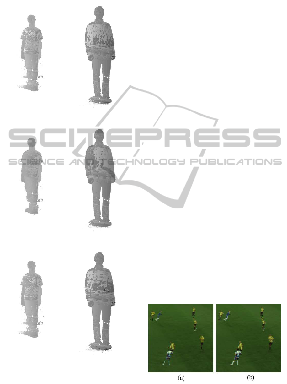
Figure 6: Depth map with a uniform depth plane distribu-
tion. A low number of planes (50) is used.
Figure 7: Depth map with a non-uniform depth plane distri-
bution. A low number of planes (50) is used.
Figure 8: Depth map with a uniform depth plane distribu-
tion. A high number of planes (256) is used.
low number of planes, thus increasing overall perfor-
mance.
Figure 8 shows the result for a high number of
planes. Here, some noise and unclear edges can be
perceived. These artifacts are effectively filtered out
using the non-uniform plane distribution. The depth
planes generating vague edges and noise are not used
and can not contribute to the depth map, and thus to
the noise and artifacts.
To demonstrate the effect of the cumulative his-
tograms, figure 10 and 11 show an input image of
a video sequence (a), the corresponding cumulative
histogram of the depth map of the preceding frame
(b) and the corresponding fraction τ from equation 5
(c). When only one dominant depth can be perceived,
such as in figure 10, one steep section in the cumula-
tive histogram is visible. This part will be transformed
to a flat value of τ, thus increasing the density of the
planes in the corresponding region in the sweeping
space. Flat sections of the cumulative histogram will
correspond to steep values in the graph of τ, resulting
in a sparse plane distribution.
When multiple dominant depths are available in
the scene, the cumulative histogram will show mul-
tiple steep sections (see figure 11). This will result
in multiple dense regions in the plane distribution, as
reflected by the values of τ in figure 11(c).
The second experiment shows the results for the
interpolation for soccer games. The video streams
used are from a live game. We placed 8 cameras at
one side of the scene and performedreal-time interpo-
lation between the cameras. To increase overall qual-
ity in both methods, foreground and background seg-
mentation is used. High-quality interpolation for soc-
cer scenes consists of different steps, apart from the
plane sweeping, such as debayering and depth filter-
ing. Therefore, the interpolation step should be as fast
as possible to reduce execution time and allow real-
time processing. By reducing the number of depth
planes, the performance can be greatly increased. By
incorporating an adaptive plane distribution system,
such as described in section 3, fewer depth planes are
required while preserving high quality.
The results can be seen in figure 13. The quality
Figure 9: Details of the quality differences between (a) fig-
ure 12 and (b) figure 13 (out method).
OptimizationofFreeViewpointInterpolationbyApplyingAdaptiveDepthPlaneDistributionsinPlaneSweeping-A
Histogram-basedApproachtoaNon-uniformPlaneDistribution
11
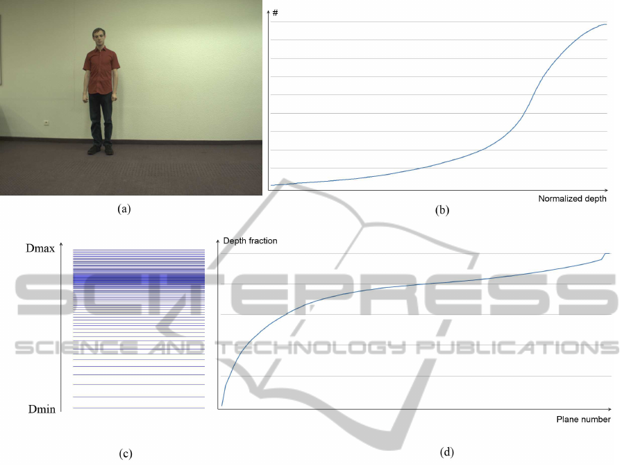
Figure 10: (a) Input image with one person. (b) Cumulative histogram of the depth map. (c) New depth plane distribution.
(d) Corresponding fraction τ for a given plane number.
is increased compared with the uniform plane distri-
bution, as seen in figure 12. Details of the quality dif-
ference can be seen in figure 9. In the uniform plane
distribution in 9(a), missing heads and limbs can be
perceived, caused by the low number of planes used
to determine the interpolated view of the players. By
redistributing the depth planes to the position of the
players, as can be seen in figure 13 an figure 9(b), ar-
tifacts are seriously reduced. The non-uniform plane
distribution method is especially applicable to soccer
scenes due to the sparse location of players on the
field and the multiple open spaces in the scene. Re-
distributing the depth planes will thus increase per-
formance by reducing the number of wasted planes.
The quality is not reduced by the movement of the
scene due to the inclusion of depth planes in empty
space. By including a few number of depth planes
in empty space, players moving in these spaces are
detected and the plane distribution is adapted accord-
ingly.
To demonstrate the high quality of our results, we
increased the number of depth planes to 5000. The
quality of the result is high, as shown in figure 14, but
real-time processing is no longer possible due to the
high computational requirements. Comparing figure
13 and figure 14, we see little difference, proving the
effectiveness of our method.
5 CONCLUSIONS
In this paper, we presented a method to reduce com-
putational requirements for view interpolation. When
the depth of the scene is not distributed evenly, the
plane sweeping method can search in depth ranges
where no objects are present, thus reducing computa-
tional power and increasing the opportunity for noise.
Our method uses the cumulative histogram of the pre-
vious temporal frame to determine a more suitable
depth plane distribution where the planes are more
dense in regions with objects and sparse in regions
with no objects. Some planes are assigned to empty
spaces to cope with dynamic scenes. All algorithms
are implemented using commodity graphics hardware
SIGMAP2013-InternationalConferenceonSignalProcessingandMultimediaApplications
12
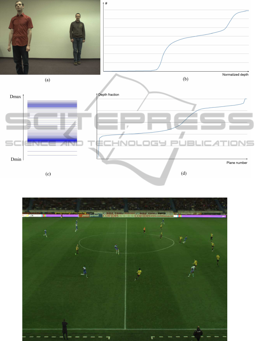
Figure 11: (a) Input image with two persons on different depths. (b) Cumulative histogram of the depth map. (c) New depth
plane distribution. (d) Corresponding fraction τ for a given plane number.
Figure 12: Plane sweeping of a soccer scene with a low number of depth planes (40) and a uniform plane distribution. Many
artifacts and missing people can be perceived.
OptimizationofFreeViewpointInterpolationbyApplyingAdaptiveDepthPlaneDistributionsinPlaneSweeping-A
Histogram-basedApproachtoaNon-uniformPlaneDistribution
13
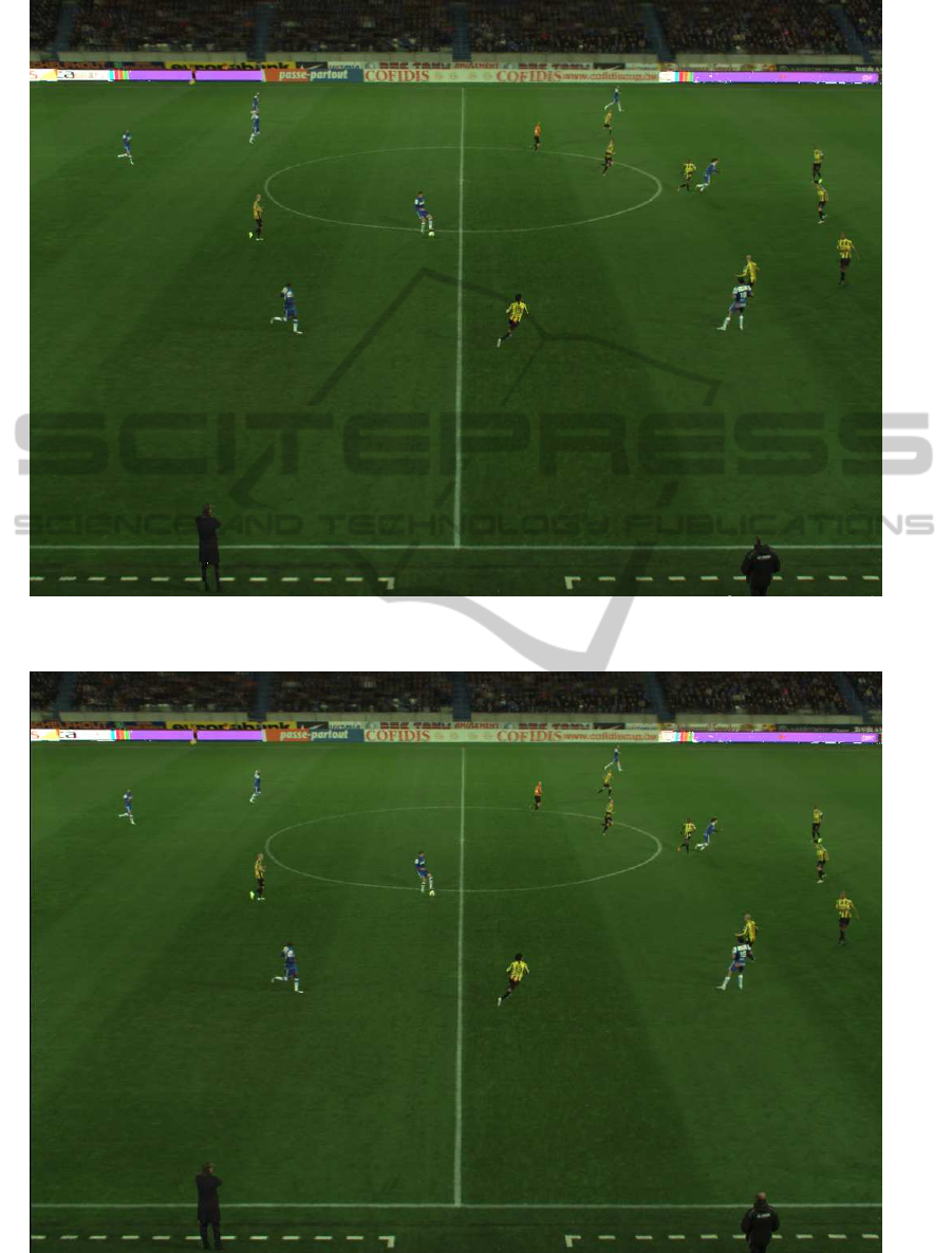
Figure 13: Plane sweeping of a soccer scene with a low number of depth planes (40) and an adaptive plane distribution. The
quality is greatly increased in comparison with figure 12.
Figure 14: Plane sweeping of a soccer scene with a high number of depth planes (5000) and a uniform plane distribution. The
quality is comparable with figure 13, which proves the effectiveness of the method.
SIGMAP2013-InternationalConferenceonSignalProcessingandMultimediaApplications
14

to achieve real-time processing.
We tested the method on different kinds of input
sequences, including a scene under controlled con-
ditions and a scene of a live soccer game. Both re-
sults proved the effectiveness of the proposed method
by providing high quality results with a low number
of depth planes, thus reducing computational require-
ments.
ACKNOWLEDGEMENTS
Patrik Goorts would like to thank the IWT for its PhD
specialization bursary.
REFERENCES
Dumont, M., Rogmans, S., Maesen, S., and Bekaert, P.
(2009). Optimized two-party video chat with restored
eye contact using graphics hardware. e-Business and
Telecommunications, pages 358–372.
Gallup, D., Frahm, J.-M., Mordohai, P., Yang, Q., and
Pollefeys, M. (2007). Real-time plane-sweeping
stereo with multiple sweeping directions. InComputer
Vision and Pattern Recognition, 2007. CVPR’07.
IEEE Conference on, pages 1–8. IEEE.
Goorts, P., Ancuti, C., Dumont, M., and Bekaert, P. (2013).
Real-time video-based view interpolation of soccer
events using depth-selective plane sweeping. In Pro-
ceedings of the Eight International Conference on
Computer Vision Theory and Applications (VISAPP
2013). INSTICC.
Goorts, P., Dumont, M., Rogmans, S., and Bekaert, P.
(2012a). An end-to-end system for free viewpoint
video for smooth camera transitions. In Proceedings
of the Second International Conference on 3D Imag-
ing (IC3D 2012). 3D Stereo Media.
Goorts, P., Rogmans, S., and Bekaert, P. (2012b). Raw
camera image demosaicing using finite impulse re-
sponse filtering on commodity gpu hardware using
cuda. In Proceedings of the Tenth International Con-
ference on Signal Processing and Multimedia Appli-
cations (SIGMAP 2012). INSTICC.
Green, S. (2005). Image processing tricks in opengl. Pre-
sentation at GDC, 2005:2.
Kutulakos, K. and Seitz, S. (2000). A theory of shape
by space carving. Intl. Journal of Computer Vision,
38(3):199–218.
Matusik, W., Buehler, C., Raskar, R., Gortler, S., and
McMillan, L. (2000). Image-based visual hulls. In
Proc. of the 27th annual conference on Computer
graphics and interactive techniques, pages 369–374.
ACM Press/Addison-Wesley Publishing Co.
Miller, G., Hilton, A., and Starck, J. (2005). Interactive
free-viewpoint video. In IEE Eur. Conf. Vis. Media
Prod, pages 50–59. Citeseer.
Rogmans, S., Dumont, M., Cuypers, T., Lafruit, G., and
Bekaert, P. (2009). Complexity reduction of real-time
depth scanning on graphics hardware. In Proc. of Intl.
Conference on Computer Vision Theory and Applica-
tions, Lisbon, Portugal (February 2009).
Seitz, S., Curless, B., Diebel, J., Scharstein, D., and
Szeliski, R. (2006). A comparison and evaluation
of multi-view stereo reconstruction algorithms. In
Computer Vision and Pattern Recognition, 2006 IEEE
Computer Society Conference on, volume 1, pages
519–528. Ieee.
Seitz, S. and Dyer, C. (1999). Photorealistic scene recon-
struction by voxel coloring. Intl. Journal of Computer
Vision, 35(2):151–173.
Svoboda, T., Martinec, D., and Pajdla, T. (2005). A conve-
nient multicamera self-calibration for virtual environ-
ments. Presence: Teleoperators & Virtual Environ-
ments, 14(4):407–422.
Yang, R., Pollefeys, M., Yang, H., and Welch, G. (2004). A
unified approach to real-time, multi-resolution, multi-
baseline 2d view synthesis and 3d depth estimation
using commodity graphics hardware. Intl. Journal of
Image and Graphics, 4(4):627–651.
Yang, R., Welch, G., and Bishop, G. (2003). Real-time
consensus-based scene reconstruction using commod-
ity graphics hardware. In Computer Graphics Forum,
volume 22, pages 207–216. Wiley Online Library.
Zitnick, C., Kang, S., Uyttendaele, M., Winder, S., and
Szeliski, R. (2004). High-quality video view in-
terpolation using a layered representation. In ACM
Transactions on Graphics, volume 23, pages 600–
608. ACM.
OptimizationofFreeViewpointInterpolationbyApplyingAdaptiveDepthPlaneDistributionsinPlaneSweeping-A
Histogram-basedApproachtoaNon-uniformPlaneDistribution
15
