
Towards Robust Image Registration for Underwater Visual SLAM
Antoni Burguera, Francisco Bonin-Font and Gabriel Oliver
Dept. Matem`atiques i Inform`atica, Universitat de les Illes Balears, Ctra. Valldemossa Km. 7.5, Illes Balears, Spain
Keywords:
Underwater Robotics, Visual SLAM, Data Association, Image Registration.
Abstract:
This paper proposes a simple and practical approach to perform underwater visual SLAM. The proposal im-
proves the traditional EKF-SLAM by adopting a Trajectory-based schema that reduces the computational
requirements. Linearization errors are also reduced by means of an IEKF. One of the most important parts of
the proposed SLAM approach is robust image registration, which is used in the data association step making it
possible to close loops reliably. Thanks to that, as shown in the experiments, the presented approach provides
accurate pose estimates using both a simulated robot and a real one.
1 INTRODUCTION
A crucial issue in underwater robotics nowadays is
the one of localization, which consists in determining
and keeping track of the robot location in the environ-
ment. The so called Simultaneous Localization And
Mapping (SLAM) (Durrant-Whyte and Bailey, 2006)
constitutes the most common and successful approach
to perform localization.
Acoustic sensors have interesting properties under
the water, such as large sensing ranges, and that is
why they are a common choice to perform underwa-
ter SLAM (Ribas et al., 2007). Nevertheless, acous-
tic sensors have lower spatial and temporal resolution
than cameras. Thus, cameras are convenient for sur-
veying or intervention applications where the robot
has either to navigate close to the bottom or to stay
near an object of interest. Examples of such appli-
cations are mosaicking or object manipulation (Prats
and Ribas, 2012). Moreover, recent literature shows
that cameras are used more and more to perform vi-
sual SLAM under the water (Eustice et al., 2008).
Accordingly, this study proposes a vision based
approach to perform underwater SLAM. More pre-
cisely, the proposal in this paper is to integrate in-
formation coming from a single, bottom-looking,
monocular camera, an altimeter and a dead reckon-
ing sensor by means of SLAM. Thanks to that, ac-
curate estimates of an underwater robot pose will be
obtained.
The main advantages of our proposal are sum-
marized next. First, we pay special attention to im-
age registration in order to determine robustly if the
robot is returning to previously visited areas (i.e. loop
closure). Detecting these situations is extremely im-
portant as they provide valuable information to the
SLAM process. Second, our proposal is not con-
strained to constant altitude missions since it uses ex-
ternal altitude information. In this way, the proposed
image registration method is able to deal with transla-
tion, rotation and scale changes. Third, our approach
to SLAM adopts a Trajectory Based schema (Bur-
guera et al., 2010), similar to Delayed State Filter-
ing (Eustice et al., 2008), in order to reduce the com-
putational complexity. Finally, an Iterated Extended
Kalman Filter (IEKF) (Bar-Shalom et al., 2001) is
used to reduce the linearization errors inherent to
standard Extended Kalman Filters (EKF).
2 IMAGE REGISTRATION
In SLAM, data association refers to the registration
of current sensory input to previously gathered data.
Successfully registering such pieces of information
makes it possible not only to estimate incrementally
the robot pose, but also to perform loop closures.
When using vision sensors, data association is
tightly related to image registration and usually re-
lies on the detection and matching of image features.
Given two images, our proposal to data association
starts by searching their features and descriptors ac-
cording to Scale Invariant Feature Transform (SIFT)
(Lowe, 2004), although other feature detectors and
matchers could also be used.
Feature coordinates, which are found in pixels, are
539
Burguera A., Bonin-Font F. and Oliver G..
Towards Robust Image Registration for Underwater Visual SLAM.
DOI: 10.5220/0004682005390544
In Proceedings of the 9th International Conference on Computer Vision Theory and Applications (VISAPP-2014), pages 539-544
ISBN: 978-989-758-009-3
Copyright
c
2014 SCITEPRESS (Science and Technology Publications, Lda.)
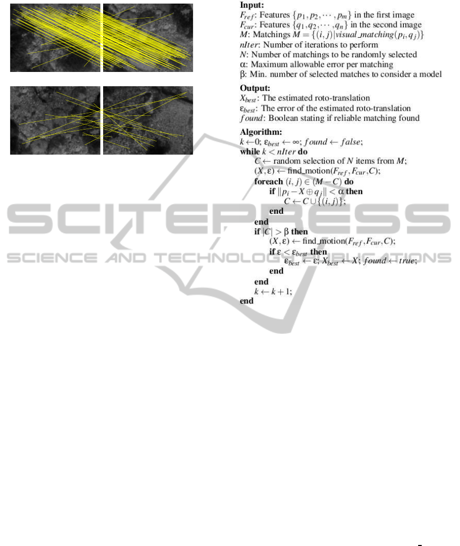
(a)
(b)
Figure 1: Feature matching using underwater images. Yel-
low lines represent correspondences between features. (a)
Overlapping images (b) Non overlapping images.
then converted to meters by assuming a locally flat
floor and providing the distance to the bottom and the
camera focals are known. The former is measured
by the altitude sensor and the latter can be obtained
from the data sheet or through a calibration process.
Thanks to this, altitude changes, which are responsi-
ble for scale changes between images, are properly
taken into account.
Next step is to compute SIFT matchings between
the two images. In spite of the robustness of SIFT, the
reduced contrast in underwater imagery due to bad il-
lumination conditions, and the fact that most of the
gathered images look similar can lead to wrong SIFT
matchings. These wrong matchings will influence the
motion estimate even if most of the matchings are cor-
rect. Figure 1-a exemplifies this very common situa-
tion. Also, SIFT, as well as many other feature match-
ers, are likely to detect matchings even between im-
ages corresponding to non overlapping areas, as illus-
trated in Figure 1-b. These problems have to be solved
because wrong image associations, especially wrong
loop closings, may lead EKF-SLAM to unrecoverable
errors.
Accordingly, a key aspect of our data associ-
ation method is to determine whether two images
overlap or not and, if they do, compute the roto-
translation that better explain the correct matchings
between them. Our proposal is based on the fol-
lowing premise: correct matchings tend to propose a
single roto-translation whilst incorrect matchings do
not and thus can be considered outliers. The goal
of Random Sample Consensus (RANSAC) (Fischler
and Bolles, 1981) is, precisely, to find a single model
where inliers fit while discarding outliers and that is
why RANSAC has been adopted in this study.
Figure 2 shows the proposed algorithm to com-
Figure 2: RANSAC underwater image registration.
pute the roto-translation between two underwater im-
ages using RANSAC. The symbol ⊕ denotes the
compounding operator, as described in (Smith et al.,
1987). Roughly speaking, this algorithm randomly
selects a subset C of the SIFT matchings M and then
computes the roto-translation X = [x, y, θ]
T
that better
explains them. Next, each of the non selected match-
ings is tested to check if it fits X with an acceptable er-
ror level. If so, it is selected too. Finally, if the number
of selected matchings |C| exceeds a certain threshold,
the roto-translation that better explains all the selected
matchings is computed. After a fixed number of itera-
tions, the best of the computed roto-translations con-
stitutes the output of the algorithm. However, if not
enough matchings have been selected in any of the it-
erations, the algorithm assumes that the two images
do not overlap.
The algorithm relies on the so called find motion
function, which takes a set of feature matchings C
and feature coordinates in the first (F
ref
) and second
images (F
cur
) as inputs. This function provides the
roto-translation X that better explains the overlap
between the images by searching the roto-translation
that minimizes the sum of squared distances between
the matchings in C. More specifically, the roto-
translation X and the associated error ε are computed
VISAPP2014-InternationalConferenceonComputerVisionTheoryandApplications
540

Figure 3: RANSAC underwater image registration.
as follows:
X = argmin
x
f(x) (1)
ε = f(X) (2)
being
f(x) =
∑
∀(i, j)∈C
||p
i
− x ⊕ q
j
||
2
(3)
where p
i
and q
j
are feature coordinates in F
ref
and
F
cur
respectively.
As an example, Figure 3 shows the feature corre-
spondences after applying our proposal to the images
previouslyshownin Figure 1-a. It can be seen how the
wrong correspondences have been rejected and only
those explaining the true motion remain. Our pro-
posal has also been applied to the images in Figure
1-b and it correctly detected that they do not overlap.
3 VISUAL SLAM
Being based on EKF-SLAM, our approach performs
three main steps: prediction, state augmentation and
update. During the prediction, the robot pose is es-
timated by means of dead reckoning. The state aug-
mentation is in charge of storing the newly acquired
information. Finally, the measurement step updates
the prediction by associating the current image to pre-
viously stored data using the described data associa-
tion algorithm. Our proposal is to perform the mea-
surement update using only one every N frames and
thus reducing the computational cost. Henceforth, the
used frame will be called a keyframe and N will be re-
ferred to as the keyframe separation.
In this study, similarly to the Trajectory-Based
schema, the state vector X
k
is defined as follows:
X
k
= [x
0
1
, x
1
2
, x
2
3
, ··· , x
k−1
k
]
T
(4)
where each x
i−1
i
(2 ≤ i ≤ k) denotes a roto-translation
from keyframe F
i−1
to keyframe F
i
and x
0
1
represents
the initial robot pose relative to a world fixed coordi-
nate frame. Let us assume, without loss of generality,
that x
0
1
= [0, 0, 0]
T
. Thus, contrarily to other EKF Vi-
sual SLAM methods where the visual features them-
selves are stored in the state vector, our proposal re-
quires much less computational resources by storing
only the motion estimates between keyframes.
The pose of the most recent keyframe with respect
to the world fixed coordinate frame can be computed
as x
0
k
= x
0
1
⊕ x
1
2
⊕ x
2
3
⊕ · ·· ⊕ x
k−1
k
. Also, the current
robot pose can be computed by composing the last
keyframe pose estimate and the dead reckoning infor-
mation.
3.1 Prediction and State Augmentation
Under the assumption of static environment, the state
vector does not change during the EKF prediction
step. However, it has to be augmented as follows
when a new keyframe is available.
X
−
k
= [X
+
k−1
, x
k−1
k
]
T
(5)
At this point, x
k−1
k
is the rough motion esti-
mate provided by the dead reckoning sensors. Also,
keyframes are stored outside the state vector.
3.2 The Update Step
Every time a new keyframe is gathered, it is compared
with all the previously gathered ones that are within
a certain distance using the data association proposed
in Section 2. The data association tells whether the
new keyframe matches each of the previously gath-
ered ones and, if so, it provides an estimate of the
roto-translation between them. This information is
used to build our measurement vector Z
k
:
Z
k
= [(z
C1
k
)
T
, (z
C2
k
)
T
, ··· , (z
Cn
k
)
T
]
T
(6)
where C1, C2, ··· , Cn denote the keyframes that actu-
ally match the current one and z
Ci
k
represents the mo-
tion estimated by our RANSAC based approach from
the keyframe C
i
to the most recent one.
In EKF-SLAM, the observation function h
i
is in
charge of telling how z
Ci
k
is expected to be according
to the state vector X
−
k
. Because of the state vector
format, this can be computed as follows:
h
i
(X
−
k
) = x
Ci
Ci+1
⊕ x
Ci+1
Ci+2
⊕ ... ⊕ x
k−1
k
(7)
Figure 4 illustrates the idea of a measurement z
Ci
k
and the associated observation function h
i
. The full
observation function is built as follows:
h(X
−
k
) = [(h
1
)
T
, (h
2
)
T
, ..., (h
n
)
T
]
T
(8)
That is, each item in the full observation function
tells how the measurement in the same position in
TowardsRobustImageRegistrationforUnderwaterVisualSLAM
541
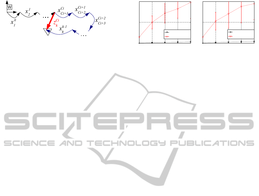
Figure 4: Illustration of a measurement (thick red arrow)
and the corresponding observation function (dashed blue ar-
rows)
Z
k
was expected according to the state vector. We
would like to emphasize that, for each couple of reg-
istered images, the whole trajectory portion that con-
nects them is explicitly corrected, contrarily to tra-
ditional methods that only explicitly correct the end-
points. For example, all the robot motions depicted as
dashed blue arrows in Figure 4 will be corrected by
the single measurement z
C
i
k
.
At this point, the standard EKF update equations,
which basically depend on the observation function
and the measurement vector, could be used. However,
in order to reduce the linearization errors our proposal
is to use an IEKF (Burguera et al., 2010). Roughly
speaking, the IEKF consists in iterating an EKF and
relinearizing the system at each iteration until conver-
gence is achieved. When this happens, the last esti-
mate constitutes the updated state vector X
+
k
.
4 EXPERIMENTAL RESULTS
4.1 Simulated Experiments
In order to show the validity of our proposal, we have
performed experiments using both a simulated and a
real underwater robot. Both the simulated and the real
robot software runs on ROS (Quigley et al., 2009),
which makes it easy to test software under simulation
before deploying it on the real robot and also to ana-
lyze the data gathered by the real robot.
For the simulated experiments the underwater
robot simulator UWSim (UWSim, 2013) was used.
The environment where the simulated robot was de-
ployed was a mosaic of a real sub-sea environment.
The pictures shown in Figure 1 are examples of the
imagery gathered by the simulated underwater cam-
era.
The simulated mission consisted in a sweeping
task, which is very common in underwater robotics.
During the mission execution, images coming from a
monocular bottom looking camera were gathered as
well as the real robot pose, which was solely used as
ground truth. Altitude was constant in this simula-
tion. Dead reckoning used in the prediction step was
1 2 3 4 5
0
0.5
1
Noise level
Error
Keyframe separation: 5 frames
SLAM−IEKF
Dead reckoning
1 2 3 4 5
0
0.5
1
Noise level
Error
Keyframe separation: 10 frames
SLAM−IEKF
Dead reckoning
(a) (b)
Figure 5: Errors in meters and 2σ bound. (a) Using
keyframe separation of 5. (b) Using keyframe separation
of 10.
computed by means of visual odometry.
Two different keyframe separations, 5 and 10,
have been tested. In our particular test case, a sep-
aration of 5 means that, in the straight parts of the tra-
jectory, the overlap between consecutive keyframes is
close to 55% of the image. A separation of 10 frames
leads to an overlap close to a 10%.
Also, in order to test the robustness of our ap-
proach in front of odometric noise, we have added
synthetic noise to odometry estimates. Five noise lev-
els have been tested for each keyframe separation.
The noise used is additive zero mean Gaussian and the
covariance ranges from a [Σ
x
, Σ
y
, Σ
θ
] = [0, 0, 0] (noise
level 1) to [Σ
x
, Σ
y
, Σ
θ
] = [4 · 10
−5
, 4 · 10
−5
, 5 · 10
−4
]
(noise level 5). The random noise was added to each
visual odometry estimate. For each configuration (5
or 10 frames of separation between keyframes) and
noise level, 100 trials have been performed in order to
obtain statistically significative results. The resulting
SLAM trajectories have been compared to the ground
truth in order to quantitatively measure their error.
The error of a SLAM trajectory is computed as the
mean distance between each of the SLAM estimates
and the corresponding ground truth pose.
The obtained results are shown in Figure 5. It can
be observed that the SLAM error is significantly be-
low the one of dead reckoning. It is clear that the
differences due to the keyframe separation and the
noise level are very small. Thus, our proposal leads
to pose estimates whose quality is almost independent
of the dead reckoning noise and the keyframe separa-
tion, as long as enough overlapping images are gath-
ered. Also, it is remarkable that the error covariances,
which are shown as 2σ bounds in Figure 5, are small
and significantly lower than those of dead reckoning.
That is, even if very different dead reckoning trajecto-
ries are used, the SLAM results are very close to the
ground truth.
Figure 6-a shows an example of the results ob-
tained with noise level 2 and a keyframe separation
of 10. The figure shows the resulting SLAM trajec-
VISAPP2014-InternationalConferenceonComputerVisionTheoryandApplications
542
−2 −1 0
−1
0
1
2
(m)
(m)
Ground truth
Visual Odometry
−2 −1 0
−1
0
1
2
(m)
(m)
Ground truth
SLAM
−2 −1 0
−1
0
1
2
(m)
(m)
Ground truth
SLAM
−2 −1 0
−1
0
1
2
(m)
(m)
Ground truth
SLAM
−2 −1 0
−1
0
1
2
(m)
(m)
Ground truth
SLAM
(a) (b) (c) (d) (e)
−2 −1 0
−1
0
1
2
(m)
(m)
Ground truth
Visual Odometry
−2 −1
−1
0
1
2
(m)
(m)
Ground truth
SLAM
−2 −1
−1
0
1
2
(m)
(m)
Ground truth
SLAM
−2 −1
−1
0
1
2
(m)
(m)
Ground truth
SLAM
−2 −1
−1
0
1
2
(m)
(m)
Ground truth
SLAM
(f) (g) (h) (i) (j)
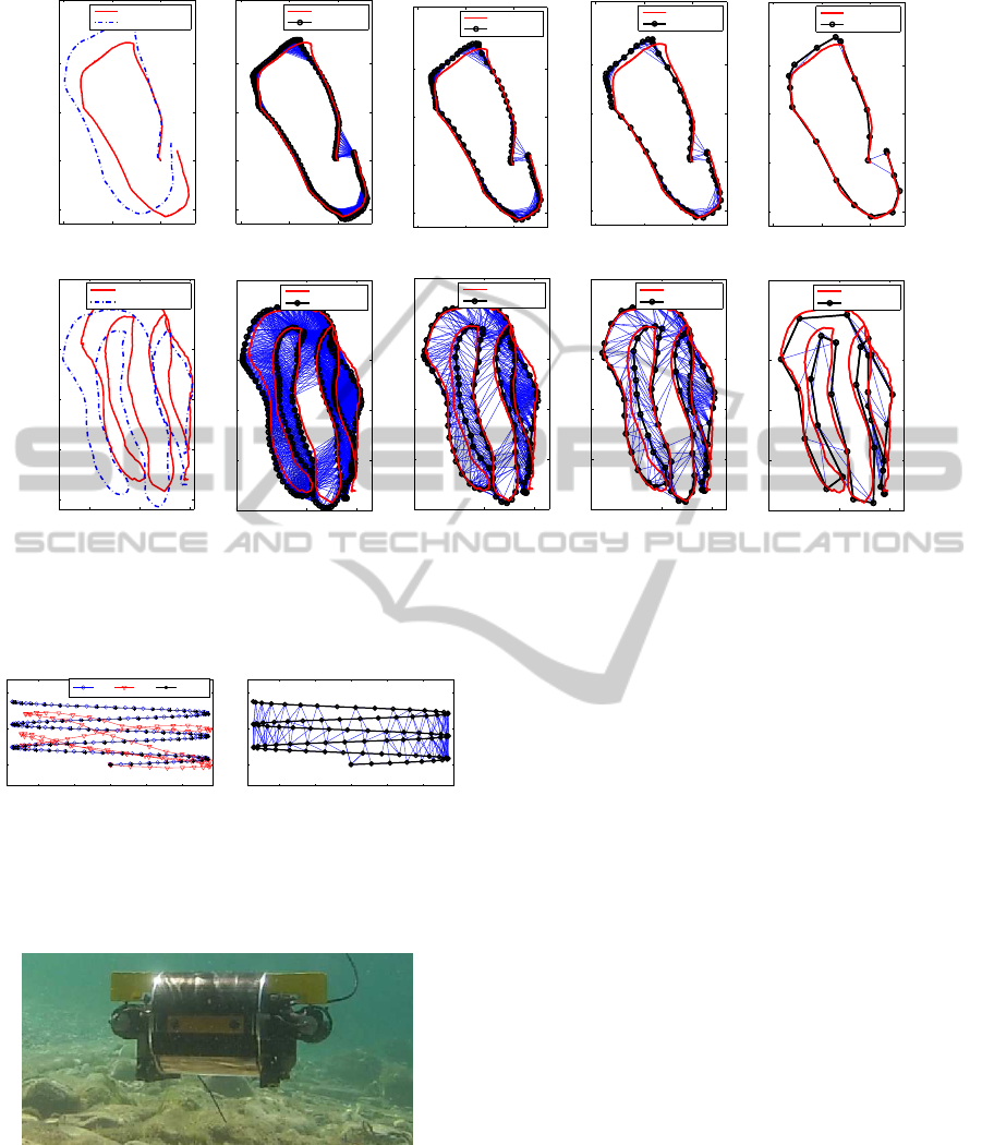
Figure 8: Experiments with the Fugu-C robot. Ground truth and visual odometry are shown for mission 1 (a) and two (f). The
resulting SLAM trajectories using keyframe separations of 10, 20, 30 and 90 in mission 1 are shown in (b), (c), (d) and (e).
The same results for mission two are depicted in (g), (h), (i) and (j).
−2 −1 0 1 2
0
1
2
m
GT DR SLAM
−2 −1 0 1 2
0
1
2
m
(a) (b)
Figure 6: Example of the results obtained with noise level
2 and keyframe separation 10. GT and DR denote Ground
Truth and Dead Reckoning. (a) Trajectories (b) Registered
images.
Figure 7: The Fugu-C.
tory, which is almost identical to the ground truth.
This is especially remarkable taking into account that
the starting dead reckoning data, as it can be seen, is
strongly disturbed by noise. Figure 6-b depicts the
data associations that have been performed during the
SLAM operation.
4.2 Fugu-C Experiments
As for the real robot experiments, they were con-
ducted using Fugu-C (Figure 7), which is a low-cost
mini Autonomous Underwater Vehicle (AUV) devel-
oped by the Systems, Robotics and Vision group in our
university. The vehicle is equipped, among others,
with a nano Inertial Measurement Unit (IMU), a pres-
sure sensor and two stereo cameras, one looking for-
ward for obstacle detection and another one looking
downwards for computing visual odometry by means
of LibViso2 (Geiger et al., 2011). The left camera
of the bottom looking stereo pair also provided the
imagery to feed our SLAM approach at a rate of 10
frames per second. Moreover, the pressure sensor was
used to correct the drift in the altitude estimates pro-
vided by the visual odometer.
The experiments were carried out in a pool 7 me-
ters long and 4 meters wide whose bottom was cov-
ered with a printed digital image of a real sea bottom.
The gathered images were registered to the whole
printed digital image to obtain a ground truth for each
experiment. Two missions were executed, consisting
of a single loop and a sweeping trajectory. The result-
ing ground truth and visual odometry for these mis-
sions are shown in Figure 8-a and 8-f. It can be ob-
served that in both cases, the odometric error is sig-
TowardsRobustImageRegistrationforUnderwaterVisualSLAM
543

nificant.
For each mission, different experiments were per-
formed using different keyframe separations. Figures
8-b to 8-e show the resulting trajectories for the first
mission using keyframe separations of 10, 20, 30 and
90, which means registering images every 1, 2, 3 and
9 seconds respectively. The results for the second
mission under the same conditions are shown in Fig-
ures 8-g to 8-j. The lines joining keyframes denote
the data associations provided by our RANSAC based
approach. Consecutive images have been always reg-
istered, although these links have not been depicted
for clarity purposes.
In all cases, the resulting trajectories are similar
to the ground truth and an important error correction
is achieved. The main effect of different keyframe
separations is the one of the temporal resolution of
the resulting SLAM trajectory but, as long as some
images could be registered and loops closed, the pose
estimates are close to the ground truth.
5 CONCLUSIONS AND FUTURE
WORK
This paper proposes a simple and practical approach
to perform underwater visual SLAM, which improves
the traditional EKF-SLAM by reducing both the com-
putational requirements and the linearization errors.
Moreover, the focus of this paper is the image reg-
istration, which is used in the SLAM data associa-
tion step making it possible to robustly close loops.
Thanks to that, as shown in the experiments, the
presented approach provides accurate pose estimates
both using a simulated robot and a real one.
Nonetheless, the presented approach makes two
assumptions that limit the environments where the
robot can be deployed. On the one hand, it is as-
sumed that the camera is always poiting downwards.
Although the experiments with the real robot show
that small changes in roll and pitch are acceptable,
avoiding this requirement is one of our future research
lines. The simplest way to solve this problem is to use
the roll and pitch provided by the gyroscopes in the
IMU and use this information to reproject the feature
coordinates. On the other hand, our proposal assumes
a locally flat floor. Some recent experiments not in-
cluded in this paper show that our proposal tolerates
real oceanic floors that are approximately flat. How-
ever, we are now working on solving this issue and
fully removing this limitation by using stereo infor-
mation.
ACKNOWLEDGEMENTS
This work is partially supported by the Spanish Min-
istry of Research and Innovation DPI2011-27977-
C03-03 (TRITON Project), Govern Balear (Ref.
71/211), PTA2011-05077 and FEDER Funds.
REFERENCES
Bar-Shalom, Y., Rong Li, X., and Kirubarajan, T. (2001).
Estimation with applications to tracking and naviga-
tion: theory algorithms and software. John Wiley and
Sons, Inc.
Burguera, A., Oliver, G., and Gonz´alez, Y. (2010). Scan-
based slam with trajectory correction in underwater
environment. In Proceedings of the IEEE/RSJ Inter-
national Conference on Intelligent Robots and Sys-
tems (IROS’10), Taipei (Taiwan).
Durrant-Whyte, H. and Bailey, T. (2006). Simultaneous
localization and mapping (SLAM): part I. IEEE
Robotics and Automation Magazine, 13(2):99–110.
Eustice, R., Pizarro, O., and Singh, H. (2008). Visu-
ally augmented navigation for autonomous underwa-
ter vehicles. IEEE Journal of Oceanic Engineering,
33(2):103–122.
Fischler, M. and Bolles, R. (1981). Random sample con-
sensus: a paradigm for model fitting with applications
to image analysis and automated cartography. Com-
munications of the ACM, 24(6):381–395.
Geiger, A., Ziegler, J., and Stiller, C. (2011). Stereoscan:
Dense 3d reconstruction in real-time. In IEEE Intelli-
gent Vehicles Symposium, Baden-Baden, Germany.
Lowe, D. (2004). Distinctive image features from scale-
invariant keypoints. International Journal of Com-
puter Vision, 60(2):91–110.
Prats, M. and Ribas, D., e. a. (2012). Reconfigurable AUV
for intervention missions: A case study on under-
water object recovery. Journal of Intelligent Service
Robotics, Sp. Issue on Marine Robotic Systems, 5:19–
31.
Quigley, M., Conley, K., Gerkey, B., Faust, J., Foote, T.,
Leibs, J., Wheeler, R., and Ng, A. (2009). ROS: an
open source robot operating system. In ICRA Work-
shop on Open Source Software.
Ribas, D., Ridao, P., Tardos, J., and Neira, J. (2007). Un-
derwater slam in a marina environment. Intelligent
Robots and Systems, 2007. IROS 2007. IEEE/RSJ In-
ternational Conference on, pages 1455–1460.
Smith, R., Cheeseman, P., and Self, M. (1987). A stochas-
tic map for uncertain spatial relationships. In Proceed-
ings of International Symposium on Robotic Research,
MIT Press, pages 467–474.
UWSim (2013). UWSim: The underwater simulator. Web.
Accessed: 20-June-2013.
VISAPP2014-InternationalConferenceonComputerVisionTheoryandApplications
544
