
Combining Test and Proof in MBAT
An Aerospace Case Study
Michael Dierkes
Rockwell Collins France, 6 avenue Didier Daurat, 31701 Blagnac, France
Keywords:
Formal Analysis, Model based Test Generation, Static Analysis, MBAT.
Abstract:
In the aerospace industry, it has become possible to use formal analysis results as certification evidence thanks
to the new version of the standard DO-178C and its formal methods supplement DO-333. Furthermore, formal
proof has a high potential of cost reduction. On the other hand, it is not possible to replace testing completely
by formal analysis, because the latter only considers more or less abstract models of the system under analysis,
and can fail due to a too high complexity. But since certain verification tasks can be carried out by formal
analysis with an advantage compared to testing, the question arises how both techniques, i.e. proof and test,
can be combined in the best way. The European project MBAT gives answers to this question, and in this
article we show how the combined approach has been applied to a relevant use case from Rockwell Collins.
1 INTRODUCTION
The aerospace industry is typically developing highly
critical embedded software, and the costs for ensuring
the safety of such systems can be very high. In the de-
velopment of the Boeing 777, software accounted for
a third of all costs, and in this third, 70% consisted
in verification and validation (V&V) costs while only
30% were devoted to software development (Feron
et al., 2012). Other aircraft manufacturers have simi-
lar figures.
The software specific certification regulatory doc-
ument, the recently updated DO-178C, characterizes
different levels of criticality from level A - the most
critical - to level E - the less critical. Depending on
the identified level, verification and validation activ-
ities are more or less intensive and therefore costly.
This certification document has recently been updated
and it also provides the formal methods supplement
RTCA DO 333. This supplement explicitly enables
the use of formal methods for critical embedded soft-
ware.
Even if formal proofs can be used as certifica-
tion evidence, they cannot completely replace testing,
since a proof is always done on a formal representa-
tion which is an abstraction from certain aspects of
the real implementation. Furthermore, it can be very
difficult to obtain a proof, such that in practice the
cost for finding a proof can be prohibitively high, and
it is in general very difficult to predict with a certain
reliability if the activity of searching for a proof will
be successful. On the other hand, highly automated
formal analysis tools are available today, and in many
cases, proofs can be found with an acceptable amount
of user effort. The particularity of formal proofs
to cover the entireness of all possible executions of
the analyzed software gives them a high potential for
cost reduction compared to testing, and therefore it is
preferable to use formal analysis as much as possi-
ble. But then, the question arises how test and proof
can be combined such that synergies between the two
techniques can be exploited in the most efficient way.
It is the aim of the MBAT project to give answers to
this question.
The ARTEMIS project MBAT is providing a new
V&V technology in form of a Reference Technology
Platform (MBAT RTP) and a methodology for its ap-
plication that enables the production of high-quality
and safe embedded systems at reduced costs. This is
made possible by an approach in which model-based
testing technologies is combined with static analysis
techniques.
In this work we present an instance of the MBAT
method applied to a redundancy management unit
which is used on aircraft. Even if this system is rel-
atively small in terms of code volume, its behavior is
complex and presents a real challenge to formal anal-
ysis tools as well as to testing approaches. However,
we show howformal analysis on model and code level
can be intertwined with testing in order to obtain a
636
Dierkes M..
Combining Test and Proof in MBAT - An Aerospace Case Study.
DOI: 10.5220/0004874906360644
In Proceedings of the 2nd International Conference on Model-Driven Engineering and Software Development (MBAT-2014), pages 636-644
ISBN: 978-989-758-007-9
Copyright
c
2014 SCITEPRESS (Science and Technology Publications, Lda.)

very high degree of confidence in the correct behav-
ior of the system.
This paper is structured as follows: In section 2,
we outline the MBAT methodology framework, and
we describe the instance of this framework that we
used for our purpose. In section 3, we present the use
case on which we applied the MBAT technology, and
in section 4, we present the analysis results that we
have obtained. We share some practical insights in
section 5, and conclude in section 6.
2 THE MBAT METHODOLOGY
The MBAT project has defined a methodological
frameworkfor the combined use of test and proof, and
a Reference Technology Platform (RTP) which gives
the technical base to apply this methodology. The ar-
chitecture of the RTP is highly modular, such that dif-
ferent tools can be combined depending on the user’s
needs.
In this section, we will give an outline of the
methodological framework of MBAT, and then we
will describe the particular instance of the MBAT
methodology that we have applied on our use case.
2.1 MBAT Main V&V Flow
The MBAT main V&V flow is shown in figure 1 taken
from (Nielsen, 2013). It consists of the following
main steps:
1. From the requirements, a (formal) specification
model is constructed that reflects the main aspects
of specified behavior.
2. From this requirement model, the design and
V&V flow can start; analysis, test, and design
models can be derived.
3. The low level design models elaborate in detail
how (as opposed to what is required) each com-
ponent is going to function.
4. The relation between the produced code for a
component and its design model is checked by dy-
namic and static analysis.
5. The integrated system is validated by means of
testing (Hardware/Processor in the Loop).
2.2 Our Instance of the MBAT
Methodology
In this section, we present the instance of the MBAT
methodology applied to our use case. It is based on
two commercial tools, and an in-house tool for model
checking developedat Rockwell Collins together with
several academic partners:
• MaTeLo: Model based test generation
tool (All4tec, 2013). MaTeLo applies usage
models based on Markov chains in order to
generate input for the system under test. This
approach is very suitable to generate realistic
input sequences, and to express the ideas of a
test engineer of how a system should be tested.
MaTeLo is developed by the MBAT partner
All4tec.
• Astr
´
ee: Code analysis tool (AbsInt, 2013). Astr´ee
is based on the technique of abstract interpreta-
tion, and is able to analyze very large programs
thanks to its high scalability. The focus of Astr´ee
are mainly non-functional properties like the ab-
sence of runtime errors due to division by zero,
arithmetic overflows, etc. However, the user can
also specify his own properties, which enables to
analyze functional properties.
An important advantage of Astr´ee is the availabil-
ity of a qualification support kit according to the
aerospace standard DO-178B, which means that
its reliability can be ensured at a level high enough
to produce certification evidence. Astr´ee is devel-
oped by the MBAT partner AbsInt.
• In-house Model Checking Tool: Developed by
Rockwell Collins for the analysis on model level.
This tool is based on modern SMT solvers, and
one of its components, called Stuff (Champion
et al., 2012), is able to find invariants of models
with linear real arithmetic in a completely auto-
mated way. Stuff is based on recent research re-
sults in the domains of SMT solving and quanti-
fier elimination.
Our in-house tool is able to analyze Simulink
models for checking if a model satisfies its spec-
ification (Miller et al., 2010). Technically, the
Simulink models are translated into Lustre, which
is then used as the base for further formal analysis
using different tools. However, it is also possible
to process Lustre models directly, if it is conve-
nient to use Lustre as modelling language.
The workflow we used is shown in figure 2, and can
be divided into the following steps:
1. From a semi-formal specification, a Simulink
model is edited, which serves as base for generat-
ing an implementation in C, either by automated
code generation, or by hand.
2. Also based on the specification, a set of formal
properties which need to be verified is derived.
CombiningTestandProofinMBAT-AnAerospaceCaseStudy
637
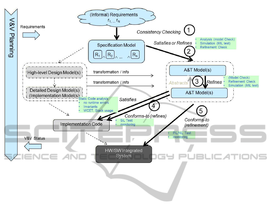
Figure 1: MBAT Main V&V Flow.
3. An analysis and test (A&T) model is edited. In
our case, we combine a MaTeLo usage model
with a Lustre model of the system which is an-
alyzed:
• The usage model is based on Markov chains,
and is used to generate the input that is injected
into the system under test.
• The Lustre model can be used to compute the
expected output, but it serves also for model
checking, and for the automated generation of
invariants.
4. An analysis of the Lustre model is performed,
with the objective to validate the model against
the specification, but also to generate information
which can be used for the code level analysis.
This can be done by using and combining differ-
ent analysis techniques depending on the nature of
the analyzed system (Champion et al., 2013). In
fact, it is often easier to find certain information
on model level than on code level, for the follow-
ing reasons:
• Knowledge from domain experts is available.
For example, if we deal with control systems,
knowledge about system invariants found by
control theory methods can be exploited. This
information is much more difficult to find on
code level.
• The information about the structure of the sys-
tem can be exploited. On code level, this struc-
ture may be partially lost.
• Powerful analysis methods are available which
can find invariants automatically on systems us-
ing real arithmetic, like for example the ana-
lyzer Stuff (Champion et al., 2012) developed
by Rockwell Collins and Onera.
The information obtained from the code level
analysis can be invariants, or invariants which
only hold if the system input is constrained in
some way. The latter can still be useful to de-
crease the number of tests.
5. The proof information obtained from the model
analysis is exploited to provethe formal properties
on code level. For example, it is checked whether
invariants which hold on the model also can be
proven on code level. Note that this is not neces-
sarily the case even if the implementation does not
contain coding errors, since on code level, round-
ing errors can occur. In some cases, it may be pos-
sible that the invariants can only be proven under
additional constraints, i.e. only for certain execu-
tions of the program, but not for all.
The result of this step is a partial formal proof,
i.e. a proof which only holds under certain con-
straints. The negation of these constraints is a
characterization of the cases which are not cov-
ered by the proof, and therefore need to be tested.
MODELSWARD2014-InternationalConferenceonModel-DrivenEngineeringandSoftwareDevelopment
638
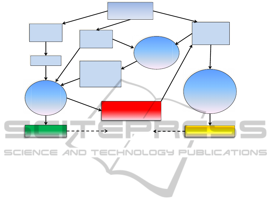
A&T Model
Usage Model
+ Lustre
Semi-formal
Specification
Simulink
Model
C code
Proof-relevant
information
(invariants,
constraints,…)
Partial Proof
Test Suite
Characterization of
uncovered cases
Code
Analysis
Astrée
Model
Analysis
MC tool
Test
Generation
MaTeLo +
MC tool
Meet Coverage
Criterion
Formal
Properties
Figure 2: Our Instance of the MBAT Methodology.
Note that the proof may be total, in which case no
testing is necessary, or it may fail completely, in
which case the property can only be tested.
6. Test are generated based on the A&T model for
the cases which are not covered by the partial
proof. We use a combination of test generation
based on usage models following the approach
of MaTeLo, and test generation based on model
checking. Using only one of these techniques sep-
arately is limited for the following reasons:
• Test generation like it is done by MaTeLo,
i.e. based on usage models in form of Markov
chains is driven by the probabilities associated
to the transitions in the model. While this ap-
proach is very useful to generate realistic test
sequences, it is not suited to generate test se-
quences which will put the system into a state
satisfying a given property.
• On the other hand, test generation based on
model checking is able to generate test se-
quences with a precise test goal, i.e. input se-
quences which lead to a desired state, but the
length of the test sequences it can generate is
very limited due to combinatorial explosion of
bounded model checking.
To overcome these limitations, we use a com-
bined approach, which exploits the intelligence
and the experience of the human user as well as
the computational power of a modern computer:
when he is shown a predicate on state variables,
we assume that a user is in general able to un-
derstand which kind of test sequences will put the
system into states which are close to states which
fulfill the given predicate. Then, bounded model
checking can be used to consider all possible in-
put sequences up to a certain depth, and to check
whether a sequence exists which puts the system
into a state fulfilling the property.
The principles which guided the design of our method
can be summarized as follows:
• Formal proof on code level should be preferred to
testing, as long as the necessary effort stays within
some acceptable limits.
• If a complete proof has not been achieved within
these limits, the insights gained by attempting the
proof should be exploited as a partial proof.
• The method must allow to use information avail-
able on higher abstraction level.
• It must be possible to exploit capabilities of mod-
ern code and model analysis tools.
• The method must allow to exploit the intuition and
the intelligence of a human user.
• The effort for maintaining the different models
must be kept as small as possible.
Our method is meant to be a powerful tool for V&V
engineers, enabling them to concentrate their experi-
ence and intuition to non-trivial test cases, and reliev-
ing them from going too much into details.
CombiningTestandProofinMBAT-AnAerospaceCaseStudy
639

3 USE CASE: TRIPLEX SENSOR
VOTER
The use case on which we will demonstrate our ap-
proach is a triplex sensor voter, i.e. a redundancy
management unit for three sensor input values. It
implements a voting algorithm which is not based
on the computation of an average value, but on the
middleValue(x, y, z) function, which returns the in-
put value which is between the minimum and the
maximum input values (for example, if y < z < x, it
would return z). Other voter algorithms which use
a (possibly weighted) average value are more sensi-
tive to one of the input values being out of the normal
bounds. Furthermore, the voter contains a fault detec-
tion mechanism, which allows to detect that one of the
input values is abnormally different from the other in-
puts, and which is then used to trigger an appropriate
fault tolerance mechanism (typically the faulty input
value will be ignored).
The specification of the triplex voter is given in
figure 3. We only give an example for an error detec-
tion mechanism here, and we do not include the ac-
tual fault tolerance mechanism. In a complete imple-
mentation, error detection mechanisms are typically
more sophisticated, and there is additional function-
ality to deactivate a faulty input. For confidentiality
reasons, we cannot give the complete design of out
triplex voter here, howeverthe simplified version cap-
tures the essential characteristics of the verification
problem. A Simulink model of the voter is shown in
figure 4.
An important requirement for the fault detection
logic is that a sensor may not be declared as faulty
as long as its value is within a certain tolerance range
around the real physical value. For a given maximal
tolerance value of a sensor, the question is how the
ErrorLimit value must be chosen in order to guaran-
tee a correct operation of the error detection. Fur-
thermore, an implementation of the voter will typi-
cally use floating point arithmetic. Then, the question
arises whether we can exclude that due to accumula-
tion of rounding errors, the fault detection can be trig-
gered erroneously. Also, it must be excluded that
runtime errors due to an arithmetical overflow can oc-
cur, either because the design is not stable, or because
rounding errors could accumulate under certain cir-
cumstances. So, we will consider the two following
requirements:
• Requirement 1: No arithmetical overflows shall
occur.
• Requirement 2: An input shall be considered
valid as long as its error stays within the tolerated
range.
Even if the voting algorithm consists only of a few
equations, its dynamic behavior is not easy to predict.
An attempt has been made by a control theory expert
to prove the stability of the voter using the methods of
control theory like Lyapunov stability analysis. How-
ever, the results were only partial and not sufficient to
be acceptable as a formal proof. Therefore, we see
a real need to apply analysis methods based on com-
puter science to this system in order to guarantee its
correct behavior.
In our analysis, we assumed that the maximal tol-
erance of the sensors is 0.5, i.e. the value reported by
a sensor can be up to 0.5 units above or below the real
physical value. We present the results of our analysis
in the next section.
4 ANALYSIS RESULTS
In this section, we present the results obtained by the
application of MBAT technologies to our use case.
4.1 Model Level Analysis
On the modellevel, we performed an analysis a Lustre
model derived from the equations which specify the
voter algorithm. Another possibility would be to gen-
erate a Lustre model automatically from the imple-
mentation model in Simulink, which might be prefer-
able if the effort of maintaining an additional analysis
model in Lustre is to be avoided.
The model level analysis is done assuming that
all computations are carried out with an infinite pre-
cision, which means that rounding errors which can
occur in a real implementation are not taken into ac-
count. A detailed presentation of the model level
analysis of the triplex sensor voter can be found
in (Dierkes, 2011).
Using our in-house tool Stuff, we can detect and
prove the following invariants in an almost com-
pletely automated way: for X,Y ∈ {A, B,C},
|EqualizationX| ≤ 1.0
|EqualizationX − EqualizationY| ≤ 1.0
|
∑
X∈{A,B,C}
EqualizationX| ≤ 1.5
Note that these invariants are highly relevant for
our requirements, since they establish an upper bound
for the equalization values as well as an upper bound
for their pairwise difference. However, at this stage
these results are only valid on model level, since they
do not take into account rounding errors which occur
when floating point arithmetic is used. The next step
consists of proving them also on code level, and if this
is not possible, to prove them at least partially.
MODELSWARD2014-InternationalConferenceonModel-DrivenEngineeringandSoftwareDevelopment
640

EqualizationA
0
= 0.0
EqualizationB
0
= 0.0
EqualizationC
0
= 0.0
EqualizedA
t
= InputA
t
− EqualizationA
t
EqualizedB
t
= InputB
t
− EqualizationB
t
EqualizedC
t
= InputC
t
− EqualizationC
t
EqualizationA
t+1
= 0.9∗ EqualizationA
t
+
0.05∗ (InputA
t
+ ((EqualizationA
t
−VoterOutput
t
) − sat
0,25
(Centering
t
)))
EqualizationB
t+1
= 0.9∗ EqualizationB
t
+
0.05∗ (InputB
t
+ ((EqualizationB
t
−VoterOutput
t
) − sat
0,25
(Centering
t
)))
EqualizationC
t+1
= 0.9∗ EqualizationC
t
+
0.05∗ (InputC
t
+ ((EqualizationC
t
−VoterOutput
t
) − sat
0,25
(Centering
t
)))
Centering
t
= middleValue(EqualizationA
t
, EqualizationB
t
,
EqualizationC
t
)
VoterOutput
t
= middleValue(EqualizedA
t
, EqualizedB
t
, EqualizedC
t
)
ValidA
t
= |EqualizationA
t
− EqualizationB
t
| < ErrorLimit or
|EqualizationA
t
− EqualizationC
t
| < ErrorLimit
ValidB
t
= |EqualizationB
t
− EqualizationA
t
| < ErrorLimit or
|EqualizationB
t
− EqualizationC
t
| < ErrorLimit
ValidC
t
= |EqualizationC
t
− EqualizationA
t
| < ErrorLimit or
|EqualizationC
t
− EqualizationB
t
| < ErrorLimit
Figure 3: Specification of the triplex sensor voter.
EqualizationA
EqualizedB
EqualizationC
EqualizationB
EqualizedA
Centering
EqualizedC
1
InputA
2
InputB
3
InputC
In1
In2
In3
Out1
Middle Value 1
In1
In2
In3
Out1
Middle Value 2
0.05
Gain
1
VoterOutput
Z
-1
Delay
Z
-1
Delay1
Z
-1
Delay2
0.05
Gain1
0.05
Gain2
0.9
Gain3
0.9
Gain4
0.9
Gain5
Saturation
In1
In2
In3
Out1
Out2
Out3
Fault Detection
2
ValidA
3
ValidB
4
ValidC
Figure 4: MATLAB Simulink model of the triplex sensor voter.
4.2 Code Level Analysis
On code level, the proof of invariants from model
level can fail for different reasons:
• The use of floating point arithmetic changes the
behavir of the implementation so much that the
invariant does not hold.
CombiningTestandProofinMBAT-AnAerospaceCaseStudy
641

• The technique in the used analysis tool does not
enable a sufficient precision.
In the first case, it is still possible that a slightly
weaker form of the invariant holds. For example,
if the possible values of a variable are proven to be
bounded by a constant C in the model, it might be
possible to prove an invariant with a constant slightly
bigger than C on the model level. This has been done
in (Dierkes and K¨astner, 2012). In the second case, it
might still be possible to prove the invariant for cer-
tain cases, which are expressed by an additional con-
straint. The cases not covered by the constraint need
to be analyzed by testing.
The code level analysis was done using Astr´ee.
Concerning the first requirement, the proof of the
upper bounds of the equalization values which were
found on model level fails with Astr´ee, howeverit was
still possible to prove the following weaker property:
As long as
|Centering| ≤ 0.25,
it holds that
|EqualizationX| ≤ 1.0001 for X ∈ {A, B,C}.
This can be considered as a partial proof of the prop-
erty that we found on model level, and it means that
tests can only provide additional information if the
centering value exceeds 0.25. The condition that the
absolute value of the centering value must be less than
0.25 has to be found by the user, but it is easy to find
since it corresponds to the saturation limit which is
applied to the centering value. In other words, the
condition simply says that the centering value must
not be saturated. We suppose that this kind of condi-
tion would naturally be examined by a test engineer.
We can even further constrain the cases which
need to be tested, because we can prove that if the
system is in a state S where |EqualizationX| ≤ 0.96,
then in every state which is reachable from S in one
transition it holds that |EqualizationX| ≤ 1.0001.
For the second requirement, we did not succeed
in proving the property with additional constraints.
However, we still can prove that if the system is in
a state S in which for X,Y ∈ {A, B,C}
|EqualizationX − EqualizationY| ≤ 0.96,
then in every state which is reachable from S in one
transition it holds that for X,Y ∈ {A, B,C}
|EqualizationX − EqualizationY| ≤ 1.0.
This result is relatively weak, since it only says that
if we want to test whether the pairwise difference of
two equalization values can exceed 1.0, we first have
to reach a state where it exceeds 0.96. However, we
can still consider this as a quality criterion for tests,
i.e. that the difference value must exceed 0.96, and
furthermore it may be possible to get a larger bound
than 0.96 by using a more precise analysis, possibly
implemented in future versions of Astr´ee. Finally, the
result was easy to obtain, and even if in the end the
verification is mainly done by testing, the additional
overhead stays low.
In (Dierkes, 2011), we havepresented an approach
in which rounding errors are over-approximated on
the model level, and the resulting verification prob-
lem is treated using an SMT solver. This approach al-
lows to obtain a significantly higher precision as tools
based on abstract interpretation, but it has two draw-
backs:
1. The complexity of the resulting SMT problem is
very high, and the scalability of this approach is
very week.
2. No qualifiable tool exists today which can trans-
late C code into an SMT formula, and check the
SMT formula for satisfiability, and probably, no
such tool will be available in the near future. Re-
sults furnished by non-qualified tools can increase
confidence that an implementation behaves cor-
rectly, but they cannot be used to replace tests with
respect to certification. Therefore, the testing ef-
fort would not be diminished.
Note that the property that the sum of all three
equalization values is bounded by 1.5 that we have
proven to be invariant on model level cannot be ex-
ploited by the current version of Astr´ee, since it can-
not be represented with sufficient precision by any ab-
stract domain implemented into this tool under its cur-
rent version.
4.3 Test Generation
For the first requirement, the test objective is to find
an input sequence which leads to a state in which one
of the equalization values, let’s say EqualizationA, is
greater than 1.0001. We know from formal analysis
that this is only possible if a state is reached which
fulfills the predicate
P = EqualizationA > 0.96 and Centering > 0.25.
Therefore, our first test objective is to find an input
sequence which leads to a state satisfying P.
For a human test engineer, an intuitive way to
reach a state which satisfies P would be first to make
EqualizationA as large as possible. This can be ob-
tained by setting InputA to 0.5 and the two other
inputs to −0.5 for a large number of cycles, which
would set EqualizationA to a value close to 1.0. Then,
in order to make the centering value maximal, InputB
MODELSWARD2014-InternationalConferenceonModel-DrivenEngineeringandSoftwareDevelopment
642
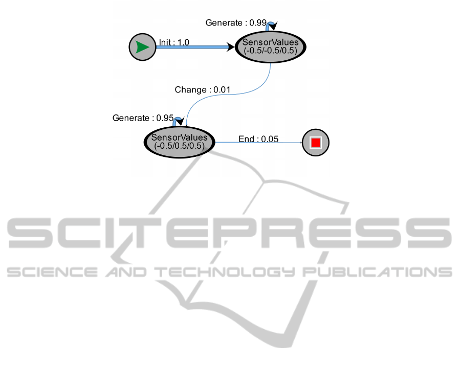
Figure 5: A MaTaLo test model.
can be set to 0.5 for a certain number of steps. It
is not easy to see how many cycles each of the two
phases should last, but a good strategy would be to
try a large number of different possibilities, by using
a probability-based test model.
A MaTeLo test model used for the generation of
test input for the voter is shown in figure 5. The num-
bers associated to the transitions of the model indi-
cate the probability that the corresponding transition
occurs. In this way, it is possible to generate a large
number of test case by a relatively simple formalism.
The test sequences derived from the test model
drive the system into a state that “almost” fulfills the
desired property in many cases. For example, a state
with EqualizationA = 0.955 and Centering = 0.257
was reached. However, among the several hundreds
of input sequences we generated using MaTeLo, none
succeeded in fulfilling P itself.
In order to increase our confidence that no state
fulfilling P can be reached, we used the final states of
the test runs as initial states for bounded model check-
ing up to a depth of 10, i.e. we considered all states
which are reachable by the model from the final states
by at most 10 transitions. But still, it was not possible
to satisfy P. We therefore concluded that with a very
high probability, states satisfying P are not reachable,
and as a consequence, that the first requirement is met
by the implementation.
Since the formal analysis results for the second
requirement where much weaker, its verification is
mainly based on testing, but still taking into account
the requirement that the test sequences must lead to
a state in which the difference between two equaliza-
tion values is greater than 0.96. Using our combined
test generation technique, we did not find any test se-
quences which falsified the property.
5 PRACTICAL ASPECTS
In a development process, it is difficult and time con-
suming to maintain several different models, espe-
cially if frequent specification changes occur. On the
other hand, a T&A model which is independent from
the design model increases the probability to discover
errors, since it represents an interpretation of the re-
quirements which is irrespective of the design.
In our approach, the T&A model consists of a test
model linked to an analysis model. Since the test
model is used for the generation of tests for cases
which are not covered by a proof, its size depends on
the width of the proof: if the latter covers many cases,
the test model can be relatively small, and therefore
easy to maintain. However, if the proof fails, the test
model must be more extensive. However, the effort of
designing a test model is justified by the time gain it
enables compared to the classical testing approach.
Concerning the analysis model contained in the
T&A model, two cases can occur:
1. If the analysis model is only used to generate
proof information, it can be derived from the
design model. This can be done automatically,
like in the Rockwell Collins tool which translates
Simulink to Lustre. The reason is that information
which is used to guide a proof on code level can
help to obtain a proof, but it cannot lead to “false”
proof. Therefore, errors in the design model can-
not lead to erroneous proofs.
2. If the analysis model is used as a test oracle, it
must be developed independently from the design
model, which clearly requires an additional effort.
However, the use of declarative languages, which
only says what needs to be computed, but not how
it is to be computed in detail, should limit this ef-
fort.
CombiningTestandProofinMBAT-AnAerospaceCaseStudy
643

6 CONCLUSIONS
We have presented the application of an approach for
combined model-based testing and formal analysis
to a non-trivial use case from the aerospace domain.
This approach has been developed within the Euro-
pean research project MBAT. Even if the code vol-
ume of the use case is relatively small, its dynamic
behavior and reachable state space have a high com-
plexity, which require a considerable validation and
verification effort if only testing is used. We have
shown how the testing effort can be reduced by us-
ing highly automated analysis tools in order to replace
certain tests, and to direct testing towards corner cases
which are difficult to deal with by the available formal
analysis tools. In our analysis, we used the commer-
cially available tools Astr´ee (formal code analysis)
and MaTeLo (model based test generation), as well
as an in-house-tool for model checking.
The principles which guided our approach are that
formal proof on code level is used as much as possi-
ble, and that it should be guided by information ob-
tained at model level. However, formal analysis is
done under the constraint that a certain amount of
effort is not exceeded, which means that a certain
amount of person hours should not be passed, and the
partial proof results obtained by then should still be
usable to decrease the amount of testing that needs
to be done. Furthermore, the testing should allow to
combine the experience and the intuition of a human
test engineer with the computational power of a ma-
chine.
In this article, we concentrated on the technical as-
pect of combining proof and testing techniques. Re-
liable figures about the cost reduction which can be
achieved are not yet available, but future investiga-
tions will include the measurement of such figures.
ACKNOWLEDGEMENTS
The research leading to these results has received
funding from the ARTEMIS Joint Undertaking un-
der grant agreement no 269335 (ARTEMIS project
MBAT) (see Article II.9. of the JU Grant Agreement)
and from the French government.
REFERENCES
AbsInt (2013). Astr´ee Run-Time Error Analyzer. http://
www.absint.com/astree.
All4tec (2013). MaTeLo Test Generation Tool. http://
www.all4tec.net/index.php/en/model-based-testing.
Champion, A., Delmas, R., and Dierkes, M. (2012). Gen-
erating property-directed potential invariants by back-
ward analysis. In
¨
Olveczky, P. C. and Artho, C., edi-
tors, FTSCS, volume 105 of EPTCS, pages 22–38.
Champion, A., Delmas, R., Dierkes, M., Garoche, P.-L.,
Jobredeaux, R., and Roux, P. (2013). Formal meth-
ods for the analysis of critical control systems mod-
els: Combining non-linear and linear analyses. In
Pecheur, C. and Dierkes, M., editors, FMICS, volume
8187 of Lecture Notes in Computer Science, pages 1–
16. Springer.
Dierkes, M. (2011). Formal analysis of a triplex sen-
sor voter in an industrial context. In Sala¨un, G.
and Sch¨atz, B., editors, Proceedings of the 16th In-
ternational Workshop on Formal Methods for Indus-
trial Critical Systems, FMICS 2011, volume 6959 of
LNCS. Springer.
Dierkes, M. and K¨astner, D. (2012). Transferring stability
proof obligations from model level to code level. In
Proceeding of ERTS 2012.
Feron, E., Brat, G., Garoche, P.-L., Manolios, P., and Pan-
tel, M. (2012). Formal methods for areospace appli-
cations. FMCAD 2012 tutorial.
Miller, S. P., Whalen, M. W., and Cofer, D. D. (2010).
Software model checking takes off. Commun. ACM,
53(2):58–64.
Nielsen, B. (2013). MBAT Overall T&A Methodology.
Project Delivrable Document D
WP2.1 2 1.
MODELSWARD2014-InternationalConferenceonModel-DrivenEngineeringandSoftwareDevelopment
644
