
Two-dimensional Numerical Simulation Method for Convective Flow
Structure Induced by Chemical Concentration Waves
Atsushi Nomura
1
, Tatsunari Sakurai
2
and Hidetoshi Miike
3
1
Faculty of Education, Yamaguchi University, Yoshida 1677-1, Yamaguchi 753-8513, Japan
2
Graduate School of Science, Chiba University, Inageku Yayoicho 1-33, Chiba 263-8522, Japan
3
Organization for Research Initiatives, Yamaguchi University, Tokiwadai 2-16-1, Ube 755-8611, Japan
Keywords:
Belousov-Zhabotinsky (BZ) reaction, elastic surface, Marangoni effect, Navier-Stokes equation.
Abstract:
This paper presents a two-dimensional numerical simulation method for modeling a convective flow struc-
ture induced by chemical concentration waves of Belousov-Zhabotinsky (BZ) reaction in a two-dimensional
rectangular domain of horizontal space and vertical depth. The method assumes a scenario in which an air-
liquid interface of the BZ chemical solution has an elastic property and the Marangoni effect drives the surface
motion of the interface. As a result of the surface motion, a convective flow is organized in the bulk of the
chemical solution. The bulk flow of the chemical solution is described with the Navier-Stokes equations, and
the chemical reaction is described with the Oregonator model. Thus, we couple the three systems of the bulk
flow, the chemical reaction and the surface motion described with an elastic equation in the numerical simula-
tion method. Results of several numerical simulations performed with the method show that a single chemical
concentration wave propagates with a broad convective flow structure and a chemical concentration wave train
propagates with a global flow structure. These flow structures are similar to those observed in real laboratory
experiments.
1 INTRODUCTION
Pattern dynamics have been observed in a solution
layer of the Belousov-Zhabotinsky (BZ) reaction sys-
tem (Zaikin and Zhabotinsky, 1970). A reaction-
diffusion model such as the Oregonator model de-
scribes the dynamics organizingthe spatial patterns of
chemical concentration distributions. The model rep-
resents an assembly of nonlinear chemical oscillators
coupled with the diffusion of molecules (Field et al.,
1972; Keener and Tyson, 1986; Jahnke et al., 1989).
Thus, the target patterns and spiral waves of chemi-
cal pattern dynamics are understood within the frame
work of chemical reaction and molecular diffusion.
Pattern dynamics of flow will arise with propagat-
ing chemical waves. For example, oscillatory flow
and flow waves appear in spiral chemical waves, and
a strong flow velocity of convection appears in a sin-
gle chemical wave with accelerating propagation. In
contrast to the reaction-diffusion system, only a few
studies for modeling and numerical simulation have
examined the problem of self-organized flow struc-
tures in the BZ solution.
There are several evidences showing that a chem-
ical wave train or a single chemical wave induces a
convective flow in a shallow layer of the chemical
solution (Miike et al., 2010). There is a correlation
between the two temporal changes of surface flow
velocity and chemical concentration in the chemical
wave train (Miike et al., 1988); a global surface flow
structure having a circular or spiral shape travels with
a chemical wave train (Matthiessen and M¨uller, 1995;
Sakurai et al., 1997; Sakurai et al., 2003). Surface
flow velocity at the center of a petri dish begins to
change just after triggering a single chemical wave at
an edge of the dish; the direction of the surface flow
velocity changes from anti-parallel to parallel to the
traveling direction of the chemical wave at the pas-
sage of the chemical wave (Miike et al., 1993).
There are two effects that induce flow in a chem-
ical solution: the gravity effect induced by a density
gradient and the Marangoni effect induced by a sur-
face tension gradient. Matthiessen et al. (1996) pro-
posed a model that takes account of both the grav-
ity and Marangoni effects due to the concentration
distributions of chemical species, and performed nu-
merical simulation of organized flow structure. By
quantitatively comparing the flow structure obtained
613
Nomura A., Sakurai T. and Miike H..
Two-dimensional Numerical Simulation Method for Convective Flow Structure Induced by Chemical Concentration Waves.
DOI: 10.5220/0005108506130618
In Proceedings of the 4th International Conference on Simulation and Modeling Methodologies, Technologies and Applications (SIMULTECH-2014),
pages 613-618
ISBN: 978-989-758-038-3
Copyright
c
2014 SCITEPRESS (Science and Technology Publications, Lda.)

through their numerical simulation with that obtained
in laboratory experiments, they concluded that the
Marangoni effect due to a chemical concentration
gradient is more dominant than the gravity effect in
a single chemical wave (Matthiessen et al., 1996).
Yoshikawa et al. (Yoshikawa et al., 1993) and In-
omoto et al. (Inomoto et al., 2000) measured the de-
pendence of surface tension on the concentrations of
chemical species in the BZ solution; these experi-
mental results support the results of Matthiessen et
al. (1996).
More recently, Rossi et al. found chemical con-
centration waves segmented in the BZ reaction sys-
tem (Rossi and Liveri, 2009), and performed its nu-
merical simulation with the gravity and Marangoni
effects (Rossi et al., 2012). They explored how the
chemical concentration distributions and flow struc-
ture change with a thickness of the chemical solution
layer and excitability of the chemical reaction. As re-
sults, they found that the segmented waves are caused
in a thick chemical solution and with high excitabil-
ity, and in that case the gravity effect is more effec-
tive than the Marangoni one in the segmented waves.
Rongy et al. focused on the front of a chemical con-
centration wave propagating in a shallow layer of a
chemical solution, and performed its numerical simu-
lation with the solutal Marangoni effect under a vari-
ety of thickness of the solution layer without the grav-
ity effect (Rongy and De Wit, 2007). They confirmed
the dependence of a traveling speed on the thickness;
the speed increases with the thickness of the solu-
tion. These results of numerical simulation were per-
formed on the situation of propagating chemical reac-
tion wave(s) in a thick solution layer more than 1 mm.
Nomura et al. (2004) assumed that the air-liquid
interface of the chemical solution has an elastic prop-
erty. Then, they proposed a one-dimensional model
that consists of the Oregonator model and an elas-
tic equation driven by the Marangoni effect. The
one-dimensional model reproduced the global surface
flow structure observed in a chemical wave train, and
the surface flow velocity induced in far from a single
chemical wave.
This paper presents a two-dimensional numeri-
cal simulation method for modeling convective flow
structures induced by chemical concentration waves
of BZ reaction in a two-dimensional rectangular do-
main of horizontal space and vertical depth. Accord-
ing to the result of Nomura et al. (2004), we assume
that the air-liquid interface of the chemical solution
is governed by the elastic equation; the bulk flow of
the solution is governed by the Navier-Stokes equa-
tions. Although deformation of the interface was ob-
served in previous laboratory experiments (Sakurai
Displacement
Chemical solution
x
Elastic surface
d(x,t)
F(x,t)
Figure 1: One-dimensional model for the air-liquid inter-
face of a chemical solution. The model assumes that the
surface has an elastic property. The surface tension gra-
dient of the Marangoni effect induces a force F(x,t) [see
Eq. (5)], which induces surface displacement d(x,t) of the
elastic surface [see Eq. (3)].
et al., 2004), we do not consider the deformation in
this paper. Thus, by coupling the three systems of
the bulk flow, the chemical reaction and the surface
motion, we carry out numerical simulation of the two
dimensional system. Simulation results show that a
broad convective flow structure is organized with a
single chemical propagation wave and a global flow
structure is organized with a chemical wave train.
2 MODELING AND NUMERICAL
SIMULATION METHOD
2.1 Modeling Study
In the BZ reaction system, concentration distributions
of chemical species u and v are governed by a set
of reaction-diffusionequationswith convection terms,
as follows:
∂u
∂t
= D
u
∇
2
u+ R
u
(u,v) − V· ∇u,
∂v
∂t
= D
v
∇
2
v+ R
v
(u,v) − V· ∇v, (1)
in which t denotes time, D
u
and D
v
are the diffusion
coefficients of ∇
2
u and ∇
2
v, and V· ∇u and V· ∇v are
convection terms. The functions R
u
(u,v) and R
v
(u,v)
are the nonlinear chemical reaction terms, which are
described by
R
u
(u,v) =
1
ε
u(1− u) − fv
u− q
u+ q
,
R
v
(u,v) = u− v, (2)
in the Oregonator model with positive constants of
f and q and a positive small constant ε (Keener and
Tyson, 1986; Jahnke et al., 1989).
According to the scenario proposed by (Nomura
et al., 2004), we also assume that the air-liquid inter-
face of the chemical solution has an elastic property,
and the Marangoni effect induces horizontal surface
displacement, as shown in Fig. 1. An elastic equation
defined in space x and time t describes surface dis-
SIMULTECH2014-4thInternationalConferenceonSimulationandModelingMethodologies,Technologiesand
Applications
614

placement d(x,t) induced by a force F(x,t), as fol-
lows:
∂
2
d
∂t
2
+ a
∂d
∂t
= D
d
∇
2
d + F(x,t), (3)
in which a and D
d
are constants. A temporal change
of surface displacement d brings about the surface
flow velocity of
V
s
=
∂d
∂t
. (4)
The function F(x,t) represents the force induced by
the surface tension gradient of the Marangoni effect.
If we assume that the distribution of the chemical
species v(x,t) primarily induces the surface tension
gradient (Matthiessen et al., 1996; Yoshikawa et al.,
1993), the force F(x,t) becomes
F(x,t) = b
∂v
∂x
, (5)
with a coefficient b. Thus, the previous model pro-
posed by Nomura et al. (Nomura et al., 2004) con-
nects the Oregonator type reaction-diffusion model
[Eqs. (1) and (2)] and the elastic equation [Eq. (3)]
through the Marangoni effect of Eq. (5) and the con-
vection terms.
The Navier-Stokes equations describe a flow field
in the bulk of the BZ chemical solution. We considera
rectangular domain consisting of the horizontal space
x and a vertical depth z. The Navier-Stokes equa-
tions defined in the two dimensional space (x, z) can
be converted into two equations governing a stream
function ϕ and a vorticity function ω, as shown in
∇
2
ϕ = −ω,
∂ω
∂t
+
∂ϕ
∂z
∂ω
∂x
−
∂ϕ
∂x
∂ω
∂z
= µ∇
2
ω, (6)
in which V = (V
x
,V
z
) = (∂ϕ/∂z, −∂ϕ/∂x) represents
two-dimensional flow velocity and µ represents the
kinematic viscosity of the chemical solution. We do
not take account of the gravity effect due to the den-
sity distribution, as suggested by (Matthiessen et al.,
1996).
In the bulk of the chemical solution, the Orego-
nator model of Eqs. (1) and (2) defined in the two-
dimensional space (x,z) describes the chemical con-
centration distributions of u(x,z,t) and v(x,z,t).
The model proposed here couples the Navier-
Stokes equations of Eq. (6) with the Oregona-
tor model of Eqs. (1) and (2), through the one-
dimensional elastic equation of Eq. (3). The elastic
equation describes the displacement of the air-liquid
interface of the chemical solution. Surface flow ve-
locity or surface displacement induces a convective
flow in the bulk of the chemical solution. Thus, we
make use of the surface flow velocity V
s
obtained by
the elastic equation as the boundary condition of V
x
in
the Navier-Stokes equations.
Elastic surface
+ Navier-Stokes equations
Oregonator model
x
z
L
x
L
z
A B
CD
Figure 2: Rectangular domain utilized for modeling the
two-dimensional flow field of a chemical solution. The
Navier-Stokes equations describe a flow field in the bulk of
the chemical solution [see Eq. (6)]; the Oregonator model
with convection terms describes the chemical reaction in the
domain [see Eq. (1)]. The elastic equation given in Eq. (3)
governs the displacement of the air-liquid interface (A–B)
of the domain. The right wall (B–C), the bottom (C–D), and
the left wall (D–A) are rigid. See Eq. (7) for the boundary
conditions. The rectangular domain consists of a horizontal
axis x (space) and a vertical axis z (depth); L
x
represents the
width of the rectangular domain and L
z
represents its depth.
2.2 NUMERICAL SIMULATION
METHOD
We discretize the model equations of Eqs. (1), (3) and
(6) with a finite difference method, in which spatial
differences discretizing horizontal space and vertical
depth are denoted by δx and δz and a temporal differ-
ence is denoted by δt.
On the one-dimensional elastic equation govern-
ing the air-liquid interface, we discretized the Lapla-
cian operator ∇
2
in Eq. (3) with the three-point
centered difference formula and the Crank-Nicolson
scheme. Then, we solve a set of linear equations by
the LDU decomposition method.
In the bulk of the chemical solution, we explicitly
discretized the Laplacian operator ∇
2
in Eqs. (1) and
(6) with the five-point centered difference formula.
We discretized the convection terms of Eq. (1) with
the two-point upwind scheme. We solved the set of
linear equations obtained from ∇
2
ϕ = −ω by the suc-
cessive overrelaxation (SOR) method.
The initial conditions are u = v = d = ϕ = ω = 0
over the one- or two-dimensional space. A single
chemical wave can be generated by setting the distri-
bution u(x, z,t = 0) as u = 1.0 in a local area. A wave
train, namely, a series of chemical waves is generated
at a time interval λ.
The Direchlet boundary condition governs both
ends of the surface displacement (d = 0). The Neu-
mann boundary condition governs the four sides of
the two-dimensional rectangular domain of the two
distributions u and v (∂u/∂x = ∂u/∂z = ∂v/∂x =
∂v/∂z = 0).
On the Navier-Stokes equations, the stream func-
tion ϕ is zero along the four sides, and the vorticity
function ω along the four sides: A–B, B–C, C–D and
Two-dimensionalNumericalSimulationMethodforConvectiveFlowStructureInducedbyChemicalConcentrationWaves
615

D–A are governed by
A–B: ω(iδx,0) = −2[V
s
δz− ϕ(iδx, δz)]/δz
2
,
B–C: ω((I − 1)δx, jδz) = −2ϕ((I − 2)δx, jδz)/δx
2
,
C–D: ω(iδx,(J − 1)δz) = −2ϕ(iδx,(J − 2)δz)/δz
2
,
D–A: ω(0, jδz) = −2ϕ(0, jδz)/δx
2
, (7)
in which V
s
represents the surface flow velocity of
Eq. (4); the grid point (iδx, jδz) represents the dis-
crete position of (x,z). Let L
x
× L
z
be the size of the
two-dimensional space considered here as shown in
Fig. 2. Then, in the boundary conditions of Eq. (7)
I = [L
x
/δx] and J = [L
z
/δz] represent the total num-
bers of grid points in space x and depth z.
In the following numerical simulations, finite dif-
ferences in space, depth and time were fixed at δx =
δz = 1/5 and δt = 1/10000. The parameter settings
were fixed at D
u
= 1.0,D
v
= 0.6, q = 2.0× 10
−3
,ε =
0.01, and µ = 6.7 (Jahnke et al., 1989).
3 NUMERICAL SIMULATION
RESULTS
A previous model (Matthiessen et al., 1996; Diewald
et al., 1996) connects the Oregonator model of
Eqs. (1) and (2) with the Navier-Stokes equations
given in Eq. (6) through the Marangoni effect due
to a chemical concentration gradient of v along the
air-liquid interface. The model takes account of the
Marangoni effect as the boundary condition of the
surface flow velocity V
x
along the air-liquid interface,
as follows:
∂V
x
∂z
= M
a
∂v
∂x
, (8)
in which M
a
is a constant. The boundary condi-
tions on ω for the side walls and bottom of the two-
dimensional domain, and those on u, v and ϕ for the
four sides of the domain are the same as those of the
proposed model. The initial conditions of u, v, ϕ and
ω are the same as those of the proposed model. The
previous model does not takes account of the grav-
ity effect. The discretization methods utilized in the
previous model are the same as those in the proposed
model.
In order to compare the proposed model with the
previous model mentioned above, we carried out two-
dimensional numerical experiments on a single chem-
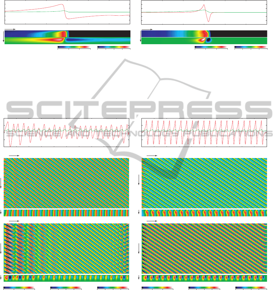
ical wave. Figure 3(a) shows the result of the pro-
posed model; the single chemical wave triggered at
the left end travels in the horizontal position approx-
imately x = 220 towards the right end. The surface
flow velocity anti-parallel to the traveling direction
of the chemical wave induces a flow structure with
a counter-clockwise direction in the bulk; this flow
structure has some spatial extent in front of the chem-
ical wave. Figure 3(b) shows the result of the previ-
ous model (Matthiessen et al., 1996; Diewald et al.,
1996). While the single chemical wave is traveling in
a similar horizontal position (x = 220), a flow struc-
ture exists in the vicinity of the chemical wave. There
is no spatial extent of the flow structure in front of the
chemical wave.
Results of previous laboratory experiments show
that some spatial extent of a flow structure exists in
front of the single chemical wave. Therefore, we sug-
gest that the proposed model is able to reproduce a
more plausible flow structure than the previous model
for a single chemical wave.
We carried out additional numerical experiments
on a wave train in a two-dimensional domain, in
which chemical waves triggered at the left end trav-
eled in the two-dimensional domain towards the right
end. Figure 4(a) shows the result of the proposed
model. A particular chemical wave organizesa pair of
small convection rolls having clockwise and counter-
clockwise directions.
Around the middle of the horizontal position in
the two-dimensional domain, particular pairs of the
convection rolls are almost symmetrical and most of
them have similar strength of convection. Compared
with these pairs traveling in the middle, those on the
left side of the domain lack symmetry and have dif-
ferent strengths. The asymmetrical convection rolls
with different strengths induces a global flow struc-
ture. In comparison with the results of the proposed
model, the result of the previous model do not show
such the global flow structure, as shown in Fig. 4(b).
Uniform pairs of convection rolls travel maintaining
almost uniform strength and symmetry.
In these two-dimensional numerical experiments,
the absolute flow velocity obtained by the proposed
model was small compared with that obtained using
the previous model. Two-dimensional numerical ex-
periments with the proposed model broke down for
large values of b and D
d
, and we therefore had to
choose sufficiently small values of b and D
d
to ob-
tain results. In spite of such small values, the pro-
posed model successfully presented the global flow
structure. The model is a plausible candidate for
simulating the two-dimensional flow structures self-
organized in the systems of a single chemical wave
and of a chemical wave train.
SIMULTECH2014-4thInternationalConferenceonSimulationandModelingMethodologies,Technologiesand
Applications
616
-10
0
10
160 180 200 220 240 260 280
-0.4
0
0.4
V
x
v
V
x v
x
x
z
0 0.15
v
0.05 0.10
-6.0 6.0
ϕ
0-3.0 3.0
(b-1)
(b-3)
(b-2)
-0.04
0
0.04
160 180 200 220 240 260 280
-0.4
0
0.4
V
x
v
V
x
v
x
x
z
0 0.15
v
0.05 0.10
-0.04 0.04
ϕ
0-0.02 0.02
(a-1)
(a-3)
(a-2)
(a) (b)
Figure 3: Result of a two-dimensional numerical experiment on a single chemical wave with (a) the proposed model and
(b) the previous model (Matthiessen et al., 1996; Diewald et al., 1996). Figures (a-1) and (b-1) show one-dimensional spatial
distributions of the concentration v and the flow velocity V
x
along the air-liquid interface of the two-dimensional domain in
the range of 160 ≤ x < 280. Figures (a-2) and (b-2) show two-dimensional spatial distributions of v, and Figs. (a-3) and
(b-3) show distributions of the stream function ϕ, in the ranges of 160 ≤ x < 280 and 0 ≤ z < 5. The spatial size of the
two-dimensional domain was (L
x
× L
z
) = (400× 5). All the distributions were obtained at t = 10. The single chemical wave
was triggered at the left-top position at t = 0. The parameter settings of Eqs. (2), (3), (6) and (1) were D
d
= 10
3
, a = 0.5,
b = 100 and f = 2.5; see Section 2.2 for the other parameter settings.
-6.0
-3.0
0
3.0
6.0
0 40 80 120 160 200
-1.0
-0.5
0
0.5
1.0
V
x
v
x
V
x
(10
-4
)
v
x
t
t
180
200
180
200
0 200
x0 200
0 0.3
v
0.1 0.2
-6.0 6.0
V
x
(10
-4
)
0-3.0 3.0
ϕ (10
-4
)
-4.0 4.00-2.0 2.0
(a)
(a-1)
(a-2)
(a-3)
x
t
t
180
200
180
200
0 200
x0 200
x
V
x
v
-10
-5
0
5
10
0 40 80 120 160 200
-1.0
-0.5
0.0
0.5
1.0
V
x
v
0 0.3
v
0.1 0.2
-10 10
V
x
0-5.0 5.0
ϕ
-6.0 6.00-3.0 3.0
z
(b)
(b-1)
(b-2)
(b-3)
z
z
z
Figure 4: Result of a two-dimensional numerical experiment on a chemical wave train with (a) the proposed model and
(b) the previous model (Matthiessen et al., 1996; Diewald et al., 1996). Figures (a-1) and (b-1) show one-dimensional spatial
distributions of the concentration v and the flow velocity V
x
along the air-liquid interface of the two-dimensional domain at
t = 200. Figures (a-2) and (b-2) show spatiotemporal plots of v with their two-dimensional spatial distributions at t = 200.
Figures (a-3) and (b-3) show spatiotemporal plots of V
x
with their two-dimensional spatial distributions of the stream function
ϕ at t = 200. Chemical waves were triggered at the time intervals of λ = 1.55 at the left-top position of the two-dimensional
domain. The spatial size of the two-dimensional domain was (L
x
× L
z
) = (200× 5). The parameter settings of Eqs. (2), (3)
and (5) were f = 1.0, D
d
= 100, a = 1.0 and b = 0.1; see Section 2.2 for the other parameter settings.
Two-dimensionalNumericalSimulationMethodforConvectiveFlowStructureInducedbyChemicalConcentrationWaves
617

4 CONCLUSIONS
This paper presented a numerical simulation method
for explaining convective flow structures induced by
a single chemical wave and a chemical wave train in a
chemical solution layer of the BZ reaction. According
to the previous result by Nomura et al. (Nomura et al.,
2004), the model assumes a scenario in which the
surface of the chemical solution has an elastic prop-
erty. The concentration gradient of a chemical species
along the surface induces a surface tension gradient,
and brings about displacement of the elastic surface
through the Marangoni effect. In addition, the surface
displacement causes a bulk flow of the chemical solu-
tion, which can be described with the Navier-Stokes
equations. Thus, the numerical simulation method
proposed here couples an Oregonator type reaction-
diffusion model with the Navier-Stokes equations via
the elastic equation.
We carried out numerical experiments with the
proposed model on a single chemical wave and a
chemical wave train. The results of these experiments
show that the proposed model reproduces the flow
structures observed in laboratory experiments. That
is, a flow structure induced by a single chemical wave
has some spatial extent in front of the chemical wave;
a flow structure induced by a chemical wave train has
a global flow structure due to asymmetric convection
rolls. A previous model did not predict such the flow
structures in our numerical experiments. These re-
sults suggest that the assumption of the elastic prop-
erty helps us to understand flow structures observed
in the solution layer of the BZ reaction.
REFERENCES
Diewald, M., Matthiessen, K., M¨uller, S. C., and Brand,
H. R. (1996). Oscillatory hydrodynamic flow due to
concentration dependence of surface tension. Physical
Review Letters, 77:4466–4469.
Field, R. J., Koros, E., and Noyes, R. M. (1972). Os-
cillations in chemical systems. II. Thorough analysis
of temporal oscillation in the bromate-cerium-malonic
acid system. Journal of American Chemical Society,
94:8649–8664.
Inomoto, O., Abe, K., Amemiya, T., Yamaguchi, T., and
Kai, S. (2000). Bromomalonic-acid-induced transi-
tion from trigger wave to big wave in the Belousov-
Zhabotinsky reaction. Physical Review E, 61:5326–
5329.
Jahnke, W., Skaggs, W. E., and Winfree, A. T.
(1989). Chemical vortex dynamics in the Belousov-
Zhabotinskii reaction and in the two-variable orego-
nator model. Journal of Physical Chemistry, 93:740–
749.
Keener, J. P. and Tyson, J. J. (1986). Spiral waves in the
Belousov-Zhabotinskii reaction. Physica D, 21:307–
324.
Matthiessen, K. and M¨uller, S. C. (1995). Global flow
waves in chemically induced convection. Physical Re-
view E, 52:492–495.
Matthiessen, K., Wilke, H., and M¨uller, S. C. (1996). In-
fluence of surface tension changes on hydrodynamic
flow induced by traveling chemical waves. Physical
Review E, 53:6056–6060.
Miike, H., Miura, K., Nomura, A., and Sakurai, T. (2010).
Flow waves of hierarchical pattern formation induced
by chemical waves: The birth, growth and death of
hydrodynamic structures. Physica D, 239:808–818.
Miike, H., M¨uller, S. C., and Hess, B. (1988). Oscilla-
tory deformation of chemical waves induced by sur-
face flow. Physical Review Letters, 61:2109–2112.
Miike, H., Yamamoto, H., Kai, S., and M¨uller, S. C. (1993).
Accelerating chemical waves accompanied by travel-
ing hydrodynamic motion and surface deformation.
Physical Review E, 48:R1627–R1630.
Nomura, A., Sakurai, T., Miike, H., and Hano, M. (2004).
Model for the Belousov-Zhabotinsky reaction and sur-
face flow structure induced by chemical concentra-
tion gradients. In Proceedings of 2004 International
Symposium on Nonlinear Theory and its Applications,
pages 363–366, Fukuoka, Japan.
Rongy, L. and De Wit, A. (2007). Marangoni flow around
chemical fronts traveling in thin solution layers: in-
fluence of the liquid depth. Journal of Engineering
Mathematics, 59(2):221–227.
Rossi, F., Budroni, M. A., Marchettini, N., and Carballido-
Landeira, J. (2012). Segmented waves in a reaction-
diffusion-convection system. Chaos, 22(3):037109
(11 pages).
Rossi, F. and Liveri, M. L. T. (2009). Chemical self-
organization in self-assembling biomimetic systems.
Ecological Modelling, 220:1857–1864.
Sakurai, T., Inomoto, O., Miike, H., and Kai, S. (2004).
Structure of surface deformation waves induced in
spiral pattern in the Belousov-Zhabotinsky reaction.
Journal of the Physical Society of Japan, 73:485–490.
Sakurai, T., Miike, H., Okada, K., and M¨uller, S. C. (2003).
Spiral flow wave in a reaction-diffusion-convection
system. Journal of the Physical Society of Japan,
72:2177–2180.
Sakurai, T., Miike, H., Yokoyama, E., and M¨uller, S. C.
(1997). Initiation front and annihilation center of
convection waves developing in spiral structures of
Belousov-Zhabotinsky reaction. Journal of the Physi-
cal Society of Japan, 66:518–521.
Yoshikawa, K., Kusumi, T., Ukitsu, M., and Nakata, S.
(1993). Generation of periodic force with oscillat-
ing chemical reaction. Chemical Physics Letters,
211:211–213.
Zaikin, A. N. and Zhabotinsky, A. M. (1970). Concen-
tration wave propagation in two-dimensional liquid-
phase self-oscillating system. Nature, 225:535–537.
SIMULTECH2014-4thInternationalConferenceonSimulationandModelingMethodologies,Technologiesand
Applications
618
