
Robot Workspace Monitoring with Redundant Structured Light
Cameras
A Preliminary Investigation
Hans Dermot Doran and Simon Marti
Institute of Embedded Systems, Zurich University of Applied Science, Technikumstrasse 9, 8401 Winterthur, Switzerland
Keywords: Robotics, Monitoring, Image Processing, Structured Light Scanning Cameras, 3D Cameras.
Abstract: In this paper we propose the use of a redundant array of structured light scanning cameras to monitor a
collaborative robot workspace. We present the model and suggest a minimum number of such cameras
required to monitor a particular area. We then propose a concept for segmenting the workspace into
different sub volumes to allow for different categories of obstacles. We then propose that a voting scheme
will allow us to process multiple camera inputs in real-time in a safe fashion. We perform initial
experiments and draw appropriate conclusions before defining further work.
1 INTRODUCTION
Vision-monitoring of robot workplaces has been a
research theme for some ten years. The general issue
is how to cope with depth information which is why,
absent appropriate technology, early research
focused on stereo vision and other algorithmic
methods. Advances in sensor technology have
allowed researchers to investigate applicability of
the new generations of Structured Light Scanning
(SLSC), 3D (3DC) and Time of Flight (ToF)
cameras now available. Most research still appears
to focus on the vision processing elements of the
detection and monitoring tasks. The cheapness of
these cameras makes redundant arrays of such
cameras industrially feasible and we propose
suitable techniques exploiting such arrays. The
advantages that redundant arrays give us are the
ability to monitor infinitely large areas, handling
image overlap at low computational expense, whilst
continuously maintaining line-of-sight, always a
challenge in a factory environment.
The paper is structured accordingly – after
considering previous work we present the use-case
and deliberations on the geometry of the camera
system. We then examine the obstacle model and
propose a voting scheme to enable safe and real-time
processing of redundant camera pictures possible.
We then present some initial practical work and
finish off with appropriate conclusions and further
work.
1.1 Previous Work
On the factory floor robots are employed under
recognised regulatory guidelines. Vasic (Vasic)
provides a good introduction to the considerations
behind robot-human interaction whilst Gall (Gall)
presents the general point of view of safety
certification authorities. In essence robot-human
interaction is determined, depending on country, by
the interrelated ISO10218 (Europe), (ISO 2011) and
the ANSI/RIA R15.06-2012 (USA, Japan) (ANSI
1999). Industrial robots are generally confined to
cages and the robot comes to a halt once a cage door
is opened. This makes sense from a safety point of
view but does hinder job turnaround and throughput.
Counter-solutions on offer based on monitoring of
surrounding areas include ABB and Pilz (ABB,
Pilz), the disadvantage with these solutions is that
the robot still comes to a halt once the operator is in
the robot workspace. The second strategy is to use
force-control on the robot to ensure that any
damaging effects of collisions are minimised. Such
systems have been proposed in research (Infante)
and implemented in industrial situations
(Schmidhauser). Our work belongs in the category
of implementation of safety policies based on some
form of intrusion detection. This has long been a
subject of interest and currently is being researched
in various robot-application domains including
artificial intelligence robots, service robotics,
automotive and autonomous vehicles as well as
611
Dermot Doran H. and Marti S..
Robot Workspace Monitoring with Redundant Structured Light Cameras - A Preliminary Investigation.
DOI: 10.5220/0005120306110617
In Proceedings of the 11th International Conference on Informatics in Control, Automation and Robotics (ICINCO-2014), pages 611-617
ISBN: 978-989-758-040-6
Copyright
c
2014 SCITEPRESS (Science and Technology Publications, Lda.)

industrial robotics. Academic work has been done
on the strategies in human-industrial robot
interaction (
Kulić
, Najmaei, Lacevic), on object
tracking (Elshafie, Lenz 2009), motion planning
(Hong, Graf) and interaction (Zanchettin, Heyer). In
particular intrusion detection using a camera has
provided a fertile field with newer publications
(Lenz 2014) using a time-of-flight camera as
opposed to the RGB, array of RGB or stereo RGB
configurations proposed by the other authors. We
see limited treatment of real-time issues in research
papers.
2 PRACTICAL
CONSIDERATIONS
2.1 Use Case
In this use case we assume the simple case of a
rectangular work area with three robots of the 5-15
kg class (lifting weight) arranged in a triangular
formation (Figure 1). The reason for this
classification is that industrial robots available in
this performance class are still of the classically stiff
construction meaning that they themselves weigh
multiples of this mass and hence are a danger to
human operators should a collision occur. We
assume that raw material comes in on the right hand
side and the robots are used to move material from
entry to a machine (M1), for instance a drilling
machine. The robot may hold the piece whilst it is
being worked or it might lock it into an automated
vice. The robot may move the piece after it has been
worked to a second machine or the second robot
may collect it from the machine (f.i. M1) and move
it to the second (for instance M2). This configuration
is assumed to be inherently flexible, that is small job
lots of size equal or greater to one. The work area is
approachable from all sides.
2.2 Monitoring
The useful depth of field of a Kinect, a cheaply
available structured light scanning camera (SLSC)
extends from 0.8-4 meters. If we superimpose the
depth of field of the Kinect on the work area of the
robot installation we can see that three Kinects are
required to cover the work area (without securing
the approaches to the work area). The sensors are
line of sight and therefore cannot provide complete
monitoring in the case of spurious occlusions and
occlusions caused by the robots themselves. For a
functionally safe system sensor redundancy is
required. We show a system with nine Kinects
which provides redundancy on all coordinates
regardless of the position of the robots. Our
approach is to monitor obstacles without reference to
history, that is the obstacle map is re-calculated
every sampling period and the decision on the future
behaviour of the robot is made based on information
available in this sampling instance.
Figure 1: Example Use Case of Robot Workspace
Monitoring. The black rectangles represent Kinects and
the red lines their useful field of vision.
2.3 Safety Policies
When an obstacle is detected the robots have to react
in some way. We call this reaction the
implementation of a safety policy. We implement
the three safety policies as proposed by Casa (Casa).
These are Emergency Stop, Slow Down and Re-
Route. The process as to which policy should be
implemented is dependent on some decision process
which shall not be further discussed.
2.4 Obstacle Model
We are aware that the use of the word obstacle in the
context of human- robot interaction is misleading in
a safety context as it places the activity of the robot
above that of a human co-worker. We shall however
stick with this convention in this paper. A robot
moves in a geometric space defined by the set of
possible coordinates denoted by C
free
. Should the
robot be required not to collide with an obstacle in
its path, the set of coordinates occupied by the
obstacle must be subtracted from C
free
. It is possible,
with the correct sensor technology, to measure with
some precision the manifold of an obstacle. In a
safety environment the numerical precision of an
obstacle must be conservative (f.i. computational
integer). In terms of optimised robot operation the
set of C
free
may be (computational) floating point.
ICINCO2014-11thInternationalConferenceonInformaticsinControl,AutomationandRobotics
612

Optimised operation means passing workbenches
and other machines as fast and as close as possible
without actually colliding. We define three types of
obstacle. A permanent, a coarse and a fine grained
obstacle.
As in general robotics systems our conception
requires a calibration phase. This phase calculates
the list of C
free
taking the coordinates of permanent
obstacles, such as the machines and the
workbenches, out of this set. These obstacles are
defined with the numerical granularity of the
kinematic model implementation of the robot. This
phase is computationally expensive and can take
several hours in a Matlab environment.
A coarse-grained obstacle is, for instance, a
human that intrudes in the workspace of a robot and
must be given a wide berth. We model a coarse-
grained obstacle as a cube with dimensions in the
order of centimetres. (Figure 2) shows that
transposition of an array of coarse-grained obstacles
over the workplace of a robot, this transposition is
known to the robot as virtual obstacles. By
activating a virtual obstacle an entire range of
coordinates can be removed from C
free
thus reducing
the number of C
free
that must be considered for
alternative path computation. A safety policy may
decide to activate virtual obstacles adjacent to one
where an obstacle was actually detected. Therefore a
suitable level of obstacle abstraction can be achieved
at low computational cost.
What is however problematic in a practical
environment is the set of obstacles between an
animate coarse-grained obstacle and a permanent
obstacle. Consider the case where a human operator
is carrying out maintenance on a running system and
shifts the raw-material tray or leaves his toolbox on
one of the work benches. This obstacle is permanent
for a period of time but due to the high (re-)
calibration cost it currently considered unfeasible to
add such obstacles to the set of permanent obstacles.
There is however no reason why the robot arm may
not pass this obstacle with the maximum speed of
the system at a distance normally associated with
permanent obstacles. We therefore, as a first
approximation, define a fine-grained obstacle as an
integer sub-volume of a coarse-grained obstacle.
This obstacle model is uniquely appropriate to
simple multi-sensor fusion. The coordinates of a
single point obstacle may be detected by any number
or type of sensors and the coarse-grained obstacle
within whose boundaries it has been detected
“turned off” thus removing that set of robot
coordinates from C
free
in one operation.
Figure 2: Robot Arm Workspace Divided into Coarse-
Grained (Virtual) Obstacles.
The sequence of events is to locate an intrusion
in the robots workspace, for which we intend to use
the Kinect, remove the set of coordinates bounded
by the coarse grained obstacle from C
free
, decide on
the appropriate safety policy and, in cases where re-
routing is feasible, find a new path for the robot.
Since we are assuming on the theoretical case where
an obstacle may appear suddenly in the workspace
of a robot, as opposed to the more realistic case of
viewing the obstacle as a vector with first and
second derivatives, we need to focus on optimising
the real-time characteristics of the detection and re-
routing algorithm.
2.5 Detection and Re-routing
Mariotti (Mariotti) investigated the real-time
characteristics of detection and re-routing using the
standard driver and detection software as supplied
with the Kinect. With a single Kinect attached to a
PC with Intel Core i7-3770 quad core processor and
3.4 GHz clock speed running Ubuntu 12.04 LTS a
total Worst Case Execution Time (WCET) of 142
ms was achieved. Whilst this WCET is useful we
consider the platform to be too expensive and, if
redundant camera arrays are used, either the WCET
is extended by the driver and obstacle detection task
of each camera or each must be performed in
parallel. Neither option is feasible from a cost point
of view. The second issue is that the standard Kinect
software detects humans and not inanimate objects.
In addition a quick experiment revealed that whilst
the Kinect software will detect a spanner held in the
same plane of a holding hand it won’t detect it
properly if the spanner is held perpendicular to the
plane of the hand (Figure 3). Therefore new software
is needed include the detection of inanimate moving
objects. The software written will be described in the
next section.
RobotWorkspaceMonitoringwithRedundantStructuredLightCameras-APreliminaryInvestigation
613
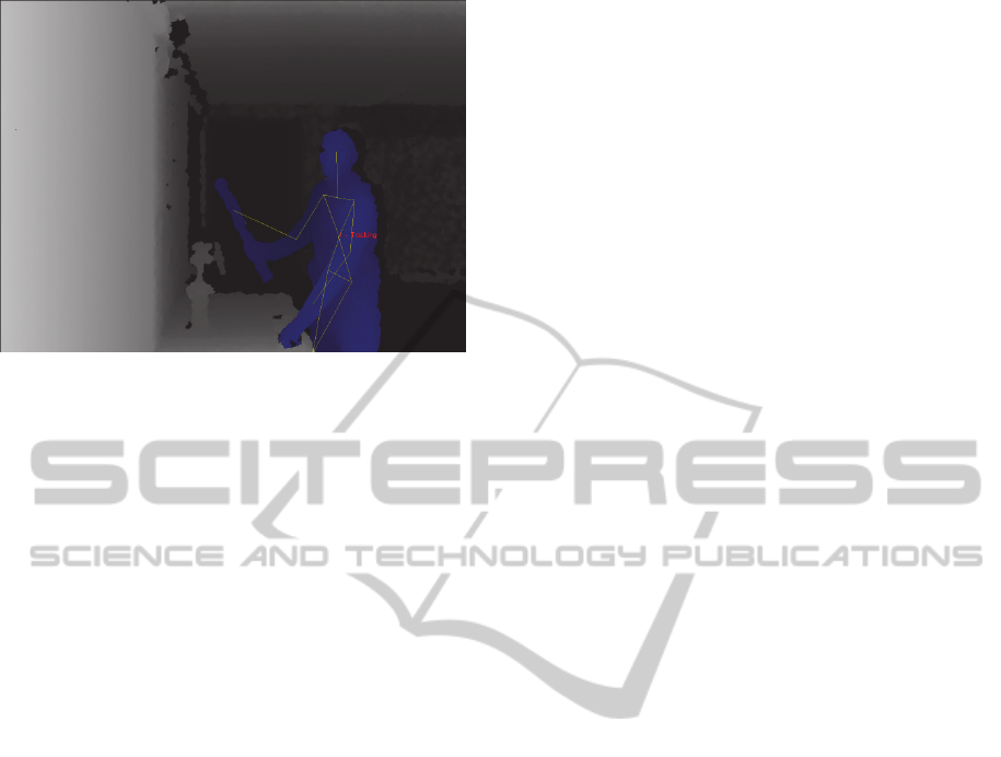
Figure 3: A Kinect Detection of a Man Holding a Spirit
Level.
2.6 Voting
In dependable applications, voting is a technique
used to determine a value derived from multiple
sensors measuring the same raw value and, often, to
determine the reliability of the sensors. Common
voting configurations are 2-out-of-3 (2oo3) or 2oo2
(f.i. Lyons). Voting is supremely suited to
monitoring as, unlike constructing a 3D image from
multiple sensors, the decision that a coarse-grained
obstacle has been activated is binary and no further
signal conditioning is required thus minimising
computational expense. The cost of a false positive,
that is loss of potential robot productivity, depends
solely on the granularity of the coarse grained
object. In this paper we propose the use of a 2oo3
voting scheme which is easily extendable to a 3oo5
scheme should further redundancy be necessary
3 BODY OF WORK
3.1 Software
The necessary computer vision algorithms were
implemented in C++ using the widely known
OpenCV (OpenCV) open source library. The
obstacle detection is done completely on the depth
map. Using this approach, traditional vision-
processing algorithms can be used and the
computational effort can be kept reasonable. In the
first step the foreground containing possible
obstacles and the static background are separated
through an averaging background subtraction
algorithm. In this case this rather simple algorithm
delivers good results, because the background model
doesn't have to be adapted to changes in ambient
lighting. The Kinect depth data suffers especially
from two kinds of noise. The first kind is noise
around the edges of objects caused by scattering of
the projected infrared pattern. The second is spot
noise caused by reflective surfaces. To get stable
edges a morphological filter is applied to the
foreground. Next the real obstacles are distinguished
from the spot noise by contour finding. Blobs with
an area below the threshold are considered noise and
are therefore excluded.
To get from the two dimensional depth map to a
virtual obstacle representation, the point cloud from
the Kinect is masked with the detected obstacles.
The resulting point cloud is then down-sampled to
virtual obstacles with side lengths configurable
between 10 cm and 33 cm. To allow a visual
verification of the detected obstacles the whole
workspace including the occupied virtual obstacles
can be rendered in real time using OpenGL
(OpenGL).
The tests show that a person, a robotic arm or big
tools like a spirit level are reliably detected. Because
of the Kinect's relatively coarse depth resolution the
system can't detect stretched out fingers or thin tools.
This workspace monitor has a latency of 38.8 ms.
This equals to a frame rate of 28.8 fps at a resolution
of 640 by 480 pixels. Compared to the previous
solution (Mariotti) based on the discontinued
OpenNI Framework and NiTE middleware
(OpenNI) a speed-up of 40% is achieved.
3.2 Experiments
If a voting scheme is used to fuse the data of
redundant cameras monitoring a robot’s workspace
then each camera must detect a real obstacle in
roughly the same coordinate space i.e. in the same
virtual obstacle. Therefore the accuracy of the
detection of the SLSCs must be determined.
Structured light cameras function by projecting a
pattern in the IR spectrum and calculating, from the
distortion of the captured image, the depth image. It
is therefore possible that if two SLSCs were to
illuminate the same object that interference will
distort this pattern and thus the depth information.
Therefore we need experiments to determine
potential interference between two or more cameras.
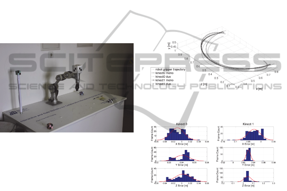
Our experimental setup (Figure 4) consists of two
Kinects connected directly to a single PC equipped
with an Intel Core i7-3770 quad core processor @
3.4 GHz running Ubuntu 12.04 LTS. The Kinects
were placed at an angle of 90° to each other about
2.5 meters away from the workspace. Four cubes
with a side length of 4 cm covered with a chessboard
ICINCO2014-11thInternationalConferenceonInformaticsinControl,AutomationandRobotics
614
pattern, which can easily be detected in the RGB
image, were used as calibration points. The RGB
and depth image of the Kinect are registered so that
the depth of the corresponding pixels can easily be
measured. From the coordinates of the four points
the transformation matrix for each Kinect can be
calculated. Compared to common chessboard based
stereo vision registrations algorithms this approach
has the advantages that it can be applied to settings
where the angle between the cameras is 90° degrees
or more and the calibration of each camera is
independent from the others. The downsides are that
it makes an exact placement of the reference cubes
necessary and the usage of only four points leads to
a high sensitivity against placement or measurement
errors.
Figure 4: Photograph of the Experimental Setup. The
robot arm is a Katana and the Kinects are stationed
directly in front of the arm (Kinect 1) and to the right
(Kinect 0), both out of view. The four calibration markers
can clearly be seen. The large cube on the Katana
represents an obstacle and is tracked by the workspace
monitor software.
To determine the calibration error measurements
with static objects at three points in the workspace
were made. The measured object is similar to the
cubes used for calibration but has a side length of 8
cm. Preliminary tests showed that the depth of
smaller objects cannot be reliably measured at the
given distance when there is no solid background. In
the worst case the mean error of 1960 samples was
5.0 cm with a standard deviation of 4 mm which
should roughly resemble the calibration error. The
measurements were done with one Kinect at a time
so that no interference could occur.
To determine the measurement accuracy on
continuously moving objects the cube was mounted
on a Katana robotic arm. The Katana was programed
to move between two points on a semi-circle
trajectory with one pass of the trajectory lasting 6.6
s. At 30 frames per second about 200 samples are
made throughout one pass. The measured trajectory
was estimated by a least squares approximation and
compared to the ideal robot trajectory (Figure 5).
First the measurements were made with only one
Kinect active leading to a worst case mean error of
4.4 cm with a standard deviation of 2.5 cm (Figure
6). In the second run, two Kinects were activated
which lead to a worst case mean error of 4.8 cm with
a standard deviation of 4.3 cm (Figure 7). The higher
deviation is caused by interference between the
Kinects. Through the higher computational load the
frame rate dropped to 24 fps in the second
measurement sequenced.
Figure 5: Obstacle Trajectories as Measured by Two
Perpendicular Kinects Compared to The Actual
Trajectory.
Figure 6: Measured Trajectory Error Distribution wrt.
Actual Trajectory when only one Kinect is active.
As a rough indicator of dimensions the main
author’s hand measures a spread of 25 cm. The work
by Mariotti postulated a coarse-grained obstacle
cube of side 33 cm. Marti’s (Marti) work recognises
the need for some thresholding when an actual
obstacle is located close to the boundary of two
coarse-grained obstacles so that both coarse-grained
obstacles are activated in this case, or not activated
when a certain distance between extremities of
obstacle coordinate and coarse-grained obstacle
boundary are detected.
The measurement results show that SLSC array
as workspace monitor is feasible with the coarse-
grained obstacle size of 33 cm and that the principle
RobotWorkspaceMonitoringwithRedundantStructuredLightCameras-APreliminaryInvestigation
615

of 2oo3 voting could also be used as each detected
coordinate would activate the same coarse grained
obstacle. It is however difficult to reliably detect
small objects (for instance a finger). Second an
accurate and robust calibration method for this class
of SLSC or other 3D cameras has to be established.
Third research effort should be expended on the
theme of a 3D camera who’s activation may be
synchronised to some external signal in order that
multiple cameras may monitor the same workspace
without interfering with each other.
Figure 7: Measured Trajectory Error Distribution wrt.
Actual Trajectory when both Kinects are active.
4 CONCLUDING
CONSIDERATIONS
4.1 Conclusions
This body of work sought to investigate two aspects
in robot workplace monitoring. The first is to
determine whether a detection of obstacles using a
cheap camera and optimised software is feasible
which, given the measured performance increase, we
believe is and thus further work in this direction is
warranted. We do not underestimate the work
required to bring the performance to a particular
standard considering the additional computational
expense required to subtract the robot arm from the
monitored picture nor in additional processing that
safety certification may require.
The second aim was to investigate the feasibility
of using redundant cheap sensors to monitor an area.
We believe whilst the error margins to a coarse
grained obstacle are small we believe that the
fundamental principle is workable and that further
investigation is warranted.
4.2 Future Work
Given our opinion that the basic methodology might
have industrial relevance we believe that an
estimation of the potential benefit in a
manufacturing environment needs to be determined.
Given that an emergency stop subtracts from robot
productivity (availability) which in a production
environment can be estimated, our work potentially
contributes to an increase in robot availability and
hence productivity. If this increase can be quantified,
a clear idea of the use cases which would benefit
from the work presented here ought to be gained
which in turn should serve to better focus further
research.
We are in two minds about the benefits in
dynamic path planning in such a use case. We see a
clear relationship between the size of the coarse-
grained obstacles and the reduction of volume (C
free
)
for a newly planned trajectory to occupy. Given that
the current path planning algorithm (Rapidly
exploring Random Tree as explained in LaValle)
may not converge forcing a robot into an emergency
stop resulting in loss of productivity we think that
pre-planned alternative trajectories could be
integrated into the initial job planning processes and
performed if the “main” trajectory is determined to
be unsafe. We judge the run-time computational
expense of such a strategy to be relatively small
therefore increasing the real-time response. Any
“available” computing time can then be invested in
more sophisticated detection algorithms. The pre-
planned trajectory also should increase the chances
of a production facility safety certification.
Finally up until now all our considerations have
been made on the assumption that an obstacle
appears out of nowhere which is not the case in real-
life. A real obstacle will be representable as a vector
with a trajectory of its own. This allows decisions to
be made on the basis of first and second derivatives.
If decisions are made on this basis then sensor
placement ought to focus towards the approach to
the work area rather than the core of the work area
were emergency stop as a response to an intrusion is
more likely. Further effort is need in this area.
ACKNOWLEDGEMENTS
Thanks are due to the School of Engineering, Zürich
University of Applied Science for their funding
contributions of the work presented here.
REFERENCES
ABB http://www.abb.com/product/seitp327/ec6cfad87f
69dd2dc12572d300775f5b.aspx last accessed 14th
ICINCO2014-11thInternationalConferenceonInformaticsinControl,AutomationandRobotics
616

March 2014
ANSI/RIA, ANSI R15.06-1999: American National
Standard for Industrial Robots and Robot Systems—
Safety Requirements. American National Standards
Institute/Robotics Industry Association, 1999.
Casa, S. “Personensicherer Betrieb von Robotern ohne
konventionelle Sicherheitsmassnahmen. MSc. Thesis.
InES, ZHAW, Winterthur Switzerland 2012.
Elshafie, M.; Bone, G. M., "Markerless human tracking
for industrial environments, "Electrical and Computer
Engineering, 2008. CCECE 2008. Canadian
Conference on, vol., no., pp.001139, 001144, 4-7 May
2008.
Graf, J.; Puls, S.; Worn, H., "Incorporating Novel Path
Planning Method into Cognitive Vision System for
Safe Human-Robot Interaction, "Future Computing,
Service Computation, Cognitive, Adaptive, Content,
Patterns, 2009. COMPUTATIONWORLD '09.
Computation World: vol., no., pp.443,447, 15-20 Nov.
2009.
Gall, H., "The TUV approach to functional safety
assessment and certification," Is Your Product Safe? -
IEE Seminar on (Ref. No. 2004/10724), vol., no.,
pp.29, 52, 16-16 Sept. 2004.
Hong L., Jie Z., "Motion planning for Human-Robot
Interaction based on stereo vision and SIFT, "Systems,
Man and Cybernetics, 2009. SMC 2009. IEEE
International Conference on, vol., no., pp.830,834, 11-
14 Oct. 2009.
Heyer, C., "Human-robot interaction and future industrial
robotics applications," Intelligent Robots and Systems
(IROS), 2010 IEEE/RSJ International Conference on,
vol., no., pp.4749,4754, 18-22 Oct. 2010.
Infante, M. L.; Kyrki, V., "Usability of force-based
controllers in physical human-robot
interaction," Human-Robot Interaction (HRI), 2011
6th ACM/IEEE International Conference on, vol., no.,
pp.355,362, 8-11 March 2011.
ISO, ISO 10218-1:2011: Robots and robotic devices
Safety requirements for industrial robots Part 1:
Robots. Geneva, Switzerland: International
Organization for Standardization, 2011.
ISO, ISO 10218-2:2011: Robots and robotic devices
Safety requirements for industrial robots Part 2: Robot
Systems and Integration. Geneva, Switzerland:
International Organization for Standardization, 2011.
Kulić, D., Croft, E., “Pre-collision safety strategies for
human-robot interaction”, Autonomous Robots,
Volume 22, Issue 2, pp 149-164, February 2007.
Lacevic, B.; Rocco, P.; Zanchettin, A. M., "Safety
Assessment and Control of Robotic Manipulators
Using Danger Field, "Robotics, IEEE Transactions on,
vol.29, no.5, pp.1257,1270, Oct. 2013.
LaValle, S., M. “Rapidly-Exploring Random Trees, A
New Tool for Path Planning” (1998).
http://citeseerx.ist.psu.edu/viewdoc/summary?doi=10.
1.1.35.1853 last accessed 04
th
July 2014.
Lenz, C.; Panin, G.; Roder, Thorsten; Wojtczyk, M.;
Knoll, A., "Hardware-assisted multiple object tracking
for human-robot-interaction," Human-Robot
Interaction (HRI), 2009 4th ACM/IEEE International
Conference on, vol., no., pp.283,284, 11-13 March
2009.
Lenz, C., Grimm, M., Röder, T., Knoll, A. „Fusing
multiple Kinects to survey shared Human-Robot-
Workspaces,” http://mediatum.ub.tum.de/attfile/1115
447/hd2/incoming/2012-Sep/934684.pdf last accessed
14th March 2014.
Lyons, R.E., Vanderkulk, W., “The Use of Triple-Modular
Redundancy to Improve Computer Reliability”, IBM
Journal, April 1962.
Mariotti, K. “A innovative robot motion planning
approach for real-time adaptations in a dynamic
working environment”. MSc. Thesis. InES, ZHAW,
Winterthur Switzerland 2013.
Marti, S. “Ein System zum Monitoring des dynamischen
Arbeitsraums eines Roboterarms”. Project Report.
InES, ZHAW, Winterthur Switzerland 2014.
Unpublished.
Najmaei, N.; Lele, S.; Kermani, M.R.; Sobot, R., "Human
factors for robot safety assessment," Advanced
Intelligent Mechatronics (AIM), 2010 IEEE/ASME
International Conference on , vol., no., pp.539,544, 6-
9 July 2010.
OpenNI http://www.openni.org last accessed 14th March
2014.
OpenCV http://opencv.org/ last accessed 14th March
2014.
OpenGL http://www.opengl.org/ last accessed 14th March
2014.
Pilz http://www.pilz.com/de-CH/company/news/sub/
products/articles/05525 last accessed 14th March
2014.
Schmidhauser, E., Müller, R., Hüppi, R. „JILAS - Jig-Less
Airplane Assembly Montage in Kleinserien durch
Mensch-Roboter-Interaktion“ Internationales Forum
Mechatronik 2012, Proceedings of, ISBN: 978-3-200-
02777-0, Mayrhofen, 21 - 22. November 2012.
Vasic, M.; Billard, A., "Safety issues in human-robot
interactions," Robotics and Automation (ICRA), 2013
IEEE International Conference on, vol., no., pp.197,
204, 6-10 May 2013.
Zanchettin, A. M.; Rocco, P., "Path-consistent safety in
mixed human-robot collaborative manufacturing
environments," Intelligent Robots and Systems (IROS),
2013 IEEE/RSJ International Conference on, vol., no.,
pp.1131,1136, 3-7 Nov. 2013.
RobotWorkspaceMonitoringwithRedundantStructuredLightCameras-APreliminaryInvestigation
617
