
SPHERA
A Unifying Structure from Motion Framework for Central Projection Cameras
Christiano Couto Gava
1,2
and Didier Stricker
1,2
1
Department Augmented Vision, German Research Center for Artificial Intelligence, Kaiserslautern, Germany
2
Department of Informatics, Technical University of Kaiserslautern, Kaiserslautern, Germany
Keywords:
Spherical Images, Structure from Motion, Central Projection Cameras, 3D Reconstruction.
Abstract:
As multi-view reconstruction techniques evolve, they accomplish to reconstruct larger environments. This is
possible due to the availability of vast image collections of the target scenes. Within the next years it will
be necessary to account for all available sources of visual information to supply future 3D reconstruction
approaches. Accordingly, Structure from Motion (SfM) algorithms will need to handle such variety of image
sources, i.e. perspective, wide-angle or spherical images. Although SfM for perspective and spherical images
as well as catadioptric systems have already been studied, state of the art algorithms are not able to deal with
these images simultaneously. To close this gap, we developed SPHERA, a unifying SfM framework designed
for central projection cameras. It uses a sphere as underlying model, allowing single effective viewpoint vision
systems to be treated in a unified way. We validate our framework with quantitative evaluations on synthetic
spherical as well as real perspective, spherical and hybrid image datasets. Results show that SPHERA is a
powerful framework to support upcoming algorithms and applications on large scale 3D reconstruction.
1 INTRODUCTION
The popularity of full panoramic images has signif-
icantly increased during the past few years. This
is confirmed by the variety of spherical image ac-
quisition hardware and software packages available
nowadays (Civetta, 2009), (LizardQ, 2014), (Seitz-
Roundshot, 2014), (PTgui-Pro, 2014). Another rea-
son for the increased popularity of such images is the
possibility to create immersive environments where
the user experiences a first-person view, such as
Google Street View (Anguelov et al., 2010). Full
spherical images are specially attractive for this kind
of visualization as well as 3D reconstruction of large
scenes. These applications find appliance in doc-
umentation, education, preservation of cultural her-
itage, gaming, city planing, etc. Applications based
on multi-view reconstruction usually require the ac-
quisition of several images to produce a 3D model
of the target scene. Hence, they implicitly demand
Structure from Motion (SfM) to recover the cameras’
poses before the 3D model can be computed.
Spherical images are also more suitable for SfM
than standard perspective images. Due to their wide
field of view, scene features are observed in more im-
ages, thus increasing the number of constraints on
cameras’ poses. Consequently, methods have been
derived to perform SfM on wide field of view cam-
eras. More specifically, (Chang and Hebert, 2000),
(Micusik and Pajdla, 2006), (Bagnato et al., 2011) ad-
dress SfM on omnidirectional images, while (Kangni
and Laganiere, 2007), (Pagani and Stricker, 2011),
(Aly and Bouguet, 2012) deal with full spherical im-
ages. Not surprisingly, perspective SfM has been ex-
tensively studied e.g. by (Snavely et al., 2006), (Hart-
ley and Zisserman, 2004), (Ma et al., 2003). Although
these approacheshave shown to work well for the spe-
cific image type they were designed for, up to the au-
thors knowledge they are unable to handle images of
any other type.
Given the current effort to reconstruct ever grow-
ing environments (Agarwal et al., 2009), (Furukawa
et al., 2010) every source of visual information shall
be taken into account, regardless of the shape of im-
age surface. This is an issue that has not yet being
addressed. Apart from performance and accuracy, an-
other highly desirable feature of 3D reconstruction al-
gorithms is to update and improve the scene model
whenever new images are available. Here again, the
ability to deal with different camera types is essential.
Therefore, we present SPHERA, a novel Structure
from Motion framework to bridge the gap between
285
Gava C. and Stricker D..
SPHERA - A Unifying Structure from Motion Framework for Central Projection Cameras.
DOI: 10.5220/0005301702850293
In Proceedings of the 10th International Conference on Computer Vision Theory and Applications (VISAPP-2015), pages 285-293
ISBN: 978-989-758-091-8
Copyright
c
2015 SCITEPRESS (Science and Technology Publications, Lda.)

current SfM methods for central projection cameras.
We build on the model proposed in (Geyer and Dani-
ilidis, 2001) and adopt the unit sphere to represent im-
ages and to treat heterogeneous camera types in an
unified way. Our approach dynamically selects the
best information available to recover camera poses
and scene structure. Experiments on synthetic and
real image sequences validate our framework as a
valuable contribution to support large scale 3D recon-
struction algorithms.
Related Work
The work presented in (Chang and Hebert, 2000) uses
epipolar geometry to compute scene structure from
an omnidirectional vision system mounted on a robot
platform. However, the camera pose problem is not
addressed. In (Micusik and Pajdla, 2006), the au-
thors focus on omnidirectional images with a field of
view larger than 180
o
and devise a camera model spe-
cific for that type of image. Although scene struc-
ture can be recovered, the technique is limited to the
two-view geometry problem. Consequently, the pro-
posed camera model can hardly be used in a more
generic SfM approach. In (Bagnato et al., 2011), the
authors present a variational approach to achieve ego-
motion estimation and 3D reconstruction from om-
nidirectional image sequences. Nonetheless, the en-
vironment must be densely sampled so that the re-
lationship between image derivatives and 3D motion
parameters is still valid. Thus, this approach can not
be used in a more general, sparse SfM.
A method to recover camera poses from a set of
spherical images on a sparsely sampled environment
is presented in (Kangni and Laganiere, 2007). How-
ever, SfM is performed based on panoramic cubes
computed for each spherical image. That is, the cam-
era poses are recovered by casting the spherical prob-
lem back to the standard perspective problem. In
(Aly and Bouguet, 2012), spherical images are used
to estimate the relative camera poses and to build a
map of the environment. To simplify the problem,
Aly and Bouguet assume planar motion, i.e. all cam-
era frames lie on the same plane. This assumption
strongly limits the applicability of the proposed tech-
nique. Finally, our approach is closely related to (Pa-
gani and Stricker, 2011), as both exploit full spherical
images to deliver a sparse representation of the scene
along with recovered camera poses. Nevertheless, the
method presented in (Pagani and Stricker, 2011) was
designed exclusively for spherical cameras, whereas
our framework naturally handles any kind of central
projection camera.
2 BACKGROUND
2.1 Spherical Images
A spherical image is a 180
o
×360
o
environment map-
ping that allows an entire scene to be captured from
a single point in space. Consequently, every visible
3D point P
W
given in world coordinate system can be
mapped onto the image surface. This is done by a
two-step process. First, analogue to the perspective
case, P
W
is represented in the camera coordinate sys-
tem as P
C
= RP
W
+ t, with R and t representing the
camera rotation matrix and translation vector. Sec-
ond, and different from the perspective projection, P
C
is projected onto the image surface by scaling its coor-
dinates, as shown in Fig. 1-(a). Without loss of gen-
erality, we assume a unit sphere. Thus, the scaling
becomes a normalization and p = P
C
/kP
C
k.
Spherical images are stored as a 2D pixel-map as
depicted in Fig. 1-(b). This map is obtained using a
latitude-longitude transformation, with 0 ≤ φ ≤ π and
0 ≤ θ ≤ 2π.
(a) (b)
Figure 1: (a) Spherical coordinates and illustration of the
spherical projection. (b) Pixel-map of a spherical image.
2.2 Sphere as Unifying Model
Our approach is grounded on the seminal work de-
veloped in (Geyer and Daniilidis, 2001), where the
authors proposed a unifying model for the projective
geometry of vision systems having a single effective
viewpoint. These vision systems are commonly re-
ferred to as central projection cameras and include
catadioptric sensors featuring conic mirrors of differ-
ent shapes, such as parabolic, hyperbolic or elliptic.
Geyer and Daniilidis showed that any central cata-
dioptric projection is equivalent to a two-step map-
ping via the sphere. It is well known from the pin-
hole model that standard perspective imaging charac-
terizes a single viewpoint system. Nonetheless, per-
spective images are also central catadioptric systems
with a virtual planar mirror and are, therefore, covered
by the aforementioned model. In practice, that means
it is possible to treat these central projection systems
as spherical cameras, provided the mapping from the
original image surface to the sphere is known. This
mapping may be seen as a warping transformation
VISAPP2015-InternationalConferenceonComputerVisionTheoryandApplications
286

from the original image to the unit sphere. As an ex-
ample, Fig. 2 shows the result of warping a perspec-
tive image onto the sphere.
(a) (b)
Figure 2: Example of (a) an original perspective im-
age (Strecha et al., 2008) and (b) its warped version. The
warped image appears mirrored due to the viewpoint (“out-
side” the unit sphere).
2.3 Spherical Camera Pose Estimation
2.3.1 Epipolar Geometry
The epipolar geometry for full spherical cameras has
already been presented in (Torii et al., 2005). Thus,
here we provide a short overview. Consider a pair
of spherical cameras C
0
and C
1
. Let R and t be the
associated rotation matrix and translation vector. A
point p
0
on the surface ofC
0
, along with the centers of
the cameras, define a plane Π that may be expressed
by its normal vector n
Π
= Rp
0
× t = [t]
×
Rp
0
, where
[t]
×
is the skew-symmetric matrix representing the
cross-product. For any point p
1
on C
1
belonging to
Π the condition p
T
1
n
Π
= 0 holds, which is equivalent
to p
T
1
[t]
×
Rp
0
= 0, where E = [t]
×
R is the essential
matrix (Hartley and Zisserman, 2004). The condition
p
T
1
Ep
0
= 0 is known as the epipolar constraint and is
the same result obtained in the perspective case. This
shows that the epipolar constraint is independent of
the shape of the image surface.
n
Π
C
0
p
0
,
t
R
1
C
p
1
Π
Figure 3: Epipolar geometry for two spherical images.
2.3.2 Pose Estimation
There are mainly two techniques for computing cam-
era poses. The first is useful for relative pairwise
pose estimation, typically when only 2D image cor-
respondences (2D-2D correspondences)are available.
Without loss of generality, one of the cameras is as-
sumed as reference and R and t represent the pose of
the second camera. In this case, R and t may be de-
termined with e.g. the 5-point algorithm (Stew´enius
et al., 2006). The second technique is normally used
when a number of 3D scene points and their respec-
tive projections onto an image are known, i.e. a set of
2D-3D correspondences is available. This configures
a Perspective-n-point (PnP) problem, which can be
solved with a minimum of 6 correspondences (Quan
and Lan, 1999).
3 THE PROPOSED APPROACH
Given a set of images of a scene, our goal is to ac-
curately estimate the pose of all cameras as well as
to recover a sparse 3D point cloud of the underlying
scene representing its geometry. The set of central
projection cameras is then defined as
C =
C
j
=
ˆ
R
j
|
ˆ
t
j
|
ˆ
R
j
∈ SO(3),
ˆ
t
j
∈ R
3
, (1)
where j = 0,..,M − 1, M is the total number of cam-
eras and
ˆ
R
j
and
ˆ
t
j
are the rotation matrix and trans-
lation vector representing the estimated pose of cam-
era C
j
. To aid the non-linear optmization, we adopt
an axis-angle parameterization for the rotation matrix
and C
j
is then parameterized by a vector ρ
j
∈ R
6
. All
together, the cameras are parameterized by a vector
ρ ∈ R
m
, with m = 6M.
Likewise, we denote the set of sparse 3D points
reconstructed along with the camera poses as
P =
ˆ
P
i
∈ R
3
, (2)
where i = 0, ..,N − 1, N is the number of points and
ˆ
P
i
holds the estimated coordinates of a scene point P
i
.
We then formulate the problem of recovering all
cameras’ poses along with a sparse point representa-
tion of the scene as a non-linear optimization prob-
lem. More precisely, the parameter vector ρ is opti-
mized in order to minimize
min
ρ
N−1
∑
i=0
M− 1
∑
j=0
f
ij
(ρ), (3)
where f
ij
(ρ) is a cost function for each point
ˆ
P
i
and
camera C
j
. The parameters ρ
+
that minimize Eq. 3
are the sought camera poses. Then, ρ
+
is used to up-
date the points
ˆ
P
i
to obtain the sparse scene represen-
tation.
3.1 Reprojection Error
The reprojection error of a point
ˆ
P
i
on camera C
j
is
computed as
e
ij
(ρ) = cos
−1
(p
ij
ˆp
ij
), (4)
where p
ij
ˆp
ij
is the scalar product between the ex-
pected projection p
ij
and the measured projection ˆp
ij
SPHERA-AUnifyingStructurefromMotionFrameworkforCentralProjectionCameras
287

obtained with
ˆ
P
i
,
ˆ
R
j
and
ˆ
t
j
. The expected projec-
tion p
ij
is determined by the keypoint location corre-
sponding to P
i
. Note that as −1≤ p
ij
ˆp
ij
≤ 1, we have
0 ≤ e
ij
(ρ) ≤ π and it is not necessary to take the ab-
solute value in Eq. 4. Furthermore, we do not use any
approximation of the reprojection error as in (Pagani
and Stricker, 2011). As we aim at high accuracy, the
error defined in Eq. 4 is the exact geodesic distance,
i.e. the exact angular deviation, between p
ij
and ˆp
ij
.
Together, all reprojection errors of a given
ˆ
P
i
∈ P may
be expressed as a vector e
i
(ρ) ∈ R
M
. Additionally, to
each point P
i
we associate a visibility map
V
i
=
(C
j
, p
ij
) | C
j
∈ C , p
ij
∈ S
2
, (5)
where S
2
represents the unit sphere. We denote the
pair (C
j
, p
ij
) as the observation of a scene point P
i
on
camera C
j
. The existence of (C
j
, p
ij
) implies that P
i
is visible on camera C
j
. Taking the visibility map into
account allows to reduce the dimensionality of e
i
(ρ)
from M to |V
i
|, where |V
i
| is the number of observa-
tions of P
i
. Consequently, the dimensionality of e
i
(ρ)
is no longer fixed. Instead, it is adapted to the visibil-
ity of the corresponding point P
i
.
3.2 Minimizing the Reprojection Error
Finding the camera poses and scene structure as de-
scribed above can be achieved by solving a bundle
adjustment problem (Triggs et al., 1999), i.e. by min-
imizing the reprojection error with respect to all ex-
isting 3D points. This allows us to rewrite Eq. 3 in
the form shown in Eq. 6. However, different from
the classical bundle adjustment, we do not consider
the 3D point coordinates as parameters to optmize.
Instead, only the camera parameters are used. This
leads to two important advantages. First, the dimen-
sion of the parameter search space is strongly re-
duced, simplifying and speeding up non-linear refine-
ment. Second, the set of 3D points used to solve Eq. 6
may be dynamically changed, allowing to use only the
best, consistent, points.
min
ρ
N−1
∑
i=0
M− 1
∑
j=0
γ
ij
e
ij
(ρ), γ
ij
=
1, if C
j
∈ V
i
0, otherwise
(6)
In practice, we use (Agarwal et al., 2010) as the
core non-linear solver upon which SPHERA is built.
In addition, we solve a modified version of Eq. 6,
where only the most reliable points are used. These
points are defined as
P
∗
=
ˆ
P
i
∈ P | e
ij
(ρ) < τ, ∀(C
j
, ˆp
ij
) ∈ V
i
, (7)
where τ is a threshold imposed to all individual repro-
jection errors e
ij
(ρ).
4 EVALUATION
4.1 Preliminaries
Keypoints are detected and matched using the method
proposed in (Gava et al., 2013), where a multi-scale
keypoint detector and matcher was developed for
high resolution spherical images. Nonetheless, it is
worth mentioning that SPHERA is completely inde-
pendent of how keypoints are detected, described and
matched. Consequently, any other keypoint detector
and matcher may be adopted (see Section 4.3).
We validate our framework using synthetic spher-
ical as well as real perspective and spherical images.
The resolution of all spherical images presented be-
low is 14142× 7071 (100 Mega-pixels). Experiments
are divided into four categories: The first category
consists of a set of synthetic spherical cameras where
the goal is to validate our framework on spherical im-
ages using groundtruth. The second is composed ex-
clusively of real perspective images. Here, the idea
is to show that our framework is suitable for standard
SfM, i.e. it may be used even when no spherical im-
age is available. The third category consists of spheri-
cal images only, where we compared SPHERA to the
work presented in (Pagani and Stricker, 2011) in two
different real world scenarios. The fourth and last cat-
egory is a hybrid dataset, i.e. real perspective and
spherical images are used simultaneously. The aim
is to demonstrate SPHERA’s ability to improve scene
geometry estimation whenevermore images are avail-
able, independent of their types
1
. Whenever avail-
able, groundtruth data is used for evaluation. Oth-
erwise, we rely on the global mean reprojection er-
ror computed taking all images and all reconstructed
points into account.
4.2 Synthetic Dataset
An artificial room with flat walls and dimensions
4x4x3 meters was created using (Blender, 2014) and
9 spherical images were rendered (see Fig. 4-(a)).
The poses of these artificially generated cameras were
used as groundtruth. Additionally, the depth map
shown in Fig. 4-(b) was stored and serves to measure
the accuracy of the recovered scene geometry.
After detecting and matching keypoints with
Gava’s approach, camera poses and scene structure
were recovered with SPHERA. Residual errors were
computed in the following way. The position error is
the Euclidean distance between the groundtruth and
estimated camera positions. To measure the orienta-
tion error, we chose a function presented in (Huynh,
1
Assuming central projection cameras.
VISAPP2015-InternationalConferenceonComputerVisionTheoryandApplications
288
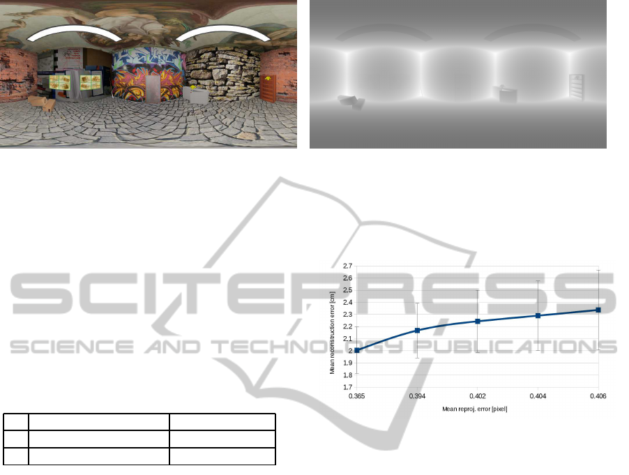
(a) (b)
Figure 4: (a) Sample image of the synthetic dataset. (b) Groundtruth depth map used to evaluate the accuracy of scene
geometry estimation (contrast enhanced to improve visualization).
2009) and defined as klog
R
ˆ
R
T
k, with R the desired
rotation and
ˆ
R the estimated rotation matrix. This is a
metric in SO(3) and can be efficiently computed with
quaternions. For details we refer to (Huynh, 2009).
Table 1 summarizes the errors in camera pose estima-
tion for . Although very small, these values are not
zero mainly due to the precision of detected keypoint
locations.
Table 1: Errors in camera pose estimation for the synthetic
dataset. Mean and standard deviation are identified by µ and
σ, respectively.
orient. error [degree] pos. error [cm]
µ 6.72× 10
−5
1.92× 10
−3
σ 1.73× 10
−4
3.2× 10
−3
Here, we also evaluated the influence of the ac-
cepted reprojection error τ (see Eq. 7) on the re-
covered camera poses and scene structure. We re-
peated the experiment varying τ within the interval
[τ
min
,τ
max
]. Although τ is an angular deviation, for
convenience values are converted and presented in
pixels. We chose τ
min
and τ
max
to be equivalent to
1 and 5 pixels, respectively.
We noticed that the impact of varying τ on cam-
era pose estimation was neglectable, i.e. the values
presented in Table 1 remained constant in practice.
This happens due to the fact that, although τ varies
by a factor of 5, the global mean reprojection er-
ror remains in the interval [0.365, 0.406] pixels (see
Fig. 5). However, the same does not hold for the re-
covered scene structure and deserves attention. We
compute the residual error of a reconstructed point
ˆ
P
i
as k
ˆ
P
i
− P
i
k, where the coordinates of P
i
are obtained
as follows. A virtual spherical camera is located at
the origin of the global coordinate system. The pro-
jection of
ˆ
P
i
onto this virtual camera delivers p
′
i
. Then
P
i
= I
dm
p
′
i
p
′
i
, where I
dm
p
′
i
is the groundtruth
depth retrieved from the stored depth map. Not sur-
prisingly, the accuracy of the recovered scene geome-
try correlates with the mean reprojection error, as de-
picted in Fig. 5.
Figure 5: Influence of the mean reprojection error on the
accuracy of recovered scene geometry. Vertical bars show
the respective standard deviations scaled down by a factor
of 10. Values were computed using all reconstructed points
(over 30 thousand).
4.3 Perspective Datasets
To validate our approach on perspective images, we
compared it to Bundler (Snavely et al., 2006), a pop-
ular software developed for SfM on standard perspec-
tive images. Bundler is the camera calibration tool
currently used in (Furukawaand Ponce, 2008), (Agar-
wal et al., 2009), (Furukawa et al., 2010) and is pub-
licly available.
The experiments presented in this section were
carried out on the datasets published in (Strecha et al.,
2008). For each dataset, we ran Bundler on the
original images and SPHERA on the corresponding
warped images as shown in Fig. 2. To ensure a fair
comparison, we ran our pipeline using the same key-
points detected by Bundler (Lowe, 2004) after warp-
ing their coordinates to the unit sphere. This elimi-
nates the influence of image feature location on the
evaluation. Moreover, it shows SPHERA’s indepen-
dence of keypoint detectors as pointed out in Sec-
tion 4.1. Results on camera pose estimation are
summarized in Fig. 6. Orientation errors were ob-
SPHERA-AUnifyingStructurefromMotionFrameworkforCentralProjectionCameras
289
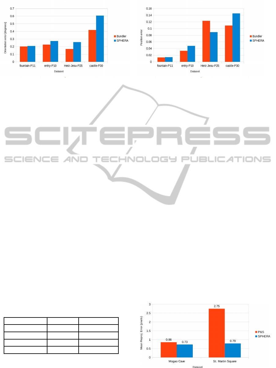
(a) (b)
Figure 6: (a) Orientation error and (b) position error on perspective image datasets obtained with Bundler and SPHERA. See
text for details.
tained as in the previous section. Position errors,
however, were computed after preprocessing the es-
timated camera positions. To account for the differ-
ences in scale, the baseline between the closest cam-
era pair was normalized and the remaining camera po-
sitions were scaled accordingly. After that, the Eu-
clidean distance was measured as in Section 4.2.
As can be seen, Bundler performs slightly better
and the reason is as follows. Bundler works exclu-
sively on perspective images and optimizes the cam-
era poses along with their individual intrinsic param-
eters such as focal length and lens distortion. In
contrast, SPHERA has been designed to operate on
any kind of central projection camera, but the opti-
mization of intrinsic parameters has not been inte-
grated yet. Therefore, for the experiments presented
in this section, we used a constant focal length in
our pipeline and a variable focal length for Bundler.
In fact, the differences observed in Fig. 6 are pro-
portional to the variance of the focal length within
each dataset, see Table 2. The exception is Herz-Jesu-
P25, where Bundler delivers smaller orientation error
whereas SPHERA provides better camera positions.
Table 2: Variation of focal lengths estimated with Bundler.
The second column shows the standard deviation and the
third column the difference between maximum and min-
imum values. Note that, except for the Herz-Jesu-P25
dataset, the differences in Fig. 6 are proportional to the vari-
ation of the focal length.
dataset σ
f
[pixel] range [pixel]
fountain-P11 8.49 23.02
entry-P10 10.97 28.41
Herz-Jesu-P25 4.01 16.15
castle-P30 20.44 118.86
4.4 Spherical Datasets
In this section we compare SPHERA and the ap-
proach presented in (Pagani and Stricker, 2011). We
ran both pipelines on two datasets. The first dataset
consists of 9 spherical images captured inside one
of the Mogao Caves, in China. The second dataset
contains 35 spherical images taken at the Saint Mar-
tin Square in Kaiserslautern, Germany, and represents
outdoors, more challenging, environments. Due to the
lack of groundtruth data for these datasets, we based
our evaluation on the global mean reprojection er-
ror. The assumption is that the correlation observed
in Section 4.2 can be used to infer the relative accu-
racy of the estimated scene geometry.
As can be seen in Fig. 7, SPHERA improves the
reprojection error on both datasets, specially on the
St. Martin Square. In the case of the Mogao Cave, due
to its simple geometry and rich texture (Fig. 8-(a)),
only few points are discarded based on Eq. 7, what
explains the small difference in the reprojection error
for this dataset. The St. Martin Square dataset is more
challenging (Fig. 8-(b)). It contains many low tex-
tured regions, depth discontinuites, occlusions as well
as repetitive patterns. Therefore, several points are in-
consistent and discarding them from the camera pose
estimation leads to the difference observed in Fig. 7.
These results suggest that SPHERA delivers more ac-
curate scene structures. Figure 8 displays the sparse
point clouds yielded by our framework, where details
of the surroundings are accurately reconstructed.
Figure 7: Global mean reprojection error on spherical im-
age datasets obtained with (Pagani and Stricker, 2011) and
SPHERA. See text for details.
VISAPP2015-InternationalConferenceonComputerVisionTheoryandApplications
290
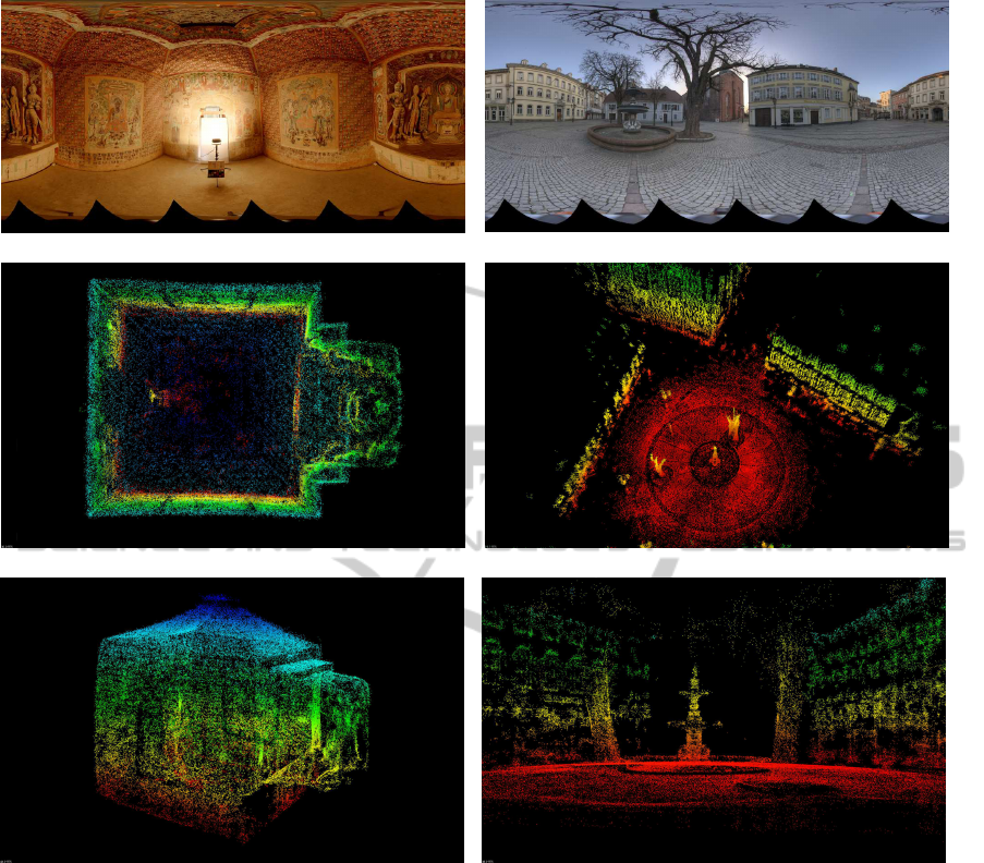
(a) (b)
(c) (d)
(e) (f)
Figure 8: First row: Sample images of the Mogao Cave and St. Martin Square datasets. Second and third rows: reconstructed
point clouds delivered by SPHERA, containing approximately 106000 and 197000 3D points for the Mogao Cave and St.
Martin Square, respectively.
4.5 Hybrid Dataset
In this section we evaluate the SPHERA framework
on a hybrid dataset composed of perspective and
spherical images. The idea is to show that our frame-
work naturally handles different central projection
cameras simultaneously. This dataset is composed
of the same 35 spherical images used in the previ-
ous experiment and additional 11 perspective images
of resolution 3888× 2592 pixels. As shown in Fig. 9,
the reprojection error obtained with spherical images
(same as previous experiment) is better than the error
for perspective images.
The main reason spherical camera pose estima-
tion is better than its perspective counterpart is due to
their wide field of view. As can be seen in Fig. 10,
matches between spherical images cover the entire
scene and thus impose more constraints on cameras’
poses. As expected, the reprojection error decreases
when perspective and spherical images are used si-
multaneously.
5 CONCLUSIONS
This paper presents SPHERA, a novel unifying Struc-
ture from Motion framework designed for central pro-
jection cameras. The goal is to cover the gaps be-
SPHERA-AUnifyingStructurefromMotionFrameworkforCentralProjectionCameras
291
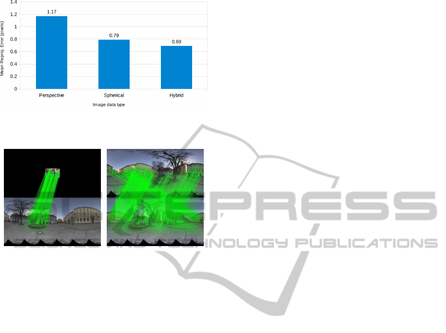
Figure 9: Global mean reprojection error for the hybrid St.
Martin Square experiment. Note how it decreases when per-
spective and spherical images are used together.
(a) (b)
Figure 10: (a) Symmetric matches between a warped per-
spective image and a spherical image. Matches are drawn
on their corresponding pixel maps to ease visualization. (b)
Symmetric matches between two full spherical images.
tween algorithms developed for perspective,spherical
and catadioptric images. Through extensive quantita-
tive evaluation on synthetic and real image sequences,
we showed that our approach delivers high quality
camera pose as well as scene geometry estimations
when compared to state of the art approaches opti-
mized for specific camera types.
Future work aims at integrating the optimization
of intrinsic parameters to increase the accuracy of
perspective cameras pose estimation. Additionally,
we plan to validate our framework on larger, hybrid
image datasets, supported by groundtruth data. Fi-
nally, SPHERA will be the underlying SfM mecha-
nism in our upcoming dense multi-view reconstruc-
tion approach.
ACKNOWLEDGEMENTS
This work was funded by the project DENSITY
(01IW12001). The authors would like to thank
Richard Schulz for the creation of the synthetic
dataset.
REFERENCES
Agarwal, S., Mierle, K., and Others (2010). Ceres solver.
https://code.google.com/p/ceres-solver/.
Agarwal, S., Snavely, N., Simon, I., Seitz, S. M., and
Szeliski, R. (2009). Building rome in a day. In ICCV,
pages 72–79, Kyoto, Japan.
Aly, M. and Bouguet, J.-Y. (2012). Street view goes in-
doors: Automatic pose estimation from uncalibrated
unordered spherical panoramas. In WACV, pages 1–8.
IEEE.
Anguelov, D., Dulong, C., Filip, D., Frueh, C., Lafon,
S., Lyon, R., Ogale, A., Vincent, L., and Weaver, J.
(2010). Google street view: Capturing the world at
street level. Computer, 43.
Bagnato, L., Frossard, P., and Vandergheynst, P. (2011). A
Variational Framework for Structure from Motion in-
Omnidirectional Image Sequences. Journal of Math-
ematical Imaging and Vision, 41(3):182–193.
Blender (2014). http://www.blender.org/. Retrieved Octo-
ber 19, 2014.
Chang, P. and Hebert, M. (2000). Omni-directional struc-
ture from motion. In OMNIVIS, Washington, DC,
USA. IEEE Computer Society.
Civetta (2009). http://www.weiss-ag.org/solutions/civetta/.
Retrieved October 16, 2014.
Furukawa, Y., Curless, B., Seitz, S. M., and Szeliski, R.
(2010). Towards internet-scale multi-view stereo. In
CVPR.
Furukawa, Y. and Ponce, J. (2008). Accurate, dense, and
robust multi-view stereopsis. IEEE Transactions on
Pattern Analysis and Machine Intelligence, 01(01):1–
14.
Gava, C. C., Hengen, J.-M., Taetz, B., and Stricker, D.
(2013). Keypoint detection and matching on high res-
olution spherical images. In ISVC, pages 363–372,
Rethymnon, Crete, Greece.
Geyer, C. and Daniilidis, K. (2001). Catadioptric projective
geometry. Int. Journal of Computer Vision, 43:223–
243.
Hartley, R. I. and Zisserman, A. (2004). Multiple View Ge-
ometry in Computer Vision. Cambridge University
Press, ISBN: 0521540518, second edition.
Huynh, D. Q. (2009). Metrics for 3d rotations: Comparison
and analysis. Journal of Mathematical Imaging and
Vision, 35(2):155–164.
Kangni, F. and Laganiere, R. (2007). Orientation and pose
recovery from spherical panoramas. ICCV, 0:1–8.
LizardQ (2014). http://www.lizardq.com. Retrieved Octo-
ber 16, 2014.
Lowe, D. G. (2004). Distinctive image features from scale-
invariant keypoints. Int. Journal of Computer Vision,
60:91–110.
Ma, Y., Soatto, S., Kosecka, J., and Sastry, S. (2003). An in-
vitation to 3D vision, from images to models. Springer
Verlag.
Micusik, B. and Pajdla, T. (2006). Structure from motion
with wide circular field of view cameras. IEEE Trans.
Pattern Anal. Mach. Intell., 28(7):1135–1149.
VISAPP2015-InternationalConferenceonComputerVisionTheoryandApplications
292

Pagani, A. and Stricker, D. (2011). Structure from motion
using full spherical panoramic cameras. In OMNIVIS.
PTgui-Pro (2014). New house internet services b.v.
http://www.ptgui.com. Retrieved October 16, 2014.
Quan, L. and Lan, Z. (1999). Linear n-point camera pose
determination. IEEE Trans. Pattern Anal. Mach. In-
tell., 21(8):774–780.
Seitz-Roundshot (2014). http://www.roundshot.ch. Re-
trieved October 16, 2014.
Snavely, N., Seitz, S. M., and Szeliski, R. (2006). Photo
tourism: exploring photo collections in 3D. In ACM
SIGGRAPH 2006 Papers, SIGGRAPH, pages 835–
846, New York, NY, USA. ACM.
Stew´enius, H., Engels, C., and Nist´er, D. (2006). Recent
developments on direct relative orientation. Journal
of Photogrammetry and Remote Sensing, 60:284–294.
Strecha, C., von Hansen, W., Van Gool, L., Fua, P., and
Thoennessen, U. (2008). On Benchmarking Camera
Calibration and Multi-View Stereo for High Resolu-
tion Imagery. In Proceedings of the IEEE Conference
on Computer Vision and Pattern Recognition.
Torii, A., Imiya, A., and Ohnishi, N. (2005). Two- and
Three- View Geometry for Spherical Cameras. In
OMNIVIS.
Triggs, B., Mclauchlan, P. F., Hartley, R. I., and Fitzgibbon,
A. W. (1999). Bundle adjustment: A modern synthe-
sis. In Proc. of the International Workshop on Vision
Algorithms: Theory and Practice, pages 298–372.
SPHERA-AUnifyingStructurefromMotionFrameworkforCentralProjectionCameras
293
