
LARES-lab: A Thermo-vacuum Facility for Research and e-Learning
Tests of LARES Satellite Components and Small Payloads for e-Learning
A. Paolozzi
1,2,4
, I. Ciufolini
3,4
, C. Paris
2,4
and G. Sindoni
2
1
Scuola di Ingegneria Aerospaziale, Sapienza University of Rome, Via Salaria 851, 00138, Roma, Italy
2
Dipartimento DIAEE, Sapienza University of Rome, Via Eudossiana 18, 00184, Roma, Italy
3
Dipartimento di Ingegneria dell’Innovazione, University of Salento, Via per Monteroni, 73100, Lecce, Italy
4
Centro Fermi, Via Panisperna 89, 00184, Rome, Italy
Keywords: Thermo-vacuum Testing, Space Simulator, e-Learning, LARES.
Abstract: LARES, an Italian Space Agency satellite, has been successfully launched in 2012. A small thermo-vacuum
facility has been specifically designed and built for testing the optical components of the satellite in
simulated space environment. Due to the extremely demanding performances of LARES satellite, the
facility has been built using the most up-to-date technology available. In particular Sun, Earth and deep
space can be simulated in a ultra high vacuum. When the tests connected with the LARES mission reduced,
it was decided to devote the thermo-vacuum chamber also to didactic activities. The facility was designed to
be operated remotely only for some basic operations. The full automation of the facility is in progress in
order to provide the students and the researchers with easy and long term access, including also the
possibility to operate remotely from the internet and perform complex tests. The students will then have a
big opportunity to learn in practice all the aspects of thermo-vacuum testing, which are of paramount
importance in the space industry. It will be possible to perform thermal tests from either the classroom or
home, by exposing the specimen for a specified amount of time, toward Earth, Sun or deep space
simulators. They will collect pressures and temperatures and will input additional thermal power through
resistive heaters. The paper will first describe the facility and its capabilities showing the tests performed on
the LARES satellite components, then will focus mainly on the planned upgrades that will improve its
remote use both for research and e-learning.
1 INTRODUCTION
The Italian Space Agency (ASI) supported the
LARES mission (Ciufolini, 2011) including, among
other things, the design (Paolozzi, 2011) and the
construction (Paolozzi, 2009) of a 400 kg satellite
for testing “frame-dragging” (Ciufolini, 2007),
predicted by General Relativity. On the 13th
February 2012 the new ESA launcher VEGA
inserted perfectly in orbit LARES (Paolozzi, 2013),
the main payload, and eight small satellites built by
different universities. It was an outstanding result
considering that it was an inaugural flight, initially
devoted exclusively for qualifying this new
launcher. In 2008 ASI proposed to ESA to add a
further objective to this launch: contribute to
fundamental physics (Ciufolini, 2013a) with a very
reliable satellite. Despite the increase of complexity
of the qualification launch, ESA accepted, being also
responsive, through its educational office, towards
the university requests and allowing on board eight
more payloads.
Indeed a measurement of frame dragging with an
accuracy of about 10% was already obtained
(Ciufolini, 2004) (Ries, 2011) with the two
LAGEOS satellites. But, as anticipated in several
papers over the years (Ciufolini, 1996), with the use
of a combination of three satellites, the LAGEOS
satellites plus LARES (Ciufolini, 2003), it will be
possible to improve by one order of magnitude the
accuracy of the measurement (Ciufolini, 2012)
(Ciufolini, 2013b).
During the development of the LARES program
a critical issue arose whether it was necessary to
passively control the satellite temperature by
painting it (Paolozzi, 2012a): a high temperature of
the satellite body could both spoil the Cube Corner
Reflectors (CCRs) and increase the thermal thrust
(Bosco, 2007). Unfortunately the thermo-optical
properties of the paint are not stable in time (Marco,
2003), especially when exposed to space
467
Paolozzi A., Ciufolini I., Paris C. and Sindoni G..
LARES-lab: A Thermo-vacuum Facility for Research and E-learning - Tests of LARES Satellite Components and Small Payloads for e-Learning.
DOI: 10.5220/0005446204670474
In Proceedings of the 7th International Conference on Computer Supported Education (CSEDU-2015), pages 467-474
ISBN: 978-989-758-108-3
Copyright
c
2015 SCITEPRESS (Science and Technology Publications, Lda.)
environment (Jaggers, 1993) (NASA, 1995). A large
degradation of the paint properties could
dramatically change the values of the non
gravitational perturbations such as the radiation
pressure. That was not acceptable for the high
accuracy required in estimation of the classical
forces acting on the satellite. It was then necessary
to perform dedicated tests in order to completely
clarify such a specific issue. To this purpose a small
but very well equipped thermo-vacuum chamber
was built. The final result was that painting was not
necessary.
Subsequently the thermo-vacuum chamber has
been also used to test the university CubeSats (Paris,
2014) and the relevant components (Cappelletti,
2011), the first Iraqi satellite (a 3U CubeSat) built at
Sapienza University of Rome within an Iraqi-Italian
cooperation (Testani, 2013), the components of the
EduSAT, a high school satellite (Graziani, 2009),
and the CCRs from the CHAMP satellite (Paris,
2015) thus showing capabilities not only for very
high standard research activities but also for didactic
purposes. More recently it was decided to increase
the potential of the chamber by enabling its full
remote use over the internet for teaching activities
through the acquisition of actuators and motors, that
need to be mounted on the facility. In the paper it is
described how the upgrade will be performed and
what the students will be able to monitor, control,
acquire and command.
2 THERMO-VACUUM FACILITY
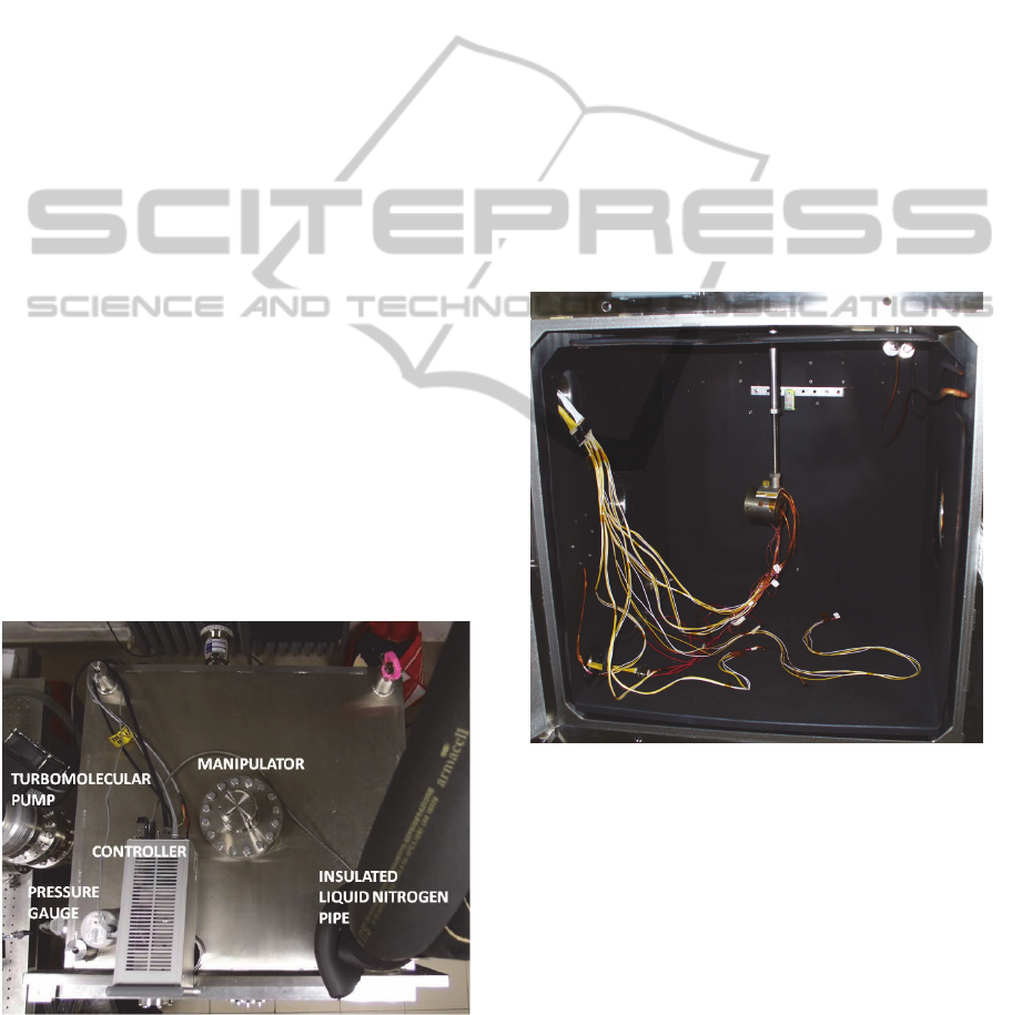
Figure 1: Top view of the vacuum chamber.
The thermo-vacuum facility is mainly composed by
a cubic chamber of 0.6 m side (Figure 1). A first
pump (scroll pump) brings the pressure typically in
the range 10
-2
– 10
-1
millibar. The second pump
(turbomolecular pump) can operate at low pressure
and brings the pressure to the final value in the range
10
-9
-10
-6
millibar. The pressure is monitored with a
wide range gauge, that is constituted by a
combination of a Pirani sensor to monitor pressure
between 10
3
and 10
-4
millibar, and an inverted
magnetron sensor for the range 10
-4
to 10
-9
millibar.
A controller on top of the chamber connected to the
pressure gauge and to the turbomolecular pump,
transfers pressure data to the computer, allowing to
remotely operating the turbomolecular pump. A sun
simulator with an extra-atmospheric (AM0)
spectrum is fed into the chamber through an optical
window with low solar spectrum absorption.
Opposite there is another optical window with a very
accurate surface finish (lambda/20 peak to valley at
632.8 nm) used for testing, with an outside optical
circuit, the optical performances of the specimens
inside the chamber.
Figure 2: Front view of the open vacuum chamber. The
specimen under test, is mounted on the axis of the
manipulator. The cables connect the temperature sensors
and the resistive heaters to the external acquisition system.
The black walls are the liquid nitrogen cooled shrouds.
The sun simulator is outside of the right window.
A single degree of freedom manipulator allows
moving, about a vertical axis, from outside, a
specimen placed inside. An illumination system with
led stripes allows seeing inside through a small
optical window mounted on the front door of the
chamber. A number of electrical feed-throughs with
multipin connectors are used for temperature sensors
(50 pins) and resistive heaters (9 pins); the multipin
CSEDU2015-7thInternationalConferenceonComputerSupportedEducation
468
connectors can withstand a current of 5 A and a
voltage of 500 V. Two independent acquisition
systems are available: the Picotech PT-104 is
specifically used for the platinum resistance
thermometers (PT100 and PT1000) and has four
channels; the HBM MGCPlus, is a 16 slot modular
acquisition system that can be used for any type of
transducers from strain gages to temperature sensors
and accelerometers. At the moment the MGC-Plus
has one slot with eight channels dedicated to PT100
sensors, three slots for a total of 24 channels for the
strain gages and one slot for the accelerometers. A
cryogenic plant completes the facility. It is an open
circuit plant. The liquid nitrogen flows through
several, in series, cryogenic coils, welded in the back
of five copper shrouds which can reach temperatures
as low as -192 °C and cover the five walls of the
chamber (Figure 2). To approach, as closely as
possible, the deep space behaviour, the shrouds are
painted with Aeroglaze Z307 with emissivity ε=
0.89 and absorptivity α= 0.97 in order to be
considered approximately as a black body (Persky,
1999).
3 EXPERIMENTAL TEST
The facility has been designed and built for the
specific purpose of testing the Cube Corner
Reflectors (CCRs) mounted on the surface of the
LARES satellite. The CCRs reflect back to the
ground stations, laser pulses allowing a ranging
estimation with accuracies that can reach few
millimetres, from the best stations. There are about
60 stations all over the world organized in the
International Laser Ranging Service (ILRS)
(Pearlman, 2002). Orbital predictions of the LARES
satellite are provided to the ILRS by the
International Space and Time Analysis Research
Centre (ISTARC) located in Rome at the Sapienza
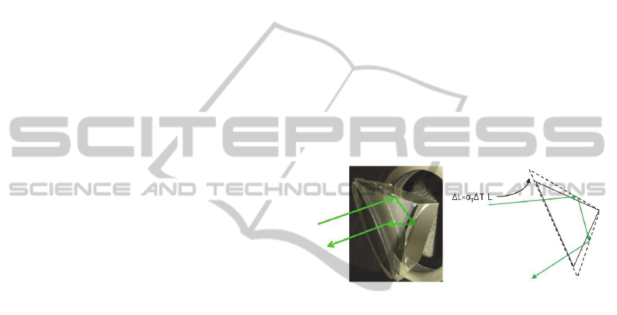
University (Sindoni, 2014). The LARES CCRs rely
on three total internal reflections from the three back
faces (Figure 3 left); regardless of the CCR
orientation the laser beam is reflected back at 180
degrees. Since the satellite moves at a speed of
several km per second, the reflection direction needs
to be changed slightly to compensate for this motion.
That was achieved for LARES by increasing the
dihedral angles of the CCRs by an amount between
1 and 2 arcseconds. As a consequence, the energy
distribution on the ground (called more technically
Far Field Diffraction Pattern or shortly FFDP) re-
distribute, shifting from the centre to an annulus
where the ground station is expected to be, relative
to the satellite. Due to the extreme environmental
conditions in orbit, the temperature gradients on the
CCR could introduce an additional dihedral angle
offset that could prevent the reflected laser beam to
hit the ground station (Figure 3 right). Given a
temperature difference ΔT between the front face
and the apex, the change in the dihedral angle
induced by the ΔT is proportional to α
T
ΔT·L, where
L is the front face diameter and α
T
= 5.1x10
-7
K
-1
is
the coefficient of linear thermal expansion of the
Suprasil (the special glass used to manufacture the
CCRs). Therefore the first tests, performed on the
CCRs were aimed to the determination of the
experimental value of ΔT (Paolozzi, 2012b). Since
those values were exceeding the conservative
threshold fixed by the aforementioned
considerations, a much more complex test was
required for verifying directly the FFDP of the CCR
under the best possible simulated operational
conditions (Paolozzi, 2012c).
Figure 3: LARES CCR. Reflections on the three back
faces send the laser beam back to the station (left).
Thermal gradients cause a malfunctioning of the CCR
(right).
4 IMPLEMENTATION
FOR e-LEARNING
Remote labs for teaching and e-learning have
already been proposed by several projects (Herrera
2006) (Sancristobal, 2011), including also remote
operations for controlling test machines and
manufacturing processes in engineering courses
(Casini, 2001) (Aliane, 2007)(May, 2013); however
in the literature we did not find anything available
about experiments in simulated space environment.
Besides testing and research activity, the lab is
used also for teaching to the students of the courses
in Aerospace and Astronautical Engineering. The
didactic activities involve testing small spacecraft
components, such as university microsatellites. Also
more research oriented activities, such as
experiments to understand the heat transfer and the
behaviour of materials in simulated space
LARES-lab:AThermo-vacuumFacilityforResearchandE-learning-TestsofLARESSatelliteComponentsandSmall
Payloadsfore-Learning
469

environments, are performed. Currently the facility
is not fully automated and the operations over the
internet are limited. Some experiment and tests can
span over several hours or even days, so it is not
very profitable for the students to stay long in the lab
after the scheduled lessons. Thus, in order to
improve the teaching capability, an upgrade of the
facility for remote control aimed at e-learning is
under development. Presently, the data acquisition
systems, the pressure meter and the pump status are
operated via USB cable by a laptop computer (the
server) where remote access software (a Virtual
Network Computing system, VNC) is installed.
With the VNC on the client it is possible to visualize
the server desktop (Figure 4) and make the
acquisition both of the temperatures and pressures as
well as switching on and off the turbomolecular
pump. Figure 4 shows the remotely controlled
desktop with the temperature sensors reading and
pump controller. This configuration is limited since
the current software allows only one client at a time
to connect to the server. Since the system was
devised to be operated by the personnel in charge of
the lab, it gives too much freedom to the client user
on manipulating or deleting files and closing
programs on the host PC. The planned improvement
aims to allow a large number of students to connect
to the lab and to perform operations such as
temperature and pressure control, orientation of the
object under test and data recording. To reach such
an objective the full automation of the operations of
the thermo-vacuum facility is under consideration;
this will allow operating the facility remotely, so that
both students and also researchers could perform
tests directly from anywhere using internet
connection. It is under consideration the possibility
to use software assigning different reading and
writing privileges to different users. Furthermore
there will be also the possibility of sharing many
read only accesses. For instance, while a teacher
operates, many students can observe directly on their
desktop the measurements in progress. At the
moment, we are verifying the possibility to apply
this approach using one of the many desktop sharing
applications available (such as TeamViewer). It
would be desirable that the user with primary write
access privilege can authorize other users to
temporary write privileges: this could be very useful
to let students operate on the system under the
remote supervision of the tutor while other people in
read only mode can observe the performance of the
experiment.
What mentioned so far is relatively convenient
because of low installation cost and manpower. On
the other side, the automation of: manipulator,
cryogenic remotely controlled valve, power control
of resistive heaters, scroll pump and Sun simulator
switching on/off is more demanding.
While the parts connected via USB can be
controlled by a single computer, once provided that
enough USB ports are available (left side of Figure
5), other components (power supply to heaters,
liquid nitrogen valve, switching on and off sun
simulator and scroll pump) need dedicated external
controllers, operated by the computer (right side of
Figure 5).
4.1 Manipulator
A stepper motor coupled with the manipulator
through a drive belt will be controlled by the
computer. The stepper motor will be mounted with
the rotation axis parallel to the manipulator axis. The
motor can be either mounted co-axial to the
manipulator drive, to reduce lateral footprint, or side
mounted and connected to the drive by a pulley. The
design of the coupling between the manipulator and
the motor shall reduce the vibration transmission to
a minimum, although in case the transmitted
vibration will be still too much, it is possible to
mount the manipulator on a passive vibration
damper similar to the one mounted on the
turbomulecolar pump. The stepper motor will be
controlled by an external controller, connected to the
PC by a USB cable.
4.2 Cryogenic Remotely Controlled
Valve
Since small temperature variations of the shroud do
not have a significant impact on the thermal
behaviour of the specimen, a precise temperature
control of the shroud is not required. The main need
is to avoid waste of liquid nitrogen that is directly
poured outside the lab in the air, being the plant an
open circuit. Two families of remotely controllable
valves are available: electrically actuated and
electropneumatic actuated valves. The electrically
controlled valve needs a high peak power to be
started and a high power to be maintained in the
open position (about 100 W), so a power relay is
needed to connect the valve to the power line.
Electrically controlled valves usually do not offer
the possibility of controlling the flow of the
liquid/gas, but can be either full open or full closed.
The models with the option of flow control are very
expensive. Furthermore the power relay needs to be
very reliable, to avoid damaging the actuator.
CSEDU2015-7thInternationalConferenceonComputerSupportedEducation
470
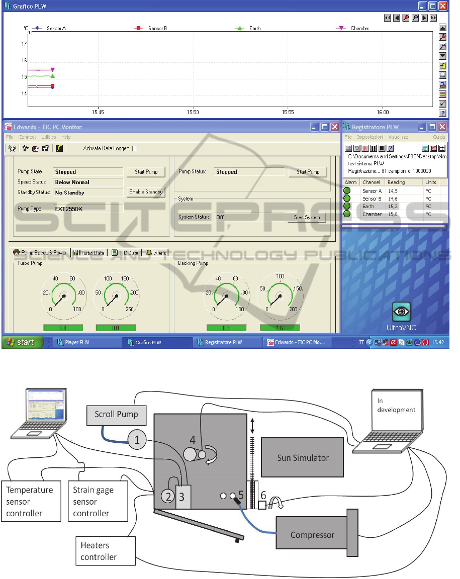
Figure 4: Remote controlled desktop. Temperature sensors behaviour (top), table of temperatures (centre right), monitors
and controls of turbomulecular pump (bottom left), UltraVNC freeware software for remote operations (bottom right).
Figure 5: Full automation of thermo-vacuum facility. Left part is operational, right part is under development. 1-
turbomolecular pump, 2- pressure gauge, 3- turbomulecular pump and pressure gauge controller, 4- manipulator and stepper
motor, 5- cryogenic valve with pneumatic actuation (see Figure 6), 6- stepper motor for sun simulator diaphragm.
LARES-lab:AThermo-vacuumFacilityforResearchandE-learning-TestsofLARESSatelliteComponentsandSmall
Payloadsfore-Learning
471
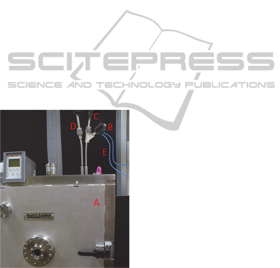
On the other hand, electropneumatic valves are
not only cheaper but are safer and more versatile.
This kind of valves needs to be connected to an air
compressor or to a pressurized air line; the
pressurized air provides the power to operate the
valve and to control the flow of the liquid nitrogen
(Figure 6). Therefore the pneumatic valve is
considered more versatile and convenient for e-
learning. In this case an additional compressor with
relevant remotely controlled switch is required.
Although the temperature of the shroud could be
automatically controlled with temperature feedback
on the valve, for the time being it is preferred to
have, though remotely, manual activation of the
valve.
4.3 Power Control of Resistive Heaters
Also in this case, as in the previous paragraph, a
manual control, though remotely, will be performed.
In fact during the tests, described in a previous
section, it has been realized that specimen
temperature did not vary when the proper voltage
and current are fed to the heater, i.e. no need of
automatic feedback control was required.
Figure 6: Pneumatic actuated valve. The vacuum chamber
(A) is equipped with liquid nitrogen cooled shrouds. The
valve (B) will be fitted to the input nitrogen pipe (C). The
nitrogen leaves the cooling circuit from the output pipe
(D). The valve is operated by controlling the flux of
pressurized air, in the blue pipes (E).
Furthermore from a didactic point of view a too
much automated facility will be less effective. The
heaters are powered by a programmable laboratory
power unit. The power unit can be controlled by a
computer, using its software, to set the voltage and a
limit to the current. The software that programs the
power unit can be operated remotely using the VNC
system or a desktop sharing software mentioned in a
previous section.
4.4 Scroll Pump Switching
The thermo-vacuum facility does not have the
possibility to control the pressure therefore the scroll
pump needs only to be switched on before the test
and off at the end of it. The scroll pump currently
mounted does not allow remote control of the
switch. However, the pump is designed to operate
continuously for days, so a remotely controllable
simple switch on the power cable can be inserted to
serve the purpose.
4.5 Sun Simulator Switching
The sun simulator does not have a standard switch.
A simple but not straightforward procedure needs to
be applied. Also on top of this it has to be
considered that 6kW power is required to operate the
lamp. Two solutions are being considered. The first
one needs a contactor to switch on and off the Sun
simulator. The main disadvantage is the possibility
to damage the Xenon arc lamp if it is switched on
and off too often. The second solution considers a
moving screen to stop the sun simulator beam when
needed. The movement of the screen will be
operated by a servomechanism controlled from the
computer and through the VNC system also
remotely. The disadvantage of this solution is the
power consumption of the lamp that remains on also
when it is not required.
5 CONCLUSIONS
The thermo-vacuum facility created for the LARES
mission is under modification for e-learning
activities. Presently the facility can be operated
remotely only for sensor reading and for switching
on and off the turbomolecular pump. Freeware
software is installed on both the server and the
client. The improvements described in this paper
will allow the full remote access to the facility, for
both research and didactic purposes. In addition to
the present, somewhat limited capabilities, it will be
CSEDU2015-7thInternationalConferenceonComputerSupportedEducation
472

possible to control the mechanical manipulator, the
heaters and the flux of liquid nitrogen Also the sun
simulator beam will be controlled with a diaphragm
and the scroll pump will be turned on and off with a
switch on the power line. In this way both the
students and the researchers will have the possibility
of carrying out experiments of a certain complexity
also remotely.
ACKNOWLEDGEMENTS
The authors wish to thank the Italian Space Agency
for supporting the LARES mission, and in particular
the thermo-vacuum facility, under contracts
I/043/08/0, I/043/08/1, I/034/12/0 and I/034/12/1.
REFERENCES
Aliane, N., 2007. LABNET: A Remote Control
Engineering Laboratory. International Journal of
Online Engineering. Vol. 3, n. 2.
Bosco, A., Cantone, C., Dell'Agnello, S., Delle Monache,
G. O., Franceschi, M. A. Garattini, M., Napolitano, T.,
Ciufolini, I., Agneni, A., Graziani, F., Ialongo, P.,
Lucantoni, A., Paolozzi, A., Peroni, I. Sindoni, G.,
Bellettini, G., Tauraso, R., Pavlis, E. C., Currie, D.G.,
Rubincam, D. P., Arnold, D. A., Matzner, R.,
Slabinski V. J., 2007. Probing gravity in NEO with
high-accuracy laser-ranged test masses. International
Journal of Modern Physics D. Vol. 16, pp. 2271-2285.
Cappelletti, C., Martinotti, G., Graziani, F., 2011.
UniCubeSat: a test for the gravity gradient solar array
boom. In Proceedings of 62nd International
Astronautical Congress, IAC 2011. Cape Town, South
Africa, 3-7 October 2011.
Casini, M., Prattichizzo, D., Vicino, A., 2001. The
Automatic Control Telelab: a remote control
engineering laboratory. In Proceedings of the 40th
IEEE Conference on Decision and Control. Orlando,
04-07 Dec 2001. Vol.4, pp. 3242 – 3247.
Ciufolini, I., 1996. On a new method to measure the
gravitomagnetic field using two orbiting satellites.
Nuovo Cimento A. Vol. 109, n. 12, pp. 1709–1720.
Ciufolini, I., Currie, D.G., Paolozzi, A., 2003. The LARES
mission for testing the dynamics of General Relativity.
In: Proceedings of IEEE Aerospace Conference, Big
Sky, Montana, USA, 5-12 March 2003. Vol. 2, pp.
693-703.
Ciufolini, I. and Pavlis, E. C., 2004. A confirmation of the
general relativistic prediction of the Lense-Thirring
effect. Nature. Vol. 431, pp. 958–960.
Ciufolini, I., 2007. Dragging of inertial frames. Nature.
Vol. 449, pp. 41-47.
Ciufolini, I., Paolozzi, A., Pavlis, E.C., Ries, J., Koenig,
R., Matzner, R., Sindoni, G., and Neumayer, H., 2011.
Testing gravitational physics with satellite laser
ranging. The European Physical Journal Plus. Vol.
126, id 72.
Ciufolini, I., Paolozzi, A., Paris, C., 2012. Overview of the
LARES Mission: orbit, error analysis and
technological aspects. Journal of Physics, Conference
Series. Vol. 354, pp. 1-9.
Ciufolini, I., Paolozzi, A., König, R., Pavlis, E. C., Ries,
J., Matzner, R., Gurzadyan, V., Penrose, R., Sindoni,
G., Paris, C., 2013a. fundamental physics and general
relativity with the LARES and LAGEOS satellites.
Nuclear Physics B - Proceedings Supplements. Vols.
243-244, pp. 180-193.
Ciufolini, I., Moreno Monge, B., Paolozzi, A., Koenig, R.,
Sindoni, G., Michalak, G., Pavlis, E. C., 2013b. Monte
Carlo simulations of the LARES space experiment to
test General Relativity and fundamental physics.
Classical and quantum gravity. Vol. 30, n. 23, pp.1-
11.
Graziani, F., Pulcrano, G., Santoni, F., Perelli, M.,
Battagliere, M. L., 2009. EduSAT: An Italian Space
Agency outreach program. In Proceedings of 60th
International Astronautical Congress 2009, IAC 2009.
Daejeon, South Korea, 12-16 October 2009.
Herrera, O. A., Alves, G. R., Fuller, D., Aldunate R. G.,
2006. Remote lab experiments: opening possibilities
for distance learning in engineering fields. In
Education for the 21st Century- Impact of ICT and
Digital Resources. IFIP International Federation for
Information Processing. Vol. 210, pp. 321-325.
Jaggers, C. H., Meshishnek, M. J., Coggi, J. M., 1993.
Thermal control paints on LDEF: Results of M0003
sub-experiment 18. In NASA. Langley Research
Centre, LDEF: 69 Months in Space. Part 3: Second
Post-Retrieval Symposium, pp. 1075-1092 (SEE N93-
28254 10-99).
Marco, J., Bhojaraj, H., & Hulyal, R., 2003. Evaluation of
thermal control materials degradation in simulated
space environment. In Proceedings of the 9th
International Symposium on Materials in a Space
Environment. 16-20 June 2003, Noordwijk, The
Netherlands. ESA SP-540, Noordwijk, Netherlands:
ESA Publications Division, ISBN 92-9092-850-6,
2003, pp. 359-366.
May, D., Terkowsky, C., Haertel, T., Pleul, C., 2013.
Bringing Remote Labs and Mobile Learning together.
International Journal of Interactive Mobile
Technologies. Vol. 7, n. 3.
NASA, 1995. Analysis of Materials Flown on the Long
Duration Facility: Summary of Results of the
Materials Special Investigation Group. Technical
report. Boeing Defense and Space Group, NASA CR,
May 1995.
Paolozzi, A Ciufolini, I., Vendittozzi, C., F. Passeggio, L.
Caputo, G. Caputo, 2009. Technological challenges
for manufacturing LARES satellite. In Proceedings of
the 60th International Astronautical Congress, IAC
2009. 12-16 October 2009.
Paolozzi, A., Ciufolini, I. and Vendittozzi, C., 2011.
Engineering and scientific aspects of LARES satellite.
LARES-lab:AThermo-vacuumFacilityforResearchandE-learning-TestsofLARESSatelliteComponentsandSmall
Payloadsfore-Learning
473

Acta Astronautica. Vol. 69, pp. 127-134.
Paolozzi, A., Ciufolini, I., Vendittozzi, C., Felli, F., 2012a.
Material and surface properties of LARES satellite. In
Proceedings of the 63rd International Astronautical
Congress, IAC2012. Vol. 8, pp. 6559-6565.
Paolozzi, A., Ciufolini, I., Paris, C., Spano, D., Battaglia,
G., Reinhart, N., 2012b. Thermal tests on LARES
satellite components. In Proceedings of 63rd
International Astronautical Congress, IAC 2012.
Naples, Italy, 1-5 October, 2012.
Paolozzi, A., Ciufolini, I., Paris, C., Sindoni, G., Spano,
D., 2012c. Qualification tests on the optical retro-
reflectors of LARES satellite. In Proceedings of 63rd
International Astronautical Congress, IAC 2012.
Naples, Italy, 1-5 October, 2012c.
Paolozzi, A., Ciufolini, I., 2013. LARES successfully
launched in orbit: satellite and mission description.
Acta Astronautica. Vol. 91, October–November 2013,
pp. 313-321.
Paris, C. and Sindoni, G., 2014. LARES-Lab: a facility for
environmental testing of satellite components and
micro satellites. In: Proceedings of the 2nd IAA
conference on dynamics and control of space systems,
DyCoSS2014. March 24-26, 2014, Roma, Italy. Paper
IAA-AAS-DyCoSS2-14-06-01.
Paris, C., Neubert, R., 2015. Tests of LARES and
CHAMP cube corner reflectors in simulated space
environment. In Proceedings of IEEE Aerospace
Conference 2015. Big Sky, Montana, March 7-14,
2015.
Pearlman, M. R., Degnan, J.J., Bosworth, J.M., 2002. The
international laser ranging service. Adv.Space Res.
Vol. 30, n. 2, 135–143.
Persky, M. J., 1999. Review of black surfaces for space-
borne infrared systems. Review of Scientific
Instruments. Vol. 70, n. 5.
Ries, J. C., Ciufolini, I., Pavlis, E. C., Paolozzi, A.,
Koenig, R., Matzner, R. A., Sindoni, G. And
Neumayer, H., 2011. The Earth’s frame dragging via
Laser Ranged Satellites: a response to ‘Some
considerations on the present-day results for the
detection of frame-dragging after the final outcome of
GP-B’ by L. Iorio. European Physics Letters. Vol. 96,
n. 3, pp. 30002-p1 30002-p5.
Sancristobal, E., Castro, M., Martin, S., Tawkif, M.,
Pesquera, A., Gil, R., Diaz, G., Peire, J., 2011. Remote
labs as learning services in the educational arena. In
Global Engineering Education Conference
(EDUCON), 2011 IEEE. Amman 4-6 April 2011, pp.
1189-1194.
Sindoni, G., Paris, C., Paolozzi, A., Ciufolini, I., Pavlis,
E.C., Gabrielli, A., 2014. Operation and data analysis
of LARES satellite. In Proceedings of 65th
International Astronautical Congress, IAC 2014.
Toronto, Canada, 29 September-3 October 2014.
Testani, P., Teofilatto, P., Nascetti, A., Truglio, M., 2013.
A nadir-pointing magnetic attitude control system for
TigriSat nanosatellite. In Proceedings of 64th
International Astronautical Congress 2013, IAC 2013.
Beijing, China, 23-24 September 2013.
CSEDU2015-7thInternationalConferenceonComputerSupportedEducation
474
