
A Method for Model Checking Feature Interactions
Thomas Pedersen, Thibaut Le Guilly, Anders P. Ravn and Arne Skou
Department of Computer Science, Aalborg University, Selma Lagerl¨ofs Vej 300, 9220 Aalborg East, Denmark
Keywords:
Feature Interaction, Control Systems, Model-driven Development, Home Automation, Model Checking,
Timed Automata.
Abstract:
This paper presents a method to check for feature interactions in a system assembled from independently
developed concurrent processes as found in many reactive systems. The method combines and refines existing
definitions and adds a set of activities. The activities describe how to populate the definitions with models
to ensure that all interactions are captured. The method is illustrated on a home automation example with
model checking as analysis tool. In particular, the modelling formalism is timed automata and the analysis
uses UPPAAL to find interactions.
1 INTRODUCTION
Feature interactions appear when independently well
functioning processes operate concurrently. An ex-
ample from home automation is an automatic win-
dow that sets off an alarm, because of the movement it
causes while opening and closing. To unify processes
like these in a harmonious interplay, engineers can
conduct a behavioural analysis of the system and if
necessary make appropriate modifications. In the ex-
ample, the window could be closed by the alarm sys-
tem. However, this analysis is non-trivial, as building
control systems not only have many features(Metzger
and Webel, 2003), but also have complex interactions
with their environments(Kolberg et al., 2003). There-
fore we investigate tool support for analyzing feature
interactions in systems.
Existing approaches use different models and
tools, for example: dependency graphs (Met-
zger and Webel, 2003), Symbolic Model Veri-
fier (SMV)(Leelaprute et al., 2005), SPIN(Matsuo
et al., 2006), SAT solver(Classen et al., 2008) and
Java Modelling Language (JML)(du Bousquet et al.,
2009). Others handle feature interactions at run-
time(Wilson et al., 2008). All of these approaches
provide an architecture for structuring the mod-
els of the system. Some allow detailing the fea-
tures(Inada et al., 2012; Leelaprute et al., 2005), or
consider the relationship between devices and envi-
ronment(Wilson et al., 2008; Nakamura et al., 2013).
Existing work also provides an overall methodology
for analysis of existing implementations(du Bousquet
et al., 2009), or for eliciting safety properties(Yan
et al., 2007). See Section 6 for more details on re-
lated work.
In this paper, we integrate previous definitions of
home automation systems into one suitable for veri-
fication of systems, when their features are known in
advance. In addition, we propose a set of activities to
identify all relevant elements in the definitions to have
a complete verifiable system. The definitions thus be-
come boxes populated with models using the activi-
ties. The method is tool independent, but we show a
proof-of-concept using timed automata and the UP-
PAAL model checker(Behrmann et al., 2004). This
allows features to be described at a detailed level, for
example with branches, loops, and time. Feature in-
teractions can be detected using verification – a full
state-space exploration of the system. In particular,
our proof-of-concept enhances previous work by us-
ing graphical modelling and including timing aspects.
More concretely we contribute with:
• A definition of control systems and interac-
tions, that combines previous definitions from
software product line engineering(Classen et al.,
2008) with those from an online feature man-
ager(Kolberg et al., 2003). In addition we add
disturbances to complete the system models (Sec-
tion 2).
• A scenario (Section 3) showing a set of activities
to identify necessary models (Section 4).
• A proof-of-concept, where the informal descrip-
tions of the home automation system are tran-
scribed to timed automata and analysed to find
219
Pedersen T., Le Guilly T., Ravn A. and Skou A..
A Method for Model Checking Feature Interactions.
DOI: 10.5220/0005516402190228
In Proceedings of the 10th International Conference on Software Engineering and Applications (ICSOFT-EA-2015), pages 219-228
ISBN: 978-989-758-114-4
Copyright
c
2015 SCITEPRESS (Science and Technology Publications, Lda.)
feature interactions using the UPPAAL tool. This
leads to clarification and disambiguation of the
concepts introduced during modelling (Section 5).
Section 7 concludes with further work and discus-
sion of the benefits and limitations of the method.
2 CONTROL SYSTEMS AND
INTERACTIONS
Our definition of a home automation system, roughly
correspond to the layers used in the online feature
manager(Kolberg et al., 2003), but here we generalise
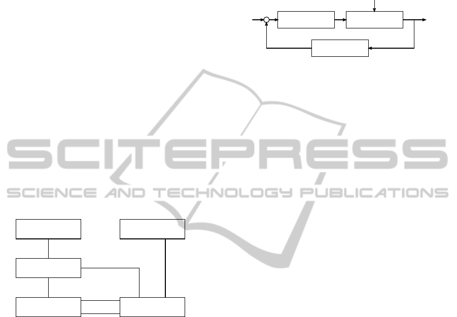
to conventional control concepts. The relationships
between the components is shown in Figure 1. The
home automation system is a control system, that con-
sists of a set of features, F. Each feature, f ∈ F is a
concrete and well defined unit within the control sys-
tem, that controls an aspect of the plant (e.g. home).
An example is a heating feature, f
Heat
, with the pur-
pose of keeping the home comfortable at a comfort-
able temperature, see Figure 2.
Disturbance
Plant Var.
Feature
Control Sys.
Actuator
"has"
"controls"
"PE"
"SE"
"ENV"
1
0..*
0..*
0..*
0..* 0..*
0..* 0..*
0..*
0..*
"reads"
0..*
0..*
Figure 1: Relationship between components in a control
system. The effects of actuators and disturbances are classi-
fied in primary (PE), side (SE), and environmental (ENV).
2.1 The Plant
A plant has a state, a set of devices and a set of dis-
turbances. The state is a set of measurable plant vari-
ables, V. An example of a variable is a room temper-
ature, v
temp
. Sensors measure variables and allow a
feature, f, to read their value. For the scope of this pa-
per we shall exclude delays and noise due to sensors,
and say that sensors are implicitly defined in a vari-
able, v. This means that f will read v directly. The set
of devices D is the combined set of sensors and actu-
ators. As we just excluded sensors it will only consist
of actuators. An actuator is a device, d ∈ D, that is
controllable by features in F and influences values of
variables in V. An example of an actuator is a heater,
d
heater
∈ D, that increases v
temp
. The disturbances, P,
also change values of variables in V, but in contrast
to actuators these are uncontrollable by features in F.
An example of a disturbance is the thermodynamics
of the walls, p
wall
∈ P, that decreases v
temp
(under the
assumption that it is colder outside than inside).
f
Heat
d
heater
v
temp
p
wall
Figure 2: An example of a heating feature, f
Heat
, control-
ling a heater, D
heater
based on the value of a temperature
variable, v
temp
.
2.2 Features and Interactions
To find unwanted feature interactions in the system,
we need to introduce the notion of feature consistency
from requirement engineering. The ith feature, f
i
∈ F,
is a tuple, (R
i
,W
i
, S
i
), where R
i
is the requirements,W
i
is the assumptions about the environment, and S
i
is its
specification(Classen et al., 2008). An example for
f
Heat
:
R
Heat
: The temperature, v
temp
, must be kept between
19
◦
C and 22
◦
C.
W
Heat
: d
heater
warms up the room, but p
wall
cools it
down.
S
Heat
: When v
temp
≤ 19
◦
C then turn on d
heater
.
The feature f
i
is consistent if we take R
i
, S
i
, and W
i
to be predicates, and S
i
,W
i
⊢ R
i
or in plain English: if
the specification, under the given assumptions about
the environment, entails the requirements. To find
feature interactions we combine features and check
whether the combinations are consistent as well. Let
the tuple (R,W, S) be the combination of all n fea-
tures in a system, then the consistency of the full sys-
tem is formally given as: S =
V
n
i=1
S
i
, W =
V
n
i=1
W
i
,
R =
V
n
i=1
R
i
, and S,W ⊢ R.
2.3 Refinement of Features
To use the consistency proof S,W ⊢ R, we need to re-
fine the tuple (R,W, S), using the previous definitions
of a home automation system. Consider a feature, f
i
,
with its specification, S
i
. A difference between re-
quirement engineers and feature managers is that the
former works with specifications and the latter han-
dles actual implementations. We shall let it be up to
the modeller to decide whether to model the specifi-
cation or the implementation.
Let each d ∈ D be a specification of how the de-
vice works and each p ∈ P be a specification of how
ICSOFT-EA2015-10thInternationalConferenceonSoftwareEngineeringandApplications
220

the disturbance effects the variables in V. For exam-
ple: a device d
heater
increases v
temp
, and a disturbance
p
wall
decreases v
temp
. This gives a refinement of the
assumptions into a conjunction of device and distur-
bance specifications. Assuming that the variables in
V are implicitly defined through the sets D and P:
W
i
=
i
k
^
s=1
d
s
∧
i
m
^
s=1
p
s
2.4 Effects
We can have multiple devices in D and multiple dis-
turbances in P manipulating the same variable in V,
used by a number of features in F. Potentially, the
result is many interactions between elements in D, P
and F. It can therefore be advantageous to reduce the
set of interactions, by removing some of the accept-
able ones. A notion for this is primary and side ef-
fects(Wilson et al., 2008). For example, the primary
effect of a refrigerator is to cool the food, but a side
effect is that it warms up the room. The latter is an
interaction with the air conditioner, but one we can
accept (since we prefer both us and our food to stay
cold). We cannot exclude the heat production from
our models, since we still have to ensure that the air
conditioner produces enough cold air to counter the
refrigerator. Figure 1 shows primary (PE) and side ef-
fect (SE) describing the relationships between D and
V, these notations are used in the requirementsR. Fur-
thermore, we add environmental effect (ENV) as a
third type to describe the effects the disturbances in
P have on the variables in V.
2.5 Communication
Home automation systems are deployed using either a
centralised gateway or a distributed architecture. The
centralised gateway is a platform that implements a
common interface to a heterogeneous collection of
devices which communicate using low level proto-
cols, e.g. Homeport(Le Guilly et al., 2013). The ex-
act choice of interface to devices is not a concern for
this paper. We assume that communication is with-
out delays and loss of messages. This is reasonable,
because the network load is typically low for home
automation, and because there are network protocols
that guard against message loss.
3 A HOME AUTOMATION
SCENARIO
Imagine that a home owner hires a company to install
a home automation system with a number of features.
The company prepares the system in an installation
package by combining on-the-shelf products and con-
necting them. Before doing the actual installation,
the company asks the very natural question: Is this
package going to behave as we expect it to? As the
home automation domain consists of many vendors
with different products(Wilson et al., 2008), we are
going to assume it is infeasible to enumerate all vari-
ations of on-the-shelf products. We will also assume
that the company needs to adapt components for each
installation to tailor it to the customer. Thus, it be-
comes infeasible to check all possible configurations
beforehand. Instead, we focus on conducting an of-
fline analysis of the concrete configuration to be in-
stalled. This gives us three advantages:
1. We do not have to consider an exponentially in-
crease of possible configurations,
2. The company can reason about how to solve each
interaction, as they know them before run-time,
3. The company can adapt components to avoid
these interactions and re-verify the system. The
method thus becomes iterative.
3.1 User Requirements
We consider a user requirement to be an informal de-
scription, by the owner of the home, that defines how
the system is supposed to work. Throughout this pa-
per, we let the owner ask for a home automation sys-
tem for a single room, that includes Heating, Ven-
tilation, and Air-conditioning (HVAC), a Humidity
Control Service (HCS), and a Home Security System
(HSS). The set U of user requirements
1
are:
u
HVAC
: The temperature shall be kept between 19
◦
C
and 22
◦
C, by using both a heating and a cooling
device.
u
HCS
: An automatic ventilation system, that will im-
prove humidity.
u
HSS
: An alarm that will sound on intrusion.
1
We use U for the set of informal user requirements, and
reserve the letter R for the more refined and concrete re-
quirements as identified by the company in section 4.
AMethodforModelCheckingFeatureInteractions
221

4 IDENTIFICATION OF
COMPONENTS
In the previous sections, we have seen all specifica-
tions as predicates. However in a design phase it is
more intuitive to use the corresponding models, thus
we shall continue by treating the devices, D, distur-
bances, P, and features, F, to be sets of models and
not predicates
2
. Recall that D and P operate on the
variables in V. We keep each requirement r ∈ R as a
predicate, because they specify properties of the sys-
tem. During this section we will identify the neces-
sary elements of F, V, D, and P to have a complete
verifiable system. We will assume that each element
f ∈ F, d ∈ D, v ∈ V and p ∈ P will have a correspond-
ing model in the modelling tool. The identification is
accomplished by answering a series of questions in a
well defined sequence:
1. Which features are required in the system?
2. For each feature f ∈ F: which input is needed to
make decisions?
3. For each feature f ∈ F: which actuators does the
feature need to perform its task, and which actions
on them?
4. For each device d ∈ D: which effects do each de-
vice have on each variable?
5. For each variable v ∈ V: which disturbances are
there on it?
For the requirements, we start with the set U and
refine each of them into a number of more specific re-
quirements. The extent of a requirement should match
the input of the modelling tool, such that it can answer
each of them. We will not translate them to UPPAAL
syntax before Section 5, thereby leaving the choice
of tool open. When writing the requirements, R, it
is also important to remember the definition of con-
sistency from Section 2.2. Each feature should have
their own set of requirements, and the requirements
for the heating feature f
Heat
should not reference de-
vices used in the HCS feature f
HCS
. This also means
that requirements will be reusable for configurations
where we have no HCS features installed.
4.1 Required Features
By exploring the user requirements, U, we can iden-
tify and plan for four features to be present in the sys-
tem.
2
If we are very formal, we could say that we substitute a
model semantics M (C) for a predicate C; but this seems
an overkill since the predicates are not formalised in the
examples.
f
Heat
: A HVAC heating feature, which increases the
temperature, by turning on a heater, when it be-
comes too cold.
f
Cool
: A HVAC cooling feature, which decreases the
temperature, by turning on an air conditioner,
when it becomes too hot.
f
HCS
: A HCS feature to add fresh air to the room,
by opening a window. We do not consider what
causes this, just allowing it to do so arbitrarily.
f
HSS
: A HSS feature, sounding an alarm on intrusion,
by use of a movement sensor.
We list each feature f ∈ F in the first column in
Table 1.
4.2 Needed Input
The inputs needed by the features to make decisions
are listed in Table 1. The types and purpose of vari-
ables in V are also relevant when modelling the fea-
tures. For instance, v
temp
is a continuous variable and
v
move
is a boolean. For our set-points, user require-
ment u
HVAC
defines the acceptable range. In an at-
tempt (which we will later verify) to allow the two
features to co-exist we set slightly overlapping set-
points. f
heat
will start at v
temp
≤ 19
◦
C and heat until
v
temp
≥ 21
◦
C. f
cool
will start at v
temp
≥ 22
◦
C and stop
at v
temp
≤ 20
◦
C.
Table 1: Variables and devices needed by each feature.
Feature Variables Devices Actions
f ∈ F V
f
⊆ V D
f
⊆ D
f
Heat
{v
temp
} {d
heater
} on/off
f
Cool
{v
temp
} {d
aircon
} on/off
f
HCS
{} {d
window
} open/close
f
HSS
{v
move
} {d
alarm
} on
4.3 Needed Actuators
Also the devices and actions are listed in Table 1. The
HVAC devices can both be turned on and off, the win-
dow can be opened and closed, the alarm can only be
turned on. For this example, it is not necessary to
consider what turns off the alarm again.
4.4 Device Effects
The effects are shown in Table 2, were PE is primary
effect and SE is side effect. It is important to con-
sider this connection after identifying the set of vari-
ables. Consider for example d
window
. Here, we could
easily have considered that it improves humidity in
the room. However, it is not relevant as nothing acts
ICSOFT-EA2015-10thInternationalConferenceonSoftwareEngineeringandApplications
222

on humidity. Instead it is important to ask whether
changing the state of the window causes change to
v
move
and v
temp
– which it does.
Table 2: Mapping between devices and variables.
v
temp
v
move
d
heater
PE
d
aircon
PE
d
window
SE SE
d
alarm
4.5 Disturbances
The included disturbances for our example:
v
temp
slowly approaches the outside temperature,
caused by a wall, p
wall
.
v
move
is caused by a burglar, p
burglar
, while breaking
into the house.
4.6 HVAC Requirements
We recall that, the user requirement u
HVAC
on v
temp
was: The temperature shall be kept between 19
◦
C and
22
◦
C, by using both a heating and a cooling device.
For v
temp
, we can only guarantee that nothing is work-
ing against these set points:
r
1
: When v
temp
< 19
◦
C, no device, d ∈ D, can de-
crease it as its primary effect.
r
2
: When v
temp
> 22
◦
C, no device, d ∈ D, can in-
crease it as its primary effect.
For d
heater
and d
aircon
, we know that they are less
efficient if something works against them:
r
3
: When d
heater
is on, no device, d ∈ D, can decrease
v
temp
as its primary effect.
r
4
: When d
aircon
is on, no device, d ∈ D, can increase
v
temp
as its primary effect.
For f
heat
and f
cool
, we have to guarantee that they
get v
temp
back into the comfortable range, if it moves
out. This also ensures that nothing is preventing the
devices from operating forever. The features also
make the assumption that nothing will turn off their
device while they are operating it:
r
5
: When v
temp
< 19
◦
C then eventually v
temp
≥ 19
◦
C.
r
6
: When v
temp
> 22
◦
C then eventually v
temp
≤ 22
◦
C.
r
7
: d
heater
remains on for the duration that f
Heat
is
active.
r
8
: d
aircon
remains on for the duration that f
Cool
is ac-
tive.
4.7 HCS Requirements
For the HCS service, the user requirement u
HCS
was
An automatic ventilation system, that will improve hu-
midity. For d
window
, we know that devices like heaters
and air conditioners are less efficient if it is open:
r
9
: When d
window
is open, no device, d ∈ D, can de-
crease the environment temperature as its primary
effect.
r
10
: When d
window
is open, no device, d ∈ D, can in-
crease the environment temperature as its primary
effect.
For the HCS, we check if the window can even-
tually open and that it always closes again some time
later:
r
11
: d
window
can eventually open.
r
12
: When d
window
is open it can always close again.
4.8 HSS Requirements
The user requirement, u
HSS
, was An alarm that will
sound on intrusion. We need to ensure that the alarm
is on if and only if the burglaris active. This translates
to the following two queries:
r
13
: d
alarm
is never on when p
burglar
is not present.
r
14
: d
alarm
always turns on when p
burglar
is present.
Now that we have investigated and recorded the
sets of specifications S, assumptions W, and require-
ments R, it remains to prove that S,W ⊢ R. For this we
use timed automata to model S and W and a temporal
logic for R.
5 TIMED AUTOMATA AS
MODELLING TOOL
The purpose of this section is to translate the infor-
mal descriptions from Section 4 into the formalism of
a modelling tool. This will show that the identified
models and requirements are sufficient to find feature
interactions. The chosen tool is UPPAAL(Behrmann
et al., 2004). It is a well-known tool(Behrmann et al.,
2011) for modelling, simulation, and verification of
networks of timed automata. It has become popular
for verification of real-time systems, including proto-
cols, controllers, and schedulers.
5.1 Automata and Queries in UPPAAL
We present a subset of the UPPAAL syntax, suffi-
cient for our needs. Refer to (Behrmann et al., 2004;
AMethodforModelCheckingFeatureInteractions
223

Behrmann et al., 2006) for the full syntax and seman-
tics for UPPAAL.
In UPPAAL, a project is a tuple (A,Var,Chan, Q),
where A = A
1
|A
2
|. . . |A
n
is a composition of n par-
allel timed automata, Var is a set of variable names,
Chan is a set of channel names, and Q is a set of UP-
PAAL queries. An automaton A
i
is given by the tu-
ple (L, l
0
,C, E, I), where L is a set of locations, l
0
is
the initial location, C is a set of clocks
3
, E is a set of
edges, and I assigns invariants to locations. As usual
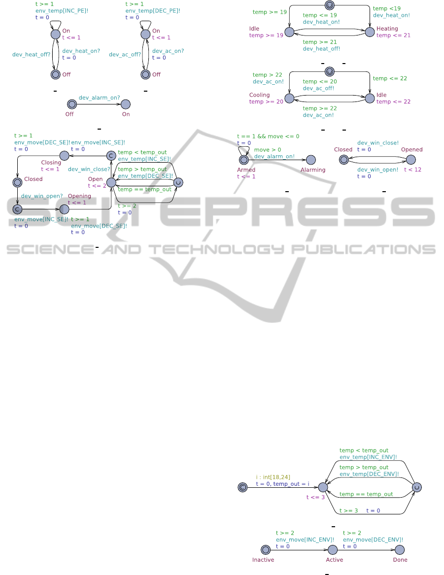
we shall depict automata graphically, see Figure 3-
6. An edge (l, g, a, u, l
′
) ∈ E between two locations, l
and l
′
is annotated with a guard, g, over the sets Var
and C, an action a over the set Chan, and an update,
u, over Var and C.
A UPPAAL query, q ∈ Q is given in a subset
of timed computation tree logic (TCTL). The query
types used in this paper are: A ϕ which means ’ϕ
is true for all reachable states’, E♦ ϕ which means ’ϕ
is true for some reachable state’, and ϕ ψ which
means ’when ϕ is satisfied ψ follows this or some
state later
4
’.
5.2 Variables
We associate each variable v in V to a variable x in
Var in the UPPAAL project. The granularity is impor-
tant to reduce the number of states UPPAAL has to
explore later. In our example, we use integer values
in degrees Celsius for v
temp
. Note that the other mod-
els will restrict the range to [18, 24], thus resulting in
only seven states. An alternative solution can be to
segment it into ranges, e.g. ’low’, ’comfortable’, and
’high’.
To specify what actions are allowed on each vari-
able, v
i
, and to solve a technical problem with detect-
ing why it changed (primary, side or environmental
effect), we add a guardian timed automaton, A
x
∈ A
around x, shown in Figure 3. The available actions,
act
x
[0], ..., act
x
[5] ∈ Chan, represent either direction
of each effect type; primary
PE
, side
SE
, and environ-
ment
ENV
. In UPPAAL, an action is modelled through
a channel, where one automaton is the sender and an-
other is the receiver. The semantics is that both au-
tomata take their transition simultaneously. Our vari-
able automaton will be the receiver; the device and
environment automata will be the senders.
The timed automaton, shown in Figure 3 repre-
sent a generic template where x represent an environ-
ment variable, each act
x
an action that can be per-
formed to update its value and [Min, Max] its do-
main. It is a generic template instantiated with x,
3
In our models, only the identifier
t
will refer to clocks.
4
ϕ ψ is equivalent to A (ϕ =⇒ A♦ ψ)
Figure 3: Generic variable template.
act
x
, and the constants min and max, for each vari-
able. The constants are used to initialise the vari-
able x with a non-deterministic value between min
and max. This ensures that we also cover cases where
the room temperature is too low or too high from the
beginning. To construct queries using effect types,
we pass each action through their own location, e.g.
INC PE
. Thereby we can query for
(temp > 21 &&
VAR Temp.Inc PE)
to check whether a device has in-
creased the temperature as its primary effect, to a
value above 21C. A committed location, shown by
the letter
C
inside the circle, means that time is not
allowed to pass while the automaton is here.
In our example, we have two kinds of variables;
a continuous V
temp
and a boolean V
move
. For both we
use the same template, but interpret x differently. For
the continuous v
temp
, x is simply the temperature of
the room in degree Celsius. For the boolean v
move
,
x > 0 is true and x == 0 is false – e.g. the variable
keeps count of how many objects are moving. Notice
that queries on primary/side/environment effects ap-
ply only to the change of the variable in the boolean
case, which suffices for the example. Alternatively,
one should use three values to account for each effect
type.
5.3 Devices
The general scheme for adding devices is to add the
set of actions, from Table 1, as Act ∈ Chan with the
interface to the device. For example, d
heater
can be
turned on and off and d
window
can be opened and
closed. The automaton A
i
∈ A constructed for each
device d ∈ D will be the receiver on these channels,
and will be the sender on the variable channels created
above.
The HVAC devices, d
heater
and d
aircon
are depicted
in Figure 4(a) and 4(b) respectively. They have two
states, on and off. The heater increase v
temp
by one
ICSOFT-EA2015-10thInternationalConferenceonSoftwareEngineeringandApplications
224
(a)
DEV Heater
. (b)
DEV AirCon
.
(c)
DEV Alarm
.
(d)
DEV Window
.
Figure 4: Devices.
each time unit while it is on. The air conditioner de-
creases it in a similar manner. The clock t keeps track
of the time, and an invariant on the
On
location forces
it to update. The window device, d
window
, in Fig-
ure 4(d) has more states to capture when opening and
closing. When the window is opened, v
temp
moves to-
wards the outside temperature, one degree Celsius ev-
ery second time unit. This means that the temperature
will converge faster (see Figure 6(a) as well) towards
the outside one, when the window is open. Again we
use the time aspect, with the clock t, to capture how
quickly v
temp
changes and how long the window takes
to open and close. The alarm is simple. It cannot be
turned off in this example.
5.4 Features
A feature, f ∈ F is a timed automaton, A
i
∈ A, which
reads the values of global variables in V and performs
actions by synchronising on device channels. The fea-
tures in our example do not add further channels or
global variables. However, if the system later turns
out to have feature interactions, new channels can be
used to allow the features to communicate. Com-
munication and coordination between features can be
used to resolve feature interactions.
The features in our HVAC services are f
Heat
in
Figure 5(a) and f
Cool
in Figure 5(b). Both are similar
and start in an initial state, from which they switch
to
Idle
or
Heating
/
Cooling
, depending on the cur-
(a)
SRV HVAC Heat
.
(b)
SRV HVAC Cool
.
(c)
SRV HSS
. (d)
SRV HCS
.
Figure 5: Feature models.
rent value of v
temp
. From here they attempt to keep
v
temp
between their respective set-points, by switch-
ing on and off their respective devices. The feature
f
HSS
, Figure 5(c), checks v
move
every time unit and
sounds d
alarm
if it is true. Finally, the feature f
HCS
,
in Figure 5(d), opens and closes d
window
. No condi-
tion is set, thus it can do so freely, except that the
window cannot be open for more than 12 time units
at a time. Allowing d
window
to be open forever will
break requirements, because it will prevent d
heater
and
d
aircon
from running forever. This is actually a feature
interaction which was prevented in the design.
5.5 Disturbances
The disturbances, P, are modelled similar to features,
but instead of using devices, they control the variables
in V directly using the environment effect type. Thus
each disturbance p ∈ P is a timed automaton, A
i
∈ A.
(a)
ENV Temp
.
(b)
ENV Burglar
.
Figure 6: Environment.
The wall, p
Wall
in Figure 6(a), starts by choos-
ing a non-deterministic outside temperature, to ensure
AMethodforModelCheckingFeatureInteractions
225

we cover all the cases: lower than the set-points, be-
tween the set-points, and higher than the set-point.
Each three time units the environment moves the
v
temp
closer to this outside temperature. The burglar,
p
Burglar
in Figure 6(b), waits at least two time units
before breaking in (to ensure that all models are set-
tled), and stays inside the house for at least two time
units when active, before leaving again with the loot.
5.6 Checking the Requirements
To perform consistency checks, the models are com-
bined in one network. Both the assumptions, W, and
specifications, S, are timed automata in UPPAAL. We
can therefore use their parallel composition to com-
bine them; A = W
1
|. . . |W
n
|S
1
|. . . |S
n
. Recall that a
W
i
is composed of devices from D and disturbances
from P. In UPPAAL, each requirement is represented
by a UPPAAL TCTL query q that evaluates to true
if the model satisfies it, and to false otherwise. We
can combine queries by logical conjunction;
V
n
i=1
q
i
.
The consistency check for feature f
i
thus becomes
W
i
k S
i
|= R
i
. In practice, for the system to be con-
sistent, we require that all results must list as Passed.
All queries are shown in Table 3 and the complete ex-
haustive check for all queries in the table finishes in
less than 30 seconds on a modern laptop.
In the queries, we checked safety proper-
ties (q
0−4,7−10,13
), liveness properties (q
5,6,12,14
),
and reachability (q
11
). Both states (e.g.
VAR Temp.Dec PE
) and variables (e.g.
temp
)
are used in the queries, but not time. Timing re-
quirements can be incorporated with the UPPAAL
tool, either explicitly using constraints on clocks
in the queries or indirectly by specifying timing
constraints in the models and checking reachability.
Exploring fairness properties is not feasible, but here
one could consider using probabilistic transitions.
Other work has already shown examples on how to
model non-functional requirements see (Repasi et al.,
2012) and analyse reliability(Le Guilly et al., 2015)
in a probabilistic version of UPPAAL.
If queries have syntactical inconsistencies (wrong
variable names, etc.), the UPPAAL tool will protest al-
ready when parsing the query. For queries that evalu-
ate to false, we can use counter-example generated by
Uppaal to understand the cause. Notice that queries
q
9
and q
10
fail, because nothing prevents d
heater
and
d
aircon
from manipulating v
temp
while d
window
is open.
q
13
fails because d
window
moves, thus starting d
alarm
.
All three are therefore examples of feature interac-
tions to be resolved.
6 RELATED WORK
The definitions of features, consistency, and inter-
actions from requirement engineering(Classen et al.,
2008), outlined in Section 2.2, are reused in this pa-
per. We have refined those and presented a novel
approach to perform consistency checks. Their tool
makes use of the event calculus and a SAT solver.
The feature manager(Kolberg et al., 2003; Wilson
et al., 2008) works online. However, we were still
able to utilise the layers and notions of primary/side
effects in our method, see Section 2.3. We note that,
queries q
1−4,9,10
are equivalent to asking if a lock on
the v
temp
has been violated. Similar for queries q
7,8
on d
heater
and d
aircon
.
A third approach to feature interaction analysis
is based on object-oriented descriptions(Nakamura
et al., 2005). Generally they share the same layered
view with features, devices and variables. Compared
to our approach, their early work considered simple
service descriptions without branches, loops, or time.
Branches and loops are later added into the language,
where they apply the SMV model checker(Leelaprute
et al., 2005). This language, and their queries, are
roughly equivalent with ours. The exceptions being
handling of time and that their approach is purely
textual. They have tried using JML (du Bousquet
et al., 2009), concluding that verification was long,
not easy, and only partially successful. They do,
however, provide some interesting perspectives on the
need to abstract from implementation specific details
and on requirements elicitation by reading safety in-
structions. They consider appliance/service pairs in
most of their work, with chains of services first con-
sidered on Event-Condition-Action (ECA) rules (In-
ada et al., 2012). Another important consideration is
the granularity of environmental impacts(Nakamura
et al., 2013), where they ask how much a device
changes a variable.
There is also work on analysing requirements
from an existing development platform, by con-
struction of dependency graphs(Metzger and Webel,
2003). Compared to our work they consider larger
systems on a more abstract level, where they hint at
possible interactions at the requirement level. They
do not model the internal workings of the features.
Another methodology for verification of smart
environments have also been proposed(Corno and
Sanaullah, 2014). Both methods contain roughly the
same steps, but in a different order. They start from an
existing system, thus is able to enumerate all devices
in the system. In our case, we started from the user re-
quirements, thus had to identify the devices by iden-
tifying the features first. They provide more details
ICSOFT-EA2015-10thInternationalConferenceonSoftwareEngineeringandApplications
226
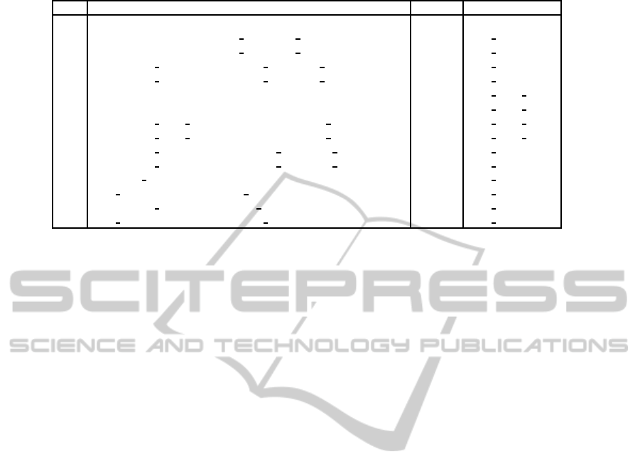
Table 3: Requirements queries in UPPAAL and their results.
UPPAAL Query Result Belongs to
q
0
A[] not deadlock
Passed
q
1
A[] !(temp < 19 && VAR Temp.Dec PE)
Passed
VAR Temp
q
2
A[] !(temp > 22 && VAR Temp.Inc PE)
Passed
VAR Temp
q
3
A[] !(DEV Heater.On && VAR Temp.Dec PE)
Passed
DEV Heater
q
4
A[] !(DEV AirCon.On && VAR Temp.Inc PE)
Passed
DEV AirCon
q
5
temp < 19 --> temp >= 19
Passed
SRV HVAC Heat
q
6
temp > 22 --> temp <= 22
Passed
SRV HVAC Cool
q
7
A[] !(SRV HVAC Heat.Heating && !(DEV Heater.On))
Passed
SRV HVAC Heat
q
8
A[] !(SRV HVAC Cool.Cooling && !(DEV AirCon.On))
Passed
SRV HVAC Cool
q
9
A[] !(DEV Window.Open && VAR Temp.Inc PE)
Failed
DEV Window
q
10
A[] !(DEV Window.Open && VAR Temp.Dec PE)
Failed
DEV Window
q
11
E<> DEV Window.Open
Passed
SRV HCS
q
12
DEV Window.Open --> DEV Window.Closed
Passed
SRV HCS
q
13
A[] !(DEV Alarm.On && ENV Burglar.Inactive)
Failed
SRV HSS
q
14
ENV Burglar.Active --> DEV Alarm.On
Passed
SRV HSS
on the individual steps, which can be used while con-
structing models in our method as well. In contrast
we put more emphasis on the models themselves.
Other work with UPPAAL provide a good exam-
ple of a model for a larger home automation sys-
tem(Augusto and McCullagh, 2007). Their focus
is not on feature interactions and they do not pro-
vide much on requirements. Another example uses
stochastic and hybrid models(David et al., 2015)
in UPPAAL to more precisely model energy aware
buildings with differential equations(David et al.,
2013). There is also an example of how to find non-
functional feature interactions in UPPAAL in the auto-
motive domain(Repasi et al., 2012).
There is also work on software product lines and
safe configurations(Classen et al., 2010). Here they
concentrate on modelling feature compositions and
developing efficient algorithms for model checking
the exponential number of combinations in software
product lines. Another example of similar work is in-
tegration of a component concept in UPPAAL(David
et al., 2010). Both work on a more foundational
level on models, including transition systems and al-
gorithms, and do not directly consider the home au-
tomation domain and features that interacts with their
environments.
7 CONCLUSIONS AND FUTURE
WORK
In this paper we consider systems, where the config-
uration is known at the time of the analysis. In soft-
ware product lines, this method can be used to verify
the individual combinations of features. We refined
the definitions of existing work and suggested a set of
activities to identify elements of the system. We ar-
gue that the activities help to identify which models
are needed to capture all aspects of the problem do-
main, and to identify the relationships between them.
The use of UPPAAL has lead to clarification and dis-
ambiguation of the concepts introduced in the related
work, which is reflected in our definitions.
For the relationship between devices and variables
we used the three effect types; primary, side, and en-
vironmental. As briefly outlined in Section 6, oth-
ers have started to consider a relationship where the
effects are measured in degree of impact. It would
therefore be possible to include this in the models.
While our activities work well for constructing the
models, how to obtain the requirements is still an open
question. An inspiration could be elicitation of safety
properties(Yan et al., 2007). When interactions are
found, there is no automatic way of resolving them.
Either requirements can be relaxed or features can be
further constrained. In both cases it requires insight
into the system.
From several years of experience with model
checking, we have learnt that verification easily suf-
fers state space explosions, as the number of models
and states increase. In our example we had a single
room with three services – in total 12 models. We
showed that on these limited number of components
it is feasible to do the exploration. With more com-
ponents, we would consider a static pruning of the
model, removing features that do not share outputs
and thus cannot interfere. Another option would be
switching to the statistical version of UPPAAL, UP-
PAAL SMC, that performs simulations on the model
instead of full state-space exploration. This could
help to improve scalability, but at the cost of a less ac-
curate answer with a probability for satisfying a prop-
erty (or not). We are currently planning on continuing
this line of work, by studying these options for hand-
ling larger number of components.
AMethodforModelCheckingFeatureInteractions
227

ACKNOWLEDGEMENTS
The underlying research for this paper is partially
supported by the European FP7-ICT project IN-
TrEPID, and the Danish DI ITEK ITOS and TotalFlex
projects
5
.
REFERENCES
Augusto, J. C. and McCullagh, P. (2007). Ambient intelli-
gence: Concepts and applications. Computer Science
and Information Systems, 4(1):1–27.
Behrmann, G., David, A., and Larsen, K. (2004). A tutorial
on UPPAAL. Formal methods for the design of real-
time systems, pages 33–35.
Behrmann, G., David, A., Larsen, K. G., Pettersson, P., and
Yi, W. (2011). Developing uppaal over 15 years. Soft-
ware: Practice and Experience, 41(2):133–142.
Behrmann, G., David, R., and Larsen, K. G. (2006). A tu-
torial on Uppaal 4.0.
Classen, A., Heymans, P., and Schobbens, P.-Y. (2008).
What’s in a feature: A requirements engineering per-
spective. In Fundamental Approaches to Software En-
gineering, pages 16–30. Springer.
Classen, A., Heymans, P., Schobbens, P.-Y., Legay, A.,
and Raskin, J.-F. (2010). Model checking lots of
systems: efficient verification of temporal properties
in software product lines. In Proceedings of the
32nd ACM/IEEE International Conference on Soft-
ware Engineering-Volume 1, pages 335–344. ACM.
Corno, F. and Sanaullah, M. (2014). Modeling and formal
verification of smart environments. Security and Com-
munication Networks, 7(10):1582–1598.
David, A., Du, D., Guldstrand Larsen, K., Legay, A., and
Mikuionis, M. (2013). Optimizing control strategy us-
ing statistical model checking. In Brat, G., Rungta,
N., and Venet, A., editors, NASA Formal Methods,
volume 7871 of Lecture Notes in Computer Science,
pages 352–367. Springer Berlin Heidelberg.
David, A., Larsen, K. G., Legay, A., Mikuˇcionis, M., and
Poulsen, D. B. (2015). Uppaal SMC tutorial. In-
ternational Journal on Software Tools for Technology
Transfer, pages 1–19.
David, A., Larsen, K. G., Legay, A., Nyman, U., and Wa-
sowski, A. (2010). Timed I/O automata: a complete
specification theory for real-time systems. In Proceed-
ings of the 13th ACM international conference on Hy-
brid systems: computation and control, pages 91–100.
ACM.
du Bousquet, L., Nakamura, M., Yan, B., and Igaki, H.
(2009). Using formal methods to increase confidence
in a home network system implementation: a case
study. Innovations in Systems and Software Engineer-
ing, 5(3):181–196.
Inada, T., Igaki, H., Ikegami, K., Matsumoto, S., Naka-
mura, M., and Kusumoto, S. (2012). Detecting service
5
www.fp7-intrepid.eu, itek.di.dk, www.totalflex.dk
chains and feature interactions in sensor-driven home
network services. Sensors, 12(7):8447–8464.
Kolberg, M., Magill, E. H., and Wilson, M. (2003).
Compatibility issues between services supporting net-
worked appliances. Communications Magazine,
IEEE, 41(11):136–147.
Le Guilly, T., Olsen, P., Ravn, A., Rosenkilde, J., and
Skou, A. (2013). Homeport: Middleware for het-
erogeneous home automation networks. In Pervasive
Computing and Communications Workshops (PER-
COM Workshops), 2013 IEEE International Confer-
ence on, pages 627–633.
Le Guilly, T., Olsen, P., Ravn, A. P., and Skou, A. (2015).
Modelling and analysis of component faults and reli-
ability. In Petre, L. and Sekerinski, E., editors, From
Action System to Distributed Systems: The Refinement
Approach. Accepted for publication.
Leelaprute, P., Nakamura, M., Tsuchiya, T., Matsumoto,
K.-i., and Kikuno, T. (2005). Describing and verify-
ing integrated services of home network systems. In
Software Engineering Conference, 2005. APSEC ’05.
12th Asia-Pacific, pages 10 pp.–.
Matsuo, T., Leelaprute, P., Tsuchiya, T., Kikuno, T., Naka-
mura, M., Igaki, H., and Matsumoto, K. (2006). Au-
tomatically verifying integrated services in home net-
work systems. In Proc. International Technical Con-
ference on Circuits/Systems, Computers and Commu-
nications (ITC-CSCC2006), volume 2, pages 173–
176.
Metzger, A. and Webel, C. (2003). Feature interaction de-
tection in building control systems by means of a for-
mal product model. In FIW, pages 105–122.
Nakamura, M., Igaki, H., and Matsumoto, K.-i. (2005).
Feature interactions in integrated services of net-
worked home appliances. In Proc. of Intl. Conf. on
Feature Interactions in Telecommunication Networks
and Distributed Systems (ICFI05), pages 236–251.
Nakamura, M., Ikegami, K., and Matsumoto, S. (2013).
Considering impacts and requirements for better un-
derstanding of environment interactions in home net-
work services. Computer Networks, 57(12):2442–
2453.
Repasi, T., Giessl, S., and Prehofer, C. (2012). Using
model-checking for the detection of non-functional
feature interactions. In Intelligent Engineering Sys-
tems (INES), 2012 IEEE 16th International Confer-
ence on, pages 167–172.
Wilson, M., Kolberg, M., and Magill, E. H. (2008). Con-
sidering side effects in service interactions in home
automation-an online approach. Feature Interactions
in Software and Communication Systems IX, page
172.
Yan, B., Nakamura, M., du Bousquet, L., and Matsumoto,
K.-i. (2007). Characterizing safety of integrated ser-
vices in home network system. In Okadome, T., Ya-
mazaki, T., and Makhtari, M., editors, Pervasive Com-
puting for Quality of Life Enhancement, volume 4541
of Lecture Notes in Computer Science, pages 130–
140. Springer Berlin Heidelberg.
ICSOFT-EA2015-10thInternationalConferenceonSoftwareEngineeringandApplications
228
