
Using Tablets in the Vision-based Control of a Ball and Beam Test-bed
Jared A. Frank, Jos
´
e Antonio De Gracia G
´
omez and Vikram Kapila
Mechanical and Aerospace Engineering, NYU Polytechnic School of Engineering, Brooklyn, NY, 11201, U.S.A.
Keywords:
Ball and Beam, Homography, Immersive, Interface, Networked Control System, Tablet, Vision-Based Control.
Abstract:
Although the onboard cameras of smart devices have been used in the monitoring and teleoperation of physical
systems such as robots, their use in the vision-based feedback control of such systems remains to be fully
explored. In this paper, we discuss an approach to control a ball and beam test-bed using visual feedback from
a smart device with its camera pointed at the test-bed. The computation of a homography between the frames
of a live video and a reference image allows the smart device to accurately estimate the state of the test-bed
while facing the test-bed from any perspective. Augmented reality is incorporated in the development of an
interactive user interface on the smart device that allows users to command the position of the ball on the beam
by tapping their fingers at the desired location on the touchscreen. Experiments using a tablet are performed
to characterize the noise of vision-based measurements and to illustrate the performance of the closed-loop
control system.
1 INTRODUCTION
Several state variables of physical systems, such as
position and orientation, may be measured using
vision-based sensing approaches. Over the last sev-
eral decades, image sensors have been used in the
vision-based control of systems. For example, cam-
eras have been fixed on and off of robots to provide
visual feedback in applications such as path planning
of a single robot (Burschka and Hager, 2001) and for-
mation control of multiple robots (Das, 2002). The in-
corporation of image sensors in both open-loop (i.e.,
a looking phase followed by a separate moving phase)
and closed-loop control has been explored as early as
the 1970’s (Shirai and Inoue, 1973). More recently,
advancements in and miniaturization of camera tech-
nology have allowed the implementation of closed-
loop vision-based control of robot pose, or visual ser-
voing. Specifically, use of continuous visual feedback
in visual servoing enables the real-time control of a
robot’s pose relative to a desired pose (Hutchinson
et al., 1996). Hierarchical architectures have been em-
ployed in which errors from the vision system are rep-
resented in either 3-D world coordinates or 2-D image
coordinates and used as inputs by the joint-level con-
troller (Sanderson and Weiss, 1980).
Vision-based control has been used in applica-
tions besides robotics. Examples include the vision-
based positioning of heliostats in a solar power plant
(Berenguel, 2004), regulation of wastewater flow rate
in sewers (Nguyen, 2009), and impedance force con-
trol in biological cell injections (Huang, 2007). Each
of these vision-based implementations has provided
equal or better accuracy and robustness than the tra-
ditional approaches.
With unprecedented processing speeds, embedded
sensors, and communication support, smartphones
and tablets now represent powerful and portable tech-
nologies. Several innovative mobile applications have
leveraged the cameras in smart devices for vision-
based tasks, e.g., to recognize fingerprints (Li, 2012),
to enable farmers to remotely classify fish species
(Hu, 2012), and to assist visually impaired people in
navigating safely in both indoor and outdoor environ-
ments (Tapu, 2013). Moreover, a system has been de-
veloped that fuses information from several different
smartphone sensors, including both front- and rear-
facing cameras, to monitor driving conditions (You,
2013). Computer vision and machine learning algo-
rithms are performed on the phone to detect the head
pose and eye states of the driver to infer his/her atten-
tiveness and drowsiness during driving, as well as to
detect unsafe conditions such as tailgating, lane weav-
ing, or drifting. It has been noted that similar built-in
features are only found in the most expensive of cars
(You, 2013).
The use of smart devices in the vision-based mon-
itoring and control of physical systems is beginning
92
A. Frank J., Antonio De Gracia Gómez J. and Kapila V..
Using Tablets in the Vision-based Control of a Ball and Beam Test-bed.
DOI: 10.5220/0005544600920102
In Proceedings of the 12th International Conference on Informatics in Control, Automation and Robotics (ICINCO-2015), pages 92-102
ISBN: 978-989-758-123-6
Copyright
c
2015 SCITEPRESS (Science and Technology Publications, Lda.)
to be investigated. Mounted smartphones have been
used for obstacle avoidance of a marine vehicle (El-
Gaaly, 2013) and for the stabilization and control
of unmanned aerial vehicles (Desai, 2013). These
studies use the device camera to capture video and
computer vision techniques such as template match-
ing, feature tracking with random sampling consen-
sus, and color segmentation to enable the autonomous
guidance and navigation of the vehicle. Real-time
vision-based control and teleoperation of formations
of mobile robots has also been accomplished using
smart devices held by an operator. A tablet appli-
cation that uses color segmentation and homography
computation detects camera pose and robot orien-
tation from markers on the robots and environment
(Grieder, 2014). Users holding a tablet pointed at the
robots can interact with augmented reality elements to
issue trajectories that the application uses to compute
and broadcast velocity commands to the robots.
The ball and beam experiment is a classic feed-
back control problem that has been used to illustrate
the control of underactuated systems in the laboratory.
This nonlinear, open-loop unstable system has been
stabilized by using many different approaches includ-
ing proportional-integral-derivative control (Lauko-
nen and Yurkovich, 1993), linear quadratic control
(Pang et al., 2011), fuzzy control (Wang, 1998), slid-
ing mode control (Hirschorn, 2002), and neural net-
works (Wei and Xue, 2010). In prior studies such
as these, the angular orientation and angular rate of
the beam are traditionally measured using sensors at-
tached to the motor shaft such as rotary potentiome-
ter, tachometer, and optical encoder, while the posi-
tion and velocity of the ball are usually measured with
specially built measurement systems such as a linear
slide potentiometer or phototransistors mounted along
the beam (Laukonen and Yurkovich, 1993).
The purchase and installation of such sensors and
complicated measurement systems can burden the
system design in terms of cost, size, wiring, and com-
plexity. In response, vision-based sensing of the ball
and beam system has been explored. However, most
prior efforts have used vision sensors to measure only
one of the state variables. Examples include using
edge detection methods to measure only the beam an-
gle (Petrovic et al., 2002) and using template match-
ing or color segmentation to measure only the ball po-
sition (Dadios, 2000; Hasanzade et al., 2008). These
prior implementations typically use a camera fixed ei-
ther in front of the beam or above the beam and a com-
puter with sufficient memory and processing power to
capture and process the frames from the camera.
In this paper, we investigate the implementation
of state estimation and control techniques alongside
image processing and augmented reality techniques
to render an immersive interface on a mobile device
for direct, mobile, touch-based interaction with a ball
and beam test-bed. Such an approach has not been
explored previously by using smartphone and tablet
platforms with automatic controls experiments, and
may help to reduce some of the wiring, cost, and com-
plexity associated with installing traditional sensing
and control hardware. Moreover, the proposed sys-
tem has the potential to provide students immersive
learning and research experiences that don’t yet ex-
ist in engineering laboratory curricula. First a de-
scription of the system is provided, including the ball
and beam test-bed and the tablet used in the study.
The computer vision algorithm for determining beam
angle and ball position is discussed, including meth-
ods to reduce computational time. Two sampled-data
state-space models are derived to treat the discrete-
time behavior of the system due to image process-
ing and wireless communication of data between the
tablet and a desktop computer driving the test-bed.
These models are used in the design of a Kalman filter
and a linear quadratic regulator (LQR) with integral
feedback to balance the ball on the beam. The design
of the user interface on the mobile application is de-
scribed, which allows users to command the location
of the ball on the beam by tapping their fingers at the
desired location on the tablet screen. Experimental re-
sults are presented and confirm the feasibility of our
proposed system.
2 SYSTEM DESCRIPTION
The ball and beam test-bed used in this study is built
from a DC-motor, a gearbox, a 0.5 meter long lexan
beam, and a smooth 1 inch (0.0254 meter) diam-
eter ball. A desktop computer running the MAT-
LAB/Simulink environment wirelessly receives con-
trol signals from the smart mobile device and uses
them to drive the test-bed using a PC-based data ac-
quisition and control board (DAC) and a power am-
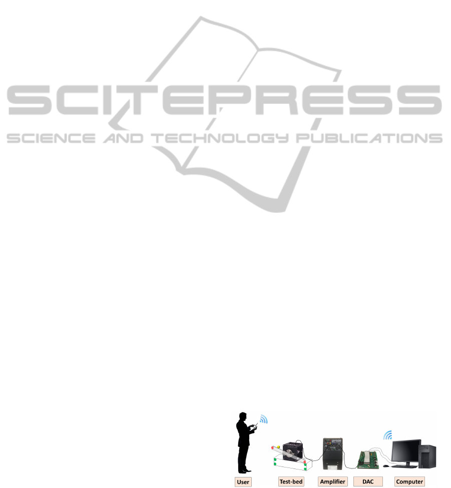
plifier. The system of components used in this study
is shown in Figure 1.
Figure 1: The system used for vision-based control and real-
time interaction with the ball and beam from a smart device.
UsingTabletsintheVision-basedControlofaBallandBeamTest-bed
93

2.1 Smart Device
An Apple iPad 2 is used in this study, which con-
tains a 9.7 inch (250 mm), 1024 × 768 pixel display,
1 GHz dual-core processor, and 0.3-megapixel rear-
facing and 0.7-megapixel front-facing cameras. The
Open-Source Computer Vision Library (OpenCV) is
used in the development of a mobile application to
process the video frames as they are captured by the
smart device’s camera.
3 APPROACH
Vision-based control approaches have the advantage
of performing measurements without contact, and
can therefore aid in applications where contact-based
measurements may be difficult or impossible (Petro-
vic et al., 2002). However, the majority of vision-
based control implementations require a fixed camera
and have not yet been made available on portable de-
vices like smartphones and tablets. In this section,
we present the proposed approach to making vision-
based control accessible for users with smart devices
and providing the user with an immersive augmented
reality interface with which to interact with the ball
and beam test-bed in real-time.
3.1 Computer Vision
Computer vision is a computationally expensive pro-
cessing task. With limited resources on mobile de-
vices, and real-time constraints for stability of the
closed-loop, it is critical that the computer vision al-
gorithm be as efficient as possible for successful ex-
ecution on a mobile platform. Below we present the
methods used to extract measurements of ball position
and beam angle by pointing the mobile device from
an arbitrary perspective and additional techniques to
make processing computationally efficient on the mo-
bile platform.
3.1.1 Marker Detection
Notable problems in vision-based control implemen-
tation include noise in the image, scene disturbances
due to undesired background objects, and non-ideal
lighting conditions (Vincze and Hager, 1999). To
minimize the influence of these effects, the proposed
system is tested with a controlled environment using
color marker segmentation, which has been shown to
be efficient compared to markerless approaches such
as feature detection and haar-based object detection
methods (Masselli et al., 2013). A white backdrop
is placed behind the test-bed, the experiment is fitted
with circular markers of two different colors, and the
ball is painted with a third color. These steps allow
for color segmentation to be performed on the video
frames by setting empirically determined color ranges
within the hue-saturation-value (HSV) color space.
Four green markers are fitted to a stationary plat-
form underneath the test-bed to form the four corners
of a rectangle. Theses markers, once detected, are
used to calculate the homography between the cur-
rent frame in the video and a reference image that is
analyzed once the mobile application is loaded (see
Section 3.1.2). An orange marker is fitted to each end
of the beam and the ball is painted yellow. The mark-
ers are used to calculate the angle of the beam while
the position of the ball is detected directly from the
color segmentation process (see Section 3.1.3).
After the image has been thresholded according
to each of the predefined color ranges, morphological
open and close operations are applied to remove the
presence of noise and to close gaps that may appear
in the interior of the marker regions (Soille, 2003).
The contours that outline each of the detected mark-
ers are determined and used to calculate the image
coordinates of the center and the length in pixels of
the radius of the markers.
Experiments (see Section 5) reveal that 90% of
the computational time is due to the detection of the
colored markers. Therefore, a technique is used in
which the search space for markers is significantly
reduced. For each marker detected in the previous
frame, a square region of interest is created from the
original image that is centered on the previously cal-
culated center point for the marker and has a length
and width that are four times the previously calcu-
lated radius of the marker. This allows the search for
each marker to take place within a small window in
the neighborhood of the marker’s location in the pre-
vious frame. This technique has been shown to ac-
celerate the process of lane detection in vision-based
traffic applications (Kastrinaki et al., 2003). In the
proposed system, the technique significantly reduces
computational time, and allows the frame rate of the
camera to be increased from 20 Hz to 60 Hz.
3.1.2 Homography
The proposed system allows users to interact with the
test-bed while pointing the device camera at the ex-
periment from an arbitrary perspective. To accom-
plish this, two views of the ball and beam system are
considered. The first view, whose coordinate frame
is used as the reference frame, is obtained from a
still image taken with the image plane of the camera
pointed approximately normal to the rotational axis
ICINCO2015-12thInternationalConferenceonInformaticsinControl,AutomationandRobotics
94

of the beam. The other view is obtained from the
frames captured by the camera while the experiment
is running and can change with each frame. To allow
the mobile application to accurately measure the an-
gle of the beam with respect to the horizontal, θ, and
the position of the ball on the beam, x, from an ar-
bitrary perspective, the coordinates of the four green
markers placed on the platform underneath the test-
bed are detected in each of the two views. Since these
four markers lie on a 2-D plane in the 3-D space, a
projective homography matrix, G, can be calculated
between the two views by matching the coordinates
of the corresponding markers in the two views (Hart-
ley and Zisserman, 2003). This matrix establishes
the transformation between the coordinates of a point
p = (u,v,1) in pixels in the current frame and the co-
ordinates of the corresponding point p
∗
= (u
∗
,v
∗
,1)
in the reference frame, up to a scale factor α
g
α
g
p = Gp
∗
.
Therefore, once the center coordinates of the beam
markers and the ball have been calculated in the cur-
rent frame using color segmentation, they can be
transformed back into the reference frame with the
inverse of the homography matrix. It is in this frame
that the beam angle and ball position are calculated.
3.1.3 Position and Angle Measurements
Once the image-based coordinates of the beam mark-
ers and ball position have been transformed into the
reference frame, they can be used to calculate the
beam angle in radians and the normalized ball po-
sition. To calculate the beam angle, the coordinates
of the left beam marker p
∗
l
= (x
∗
l
,y
∗
l
) and right beam
marker p
∗
r
= (x
∗
r
,y
∗
r
) are used in the inverse tangent
function as follows
θ = −tan
−1
y
∗
r
− y
∗
l
x
∗
r
− x
∗
l
.
The negative sign is used to establish the appropriate
sign convention for control. The ball position is cal-
culated as the projection of the vector from the left
beam marker to the ball r
lb
on the vector from the
left beam marker to the right beam marker r
lr
using a
scalar product. To normalize the ball position, the re-
sult of the scalar product is divided by the magnitude
of the r
lr
x
proj
=
r
lb
· r
lr
|r
lr
|
.
This yields a ball position that can be viewed as the
percentage of the beam length traversed by the ball
from the left end to the right end. Through a simple
linear equation using the beam’s length l, the ball po-
sition can be converted to real-world coordinates with
the zero position at the center of the beam
x = (x
proj
− 0.5) × l.
3.1.4 Computing Camera Pose
To project 3D objects onto frames captured by the
camera, one must know the pose of the objects rel-
ative to the camera. Object pose is expressed as a ho-
mogeneous transformation in Euclidean coordinates
and consists of a rotation matrix and a translation vec-
tor. To render augmented reality content in the same
plane as the beam and four green markers, it is conve-
nient to construct a 3D coordinate system in the im-
age with its origin at the center of the top left green
marker. With the locations of the remaining three
markers expressed in this coordinate system, a cali-
brated device camera, and known projected locations
of the four green markers from color segmentation,
the camera pose with respect to the 3D coordinate sys-
tem is estimated by solving a 2D-3D correspondence
problem (Baggio, 2012). This camera pose is inverted
to yield the pose of the 3D coordinate system with re-
spect to the camera frame, and is used to provide a re-
alistic perspective projection when rendering 3D con-
tent in the scene. Figure 2 shows visualizations of the
3D coordinate system rendered by the interface from
three different perspectives explored in this study.
3.2 Interface Design
Mobile applications with access to the embedded
cameras can not only provide sensing and computa-
tion for vision-based control, but can also act as im-
mersive interactive interfaces that provide augmented
reality to enable real-time interaction with the system.
Figure 2 shows screenshots of the mobile application
that was developed on an iPad 2. Buttons used to es-
tablish wireless communication and to begin the con-
trol of the test-bed are provided at the bottom of the
screen.
To provide users with a way to visually assess
the steady-state performance of the system, the Open
Graphics Library for Embedded Systems (OpenGL
ES) is used to render a 3D virtual yellow ball and
project it onto the frames captured by the camera. A
touch gesture recognizer allows the user to single-tap
on the screen at the location where s/he would like
the ball to be stabilized. After the single-tap is de-
tected, the application issues a setpoint to the system
and the interface renders the virtual ball at the nearest
location on the beam to the finger tap. This location
is found by first converting the tapped location from
UsingTabletsintheVision-basedControlofaBallandBeamTest-bed
95
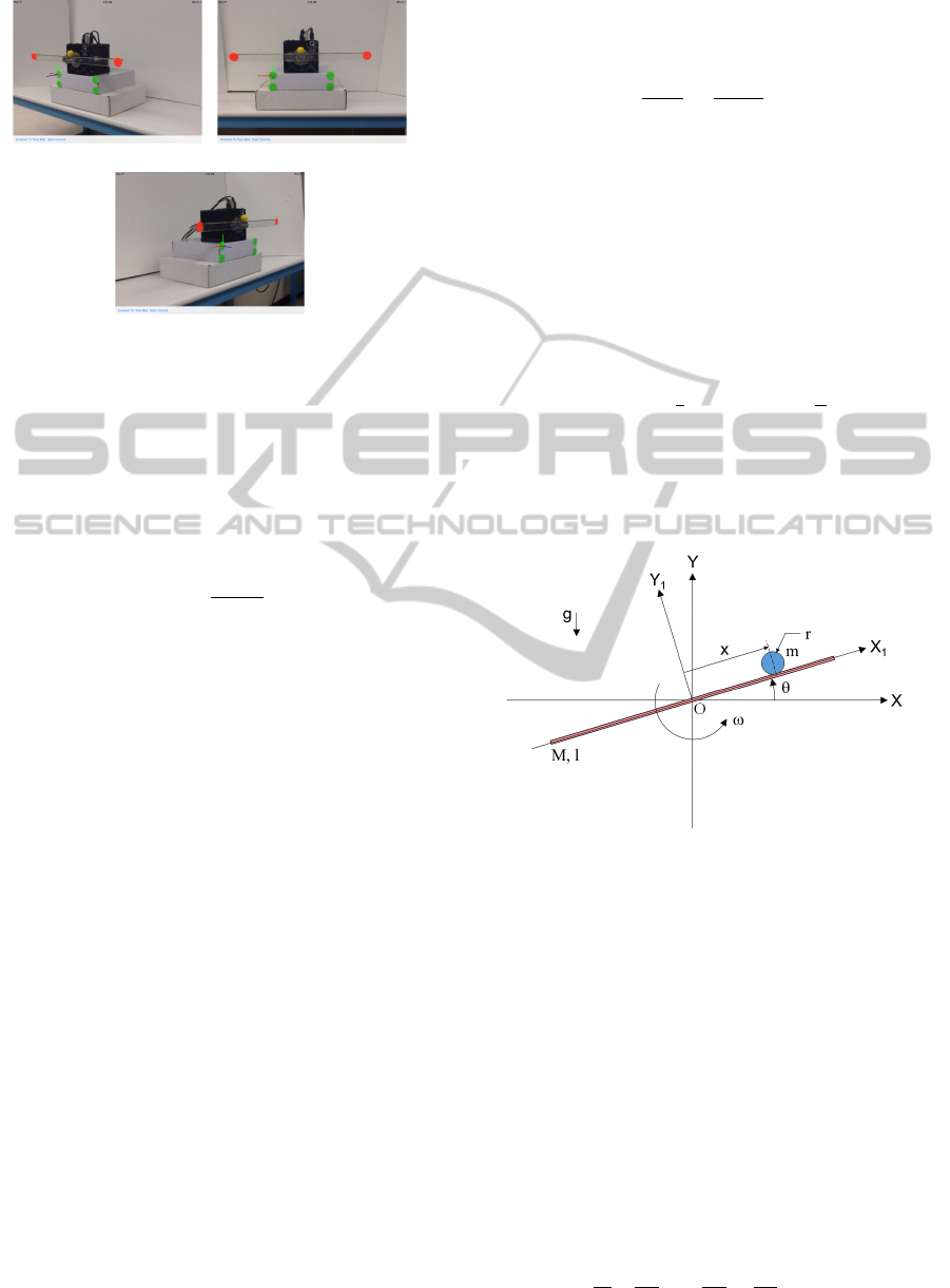
(a) (b)
(c)
Figure 2: Screenshots of the interface while facing the ex-
periment from (a) the right, (b) the front, and (c) the left.
screen pixel coordinates to image pixel coordinates
and then expressing the tapped location with respect
to the reference frame using the inverse of the homog-
raphy matrix. The projection of the tapped location on
the beam is then calculated in the same way as the ball
position measurement
x
proj
=
r
lt
· r
lr
|r
lr
|
,
where r
lt
is the vector from the left beam marker to the
tapped location expressed in the reference frame. This
projected location on the beam is finally expressed
with respect to the the 3D coordinate system found
in Section 3.1.4 and used as the location to render the
virtual sphere.
4 MODELING, ESTIMATION,
AND CONTROL
To design a system that controls the ball position us-
ing visual feedback from a smart device, a cascade
approach is taken to obtain the dynamic model of the
plant (i.e., the dynamics of the beam rotating on the
DC-motor in cascade with the dynamics of the ball
rolling along the beam under the influence of gravity).
This model is discretized and the design of a Kalman
filter and an LQR-based control, with integral action,
are performed.
4.1 Plant Model
4.1.1 Motor-Beam Dynamics
The dynamics of the motor-beam rotation can be ap-
proximated using a simplified model represented by a
first-order transfer function from the voltage input to
the motor U (s) to the angular velocity of the motor-
beam combination Ω(s)
Ω(s)
U(s)
=
K
τs + 1
,
where K is the steady-state DC-gain and τ is the time-
constant. A unit-step voltage input is applied to the
plant to experimentally identify the values of the pa-
rameters K and τ as
K = 1.58V, τ = 0.068s.
A state-space representation for this model is obtained
in which the state x
MB
(t) is composed of the angular
orientation of the beam θ(t) and its angular speed ω(t)
(x
MB
(t) , [θ(t) ω(t)]
T
)
˙x
MB
(t) =
0 1
0 −
1
τ
x
MB
(t) +
0
K
τ
u(t).
4.1.2 Beam-Ball Dynamics
A diagram of the ball and beam system is shown in
Figure 3. Now the dynamics of the ball must be ob-
Figure 3: Diagram of the ball and beam system.
tained. The ball is at a distance x in meters from the
pivot point O, and the beam is rotated by an angle θ
in radians. In this system, the friction between the
surfaces of the ball and beam is assumed to be neg-
ligible. Thus, the equations of motion for this con-
servative system can be derived using Euler-Lagrange
approach. In our case, the motor dynamics have al-
ready been described in the previous subsection, and
we’ve established the relationship between the control
voltage applied to the motor and the angular response
of the beam. Thus, the only generalized coordinate
under investigation is the translational degree of free-
dom, x, which has no generalized force present along
its axis. This gives us the following Euler-Lagrange
equation (Greenwood, 1988)
d
dt
∂T
∂ ˙x
−
∂T
∂x
+
∂P
∂x
= 0,
ICINCO2015-12thInternationalConferenceonInformaticsinControl,AutomationandRobotics
96

where T represents the total kinetic energy of the ball
and P represents the total potential energy of the ball.
The total kinetic energy for the ball arises from the
translation of the ball along the length of the beam,
the rotation of the beam, and the rolling of the ball on
the beam (Bol
´
ıvar and Beauchamp, 2014)
T =
1
2
m
˙x
2
+ x
2
˙
θ
2
+
1
2
J
r
2
˙x
2
,
where J =
2
5
mr
2
is the mass moment of inertia of the
spherical ball about a centroidal axis. The gravita-
tional potential energy of the ball is due to the height
that the beam angle raises or lowers the ball
P = mgx sinθ + mgr cosθ.
Plugging these expressions for the energies into the
Euler-Lagrange equation yields the following nonlin-
ear equation of motion
J
r
2
+ m
¨x − mx
˙
θ
2
+ mgsin θ = 0.
Assuming only small and slow changes in beam an-
gle, the linearized equation of motion for the ball dy-
namics can be written as follows
¨x =
−mg
J/r
2
+ m
θ.
To cascade these dynamics with the motor and beam
dynamics, the simplified equation of motion for the
ball may be expressed in matrix form with the state
x
BB
(t) composed of the ball position x(t) and ball
speed ˙x(t) (x
BB
(t) , [x(t) ˙x(t)]
T
) and the state of the
motor-beam x
MB
as the input
˙x
BB
(t) =
0 1
0 0
x
BB
(t) +
0 0
−mg
J/r
2
+m
0
x
MB
(t).
4.1.3 Simple and Augmented Models
The dynamics of the beam-ball and motor-beam
systems are concatenated, with states x
s
(t) ,
[x
BB
(t) x
MB
(t)]
T
and measurements y
s
1
(t) , x(t) =
x
s
1
(t) and y
s
2
(t) , θ(t) = x
s
3
(t), to form the simple
state-space model for the ball and beam
˙x
s
(t) =
0 1 0 0
0 0
−mg
J/r
2
+m
0
0 0 0 1
0 0 0
−1
τ
x
s
(t) +
0
0
0
K
τ
u(t),
y
s
(t) =
1 0 0 0
0 0 1 0
x
s
(t),
whose state, input, and output matrices can be de-
noted by A
s
, B
s
, and C
s
, respectively. To control the
system so that the ball position y
s
1
(t) = x(t) tracks a
step command r in a way that is robust to effects such
as friction and actuator deadzone, an integrator state
is augmented to the model. By defining the tracking
error as e(t) , y
s
1
(t) −r and letting ξ(t) be defined as
ξ(t) , ˙x
s
(t), we obtain the following dynamics for the
error and ξ(t)
˙e(t) = ˙y
s
1
(t) = C
s
1
˙x
s
(t) = C
s
1
ξ(t),
˙
ξ(t) = ¨x
s
(t) =
d
dt
[A
s
x
s
(t) + B
s
u(t)]
= A
s
˙x
s
(t) + B
s
˙u(t).
If we let u
a
(t) be defined as the derivative of the con-
trol effort, i.e., u
a
(t) = ˙u(t), we can rewrite the aug-
mented dynamics in matrix form as
˙
ξ
˙e
=
A
s
0
C
s
1
0
ξ
e
+
B
s
0
u
a
(t),
y
a
(t) = e(t) =
0 1
ξ
e
.
Therefore, after plugging in the values of A
s
, B
s
, and
C
s
1
(the first row of C
s
) from the complete ball and
beam system, we have the following open-loop aug-
mented state-space model for the system
˙x
a
(t)=
0 1 0 0 0
0 0
−mg
J/r
2
+m
0 0
0 0 0 1 0
0 0 0
−1
τ
0
1 0 0 0 0
x
a
(t)+
0
0
0
K
τ
0
u
a
(t),
y
a
(t) =
0 0 0 0 1
x
a
(t),
where x
a
(t) , [ξ(t) e(t)]
T
is the augmented state
vector and y
a
(t) is the tracking error e(t). For con-
venience, the state, input, and output matrices of this
augmented representation will be denoted as A
a
, B
a
,
and C
a
, respectively. Note that after designing a full-
state feedback controller u
a
(t) = K
a
x
a
(t) for the aug-
mented state equation, one can implement the control
signal u(t) as follows
u(t) = K
a
(:,1 : 4)x
s
(t) + K
a
(:,5)
Z
t
0
[x
s
1
(σ) − r] dσ,
thus avoiding the need to computationally integrate
u
a
(t) to determine u(t). Such an approach is followed
below in the controller design subsection 4.3.
4.1.4 Discretization
For the design of the Kalman filter design and LQR-
controller, the simple and the augmented state-space
models are discretized, respectively, at each sampling
instant kT , k = 0,1,2, .... The simple model yields
the following
x
s
[(k + 1)T ] = φ
s
(T )x
s
[kT ] + θ
s
(T )u[kT ],
y
s
[kT ] = C
s
x
s
[kT ],
UsingTabletsintheVision-basedControlofaBallandBeamTest-bed
97

where φ
s
(T ) , e
A
s
T
is the state transition matrix of
the simple model and θ
s
(T ) ,
R
T
0
φ
s
(T −τ)B
s
dτ. The
augmented model yields
x
a
[(k + 1)T ] = φ
a
(T )x
a
[kT ] + θ
a
(T )u
a
[kT ],
y
a
[kT ] = C
a
x
a
[kT ],
where φ
a
(T ) , e
A
a
T
is the state transition matrix
of the augmented model and θ
a
(T ) ,
R
T
0
φ
a
(T −
τ)B
a
dτ. Before designing the Kalman filter and LQR-
controller for the above sampled-data models with
sampling time T , the observability (simple system)
and controllability (augmented system) are verified
by confirming that the observability matrix M
o
(T ) of
the simple model and controllability matrix M
c
(T ) of
the augmented model are of full rank
M
o
(T ) =
C
s
C
s
φ
s
(T )
.
.
.
C
s
φ
3
s
(T )
,
M
c
(T ) =
φ
a
(T ) φ
a
(T )θ
a
(T ) . .. φ
4
a
(T )θ
a
(T )
.
4.2 State Estimation
The proposed computer vision approach provides
measurements y
s
of only two of the states needed for
full-state feedback control. These measurements will
contain noise, due to factors such as imperfections
in image quality, scene illumination, and the color
segmentation procedure. Noise associated with the
detected centers of the markers will result in noisy
ball position and beam angle measurements. Noise in
the centers of green markers will affect the measure-
ments by varying the calculation of the homography
matrix, while noise in the orange and yellow mark-
ers will vary the computation of the measurements
themselves. Therefore, a steady-state discrete-time
Kalman filter is used to obtain estimates of the state of
the discretized simple model, ˆx
s
, which includes two
unmeasured states (i.e, the speed of the ball along the
beam and the angular speed of the beam) as well as
the two measured states (i.e., ball position and beam
angle). This Kalman filter is implemented at each
time step k by propagating the following equation
ˆx
s
[(k + 1)T ] = φ
s
ˆx
s
[kT ] + θ
s
u[kT ]
+ L(y
s
[kT ] −C
s
ˆx
s
[kT ]),
where L = (φ
s
QC
T
s
)(C
s
QC
T
s
+ V
2
)
−1
is the Kalman
gain, V
2
is the measurement noise covariance matrix,
and Q is obtained by solving the discrete-time alge-
braic Riccati equation (Lewis, 1986)
Q = φ
s
Qφ
T
s
+V
1
−(φ
s
QC
T
s
)(V
2
+C
s
QC
T
s
)
−1
(φ
s
QC
T
s
)
T
,
where V
1
is the process noise covariance matrix. To
give the filter confidence in the time updates com-
ing from the model, the process noise covariance
matrix V
1
= 10
−6
× I
4
is chosen to be a diagonal
matrix with elements that are small in comparison
to the measurement noise covariance matrix V
2
=
diag(0.0024
2
,0.004
2
), which is chosen to be diago-
nal with variances determined from experimental data
(see Section 5.2)
4.3 Controller Design
A linear quadratic regulator is designed such that the
ball position is weighed heavily and the maximum
control effort is within the allowable range of the
motor. The digital full-state feedback control law
u[kT ] = −K
c
ˆx[kT ] is used, where K
c
is the control
gain matrix and ˆx is the state estimate ˆx
s
returned
from the Kalman filter concatenated with the discrete-
time integral of the error in ball position e[kT ] =
ˆx
s
1
[kT ] − r. An LQ approach is applied to the aug-
mented system (φ
a
,θ
a
) to design K
c
so that the fol-
lowing quadratic cost function J(u
a
) is minimized
J(u
a
) =
∞
∑
kT =1
(x
T
a
[kT ]R
1
x
a
[kT ] + u
T
a
[kT ]R
2
u
a
[kT ]),
where R
1
is a nonnegative-definite state weighting
matrix and R
2
is a positive-definite control weight-
ing matrix. The control gain K
c
is obtained from
K
c
= (θ
T
a
Pθ
a
+R
2
)
−1
(θ
T
a
Pφ
a
), where P is the solution
to the discrete-time algebraic Riccati equation (Zhou,
1996)
P = φ
T
a
Pφ
a
+R
1
−(θ
T
a
Pφ
a
)
T
(θ
T
a
Pθ
a
+ R
2
)
−1
(θ
T
a
Pφ
a
).
To give the controller priority over regulating
ball position, the state weighting matrix R
1
=
diag(50,1,2, 1,10) is a diagonal matrix with the two
elements corresponding to proportional and integral
control of ball position larger than the other elements.
The control weighting matrix R
2
= 4 is tuned until
control actions calculated by the controller are within
the allowable voltage range of the motor.
4.4 Implementation
Before implementing the state estimation and control
on a mobile platform, the MATLAB/Simulink envi-
ronment is used on a desktop computer to compute
the values of the matrices associated with the state-
space models, the Kalman filter design, and controller
design. Functions written in the application code use
data structures provided by OpenCV to perform the
necessary 4th- and 5th-order recursive matrix-vector
equations. These functions run sequentially alongside
ICINCO2015-12thInternationalConferenceonInformaticsinControl,AutomationandRobotics
98
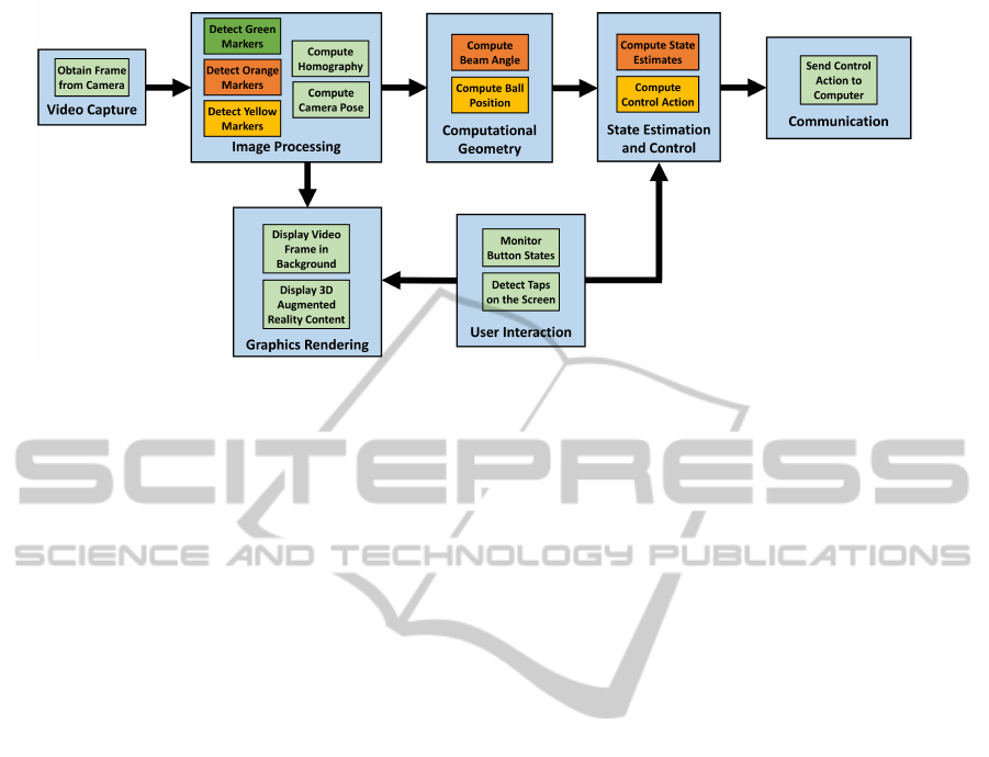
Figure 4: Flowchart outlining the architecture implemented on the tablet application.
those for image processing and user interaction. Fig-
ure 4 illustrates the architecture implemented on the
mobile application.
The noisy measurements of the beam angle and
ball position, as calculated using perspective geome-
try and vector relationships, are input along with the
value of the previously computed control action into
the state estimation function. This function uses the
value of the control action from the previous time step
to compute the prediction update, and then uses the
values of the measurements to compute the correc-
tion of the estimate. This estimate is then fed, along
with the setpoint obtained from the the last tapped lo-
cation on the touchscreen, into a function to update
the control action.
To compute a discrete-time integral of the
tracking error e(t) = x
s
1
(t) − r, namely, I(t) ,
R
t
0
[x
s
1
(σ) − r] dσ, the standard forward Euler method
is used as below
I[kT ] = I[(k − 1)T ] + Te[(k − 1)T ].
Before computing control actions, the estimates ac-
quired for the derivatives of the beam angle and ball
position are fed through a discrete-time low-pass fil-
ter, which is implemented as the following exponen-
tially weighted moving average filter
ˇx
s
i
[kT ] = α ˇx
s
i
[(k − 1)T ] + (1 − α) ˆx
s
i
[kT ], i = 2, 4,
where ˇx
s
i
[·] is the filtered version of derivative signal
ˆx
s
i
. This discrete-time low-pass filter is obtained by
discretizing a continuous-time low-pass filter 1/(1 +
ˆ
τs) yielding the filter parameter α =
ˆ
τ/(
ˆ
τ + T ) where
ˆ
τ = 1/15.
5 EXPERIMENTAL RESULTS
5.1 Computation and Communication
Choosing a sampling rate is a critical part of the de-
sign of the proposed system, since this rate has a sig-
nificant impact on the closed-loop stability of the sys-
tem. Although communication at rates between 10-20
Hz are usually suitable for most teleoperation tasks,
this range is hardly enough in feedback control appli-
cations. Since the architecture of the mobile applica-
tion is designed such that graphics rendering is per-
formed on a separate thread than video capture and
image processing, the sampling rate is limited by the
frame rate of the camera, which is limited by the com-
putation time of the image processing routine. After
performing an experiment involving the collection of
350 samples, the mean computation time was found
to be 13.28 milliseconds with a standard deviation of
0.283 milliseconds, which is fast enough to support a
60 Hz frame rate from the camera. Therefore, vision-
based ball position and beam angle measurements are
obtained and rendered on the tablet interface at a rate
of 60 Hz, or in intervals of 16.67 milliseconds. The
control signal is also communicated to the test-bed at
the rate of 60 Hz. This is a suitable interval for feed-
back control of this system, since prior studies have
noted that the dynamics of the ball and beam system
require sampling intervals less than 60 milliseconds
(Petrovic et al., 2002).
5.2 Noise Analysis
To investigate the noise characteristics of vision-
based measurements, raw data is obtained from the
iPad as it is held by a user and while the ball and beam
UsingTabletsintheVision-basedControlofaBallandBeamTest-bed
99
(a) (b)
(c) (d)
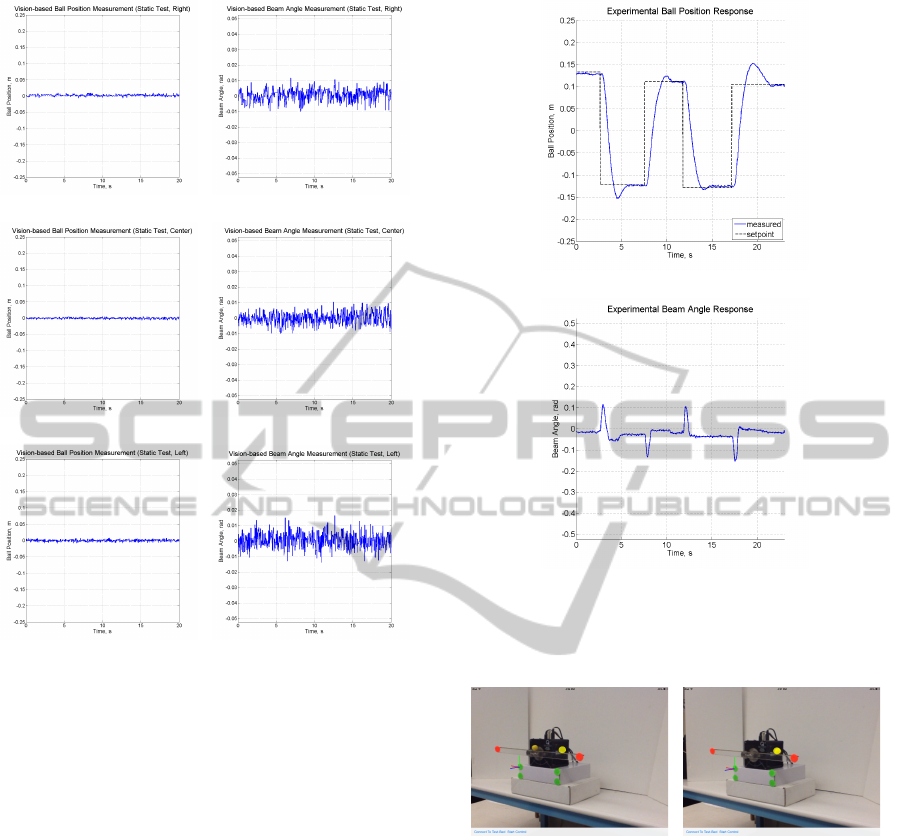
(e) (f)
Figure 5: Ball position and beam angle measurements from
a perspective (a),(b) to the right, (c),(d) in front, and (e),(f)
to the left of the test-bed while performing a static test.
test-bed is in its zero configuration and not being con-
trolled. This sensor data was collected and plotted
from three different perspectives: from the right of
the test-bed, directly in front of the test-bed, and to
the left of the test-bed (see Figure 5). Over the course
of 20 second runs, the means of the three sets of ball
positions are 0.0021,−7.4461×10
−4
, and 0.0050 me-
ters, and the standard deviations are 0.0025, 0.0021,
and 0.0027 meters, respectively. The means of the
three sets of beam angles are −0.0146, 0.0045, and
1.3782 × 10
−4
radians, and the standard deviations
are 0.0037, 0.0036, and 0.0046, respectively. The re-
sults of several paired t-tests conclude that no two sets
of data are statistically from different means. In other
words, the proposed system adequately uses perspec-
tive transformations to approximate the state of the
system from arbitrary perspectives of the observer.
5.3 Ball and Beam Control
To explore the feasibility of using the tablet to per-
form vision-based control of the test-bed, experiments
(a)
(b)
Figure 6: Experimental results for the (a) ball position and
(b) beam angle when using vision-based control of the test-
bed with the camera of an iPad 2.
(a) (b)
Figure 7: Screenshots of the mobile application (a) before
and (b) after the test-bed is commanded to track the setpoint.
are performed while holding the tablet such that it
points at the test-bed from the right side. The response
of the system is recorded while several non-zero step
commands are issued by tapping on the device screen
at locations approximately 25% and 75% of the beam
length. Figure 6(a) shows the ball position response
plotted alongside the setpoint issued by the user and
Figure 6(b) shows the beam angle response. The ball
and beam system exhibits mild oscillations in its re-
sponse to commands, and on average settles at the de-
sired state in 3 to 4 seconds. With more robust com-
puter vision techniques and mobile devices that can
support superior image quality and faster frame rates,
we are confident that time-domain performance can
ICINCO2015-12thInternationalConferenceonInformaticsinControl,AutomationandRobotics
100

be improved further. Screenshots of the application
(see Figure 7) show the perspective of the tablet as
well as the appearance of the interface before and af-
ter the button is pressed to start the control of the ball.
6 CONCLUSIONS
This paper presented the development of a vision-
based approach to control a ball and beam test-bed
using the camera onboard a tablet to provide mea-
surements as the tablet is pointed at the test-bed from
an arbitrary perspective. A touch-based user inter-
face with augmented reality allows users to interact
with the test-bed in real-time as the system is being
controlled. Results from experiments validate the use
of tablets as portable, hand-held, vision-based sensor,
estimation, and control components in a wireless net-
worked control system for plants whose states can be
estimated from vision-based measurements.
ACKNOWLEDGEMENTS
This work is supported in part by the National Science
Foundation awards RET Site EEC-1132482, GK-12
Fellows DGE: 0741714, and DRK-12 DRL: 1417769,
and NY Space Grant award 48240-7887. The authors
thank Anthony Brill and Sai Prasanth Krishnamurthy
for their support.
REFERENCES
Baggio, D. (2012). Mastering OpenCV with Practical Com-
puter Vision Projects. Packt Publishing Ltd.
Berenguel, M., et al. (2004). An artificial vision-based con-
trol system for automatic heliostat positioning offset
correction in a central receiver solar power plant. So-
lar Energy, 76(5):563–575.
Bol
´
ıvar, C. and Beauchamp, G. (2014). Modelling the
ball-and-beam system from newtonian mechanics and
from lagrange methods. In Proc. Latin American and
Carribbean Conference on Engineering and Technol-
ogy, page 176.
Burschka, D. and Hager, G. (2001). Vision-based control
of mobile robots. In IEEE Int. Conf. Robotics and
Automation, volume 2, pages 1707–1713.
Dadios, E.P., et al. (2000). Vision guided ball-beam balanc-
ing system using fuzzy logic. In IEEE Conf. Industrial
Electronics Society, volume 3, pages 1973–1978.
Das, A.K., et al. (2002). A vision-based formation control
framework. IEEE Trans. Robotics and Automation,
18(5):813–825.
Desai, A., et al. (2013). Stabilization and control of
quad-rotor helicopter using a smartphone device.
IS&T/SPIE Electronic Imaging, 8662(8):1–9.
El-Gaaly, T., et al. (2013). Visual obstacle avoidance for
autonomous watercraft using smartphones. In Au-
tonomous Robots and Multirobot Systems Workshop.
Greenwood, D. (1988). Principles of Dynamics. Prentice-
Hall Englewood Cliffs, NJ.
Grieder, R., et al. (2014). Multi-robot control and interac-
tion with a hand-held tablet. In Proc. IEEE Int. Conf.
Robotics and Automation, volume 131.
Hartley, R. and Zisserman, A. (2003). Multiple View Geom-
etry in Computer Vision. Cambridge University Press.
Hasanzade, I., Anvar, S., and Motlagh, N. (2008). Design
and implementation of visual servoing control for ball
and beam system. In Int. Symp. Mechatronics and Its
Applications, pages 1–5.
Hirschorn, R. (2002). Incremental sliding mode control of
the ball and beam. IEEE Trans. Automatic Control,
47(10):1696–1700.
Hu, J., et al. (2012). Fish species classification by color,
texture and multi-class support vector machine using
computer vision. Computers and Electronics in Agri-
culture, 88:133–140.
Huang, H., et al. (2007). Visual-based impedance force
control of three-dimensional cell injection system.
In IEEE Int. Conf. Robotics and Automation, pages
4196–4201.
Hutchinson, S., Hager, G., and Corke, P. (1996). A tutorial
on visual servo control. IEEE Trans. Robotics and
Automation, 12(5):651–670.
Kastrinaki, V., Zervakis, M., and Kalaitzakis, K. (2003). A
survey of video processing techniques for traffic appli-
cations. Image and Vision Computing, 21(4):359–381.
Laukonen, E. and Yurkovich, S. (1993). A ball and beam
testbed for fuzzy identification and control design. In
American Control Conference, pages 665–669. IEEE.
Lewis, F. (1986). Optimal Estimation: With an Introduction
to Stochastic Control Theory. Wiley New York et al.
Li, G., et al. (2012). Testing mobile phone camera based fin-
gerprint recognition under real-life scenarios. Norsk
informasjonssikkerhetskonferanse, 2012.
Masselli, A., Hanten, R., and Zell, A. (2013). Robust real-
time detection of multiple balls on a mobile robot. In
European Conf. Mobile Robots, pages 355–360.
Nguyen, L., et al. (2009). Vision-based system for the con-
trol and measurement of wastewater flow rate in sewer
systems. Water Science and Technology, 60(ECOL-
ARTICLE-2009-029):2281–2289.
Pang, Z.-H., Zheng, G., and Luo, C.-X. (2011). Augmented
state estimation and LQR control for a ball and beam
system. In Int. Conf. Industrial Electronics and Appli-
cations, pages 1328–1332.
Petrovic, I., Brezak, M., and Cupec, R. (2002). Machine vi-
sion based control of the ball and beam. In Int. Work-
shop Advanced Motion Control, pages 573–577.
Sanderson, A. and Weiss, L. (1980). Image-based vi-
sual servo control using relational graph error signals.
Proc. IEEE, 1074.
UsingTabletsintheVision-basedControlofaBallandBeamTest-bed
101

Shirai, Y. and Inoue, H. (1973). Guiding a robot by visual
feedback in assembling tasks. Pattern Recognition,
5(2):99–108.
Soille, P. (2003). Morphological Image Analysis: Prin-
ciples and Applications. Springer-Verlag New York,
Inc.
Tapu, R., et al. (2013). A smartphone-based obstacle de-
tection and classification system for assisting visually
impaired people. In Int. Conf. Computer Vision Work-
shops, pages 444–451.
Vincze, M. and Hager, G. (1999). Robust Vision for Vision-
Based Control of Motion. Wiley-IEEE Press.
Wang, L.-X. (1998). Stable and optimal fuzzy control of
linear systems. IEEE Trans. Fuzzy Systems, 6(1):137–
143.
Wei, W. and Xue, P. (2010). A research on control meth-
ods of ball and beam system based on adaptive neural
network. In Int. Conf. Computational and Information
Sciences, pages 1072–1075.
You, C.-W., et al. (2013). Carsafe app: Alerting drowsy and
distracted drivers using dual cameras on smartphones.
In Proc. Int. Conf. Mobile Systems, Applications, and
Services, pages 13–26.
Zhou, K., et al. (1996). Robust and Optimal Control. Pren-
tice Hall New Jersey.
ICINCO2015-12thInternationalConferenceonInformaticsinControl,AutomationandRobotics
102
