
Logical Unified Modeling for NoSQL Databases
Fatma Abdelhedi
1,2
, Amal Ait Brahim
1
, Faten Atigui
3
and Gilles Zurfluh
1
1
Toulouse Institute of Computer Science Research (IRIT), Toulouse Capitole University, Toulouse, France
2
CBI
2
– TRIMANE, Paris, France
3
CEDRIC-CNAM, Paris, France
Keywords: Big Data, NoSQL, UML Conceptual Model, MDA, QVT.
Abstract: NoSQL data stores are becoming widely used to handle Big Data; these systems operate on schema-less
data model enabling users to incorporate new data into their applications without using a predefined
schema. But, there is still a need for a conceptual model to define how data will be structured in the
database. In this paper, we show how to store Big Data described by conceptual model within NoSQL
systems. For this, we use the Model Driven Architecture (MDA) that provides a framework for models
automatic transformation. Starting from a conceptual model describing a set of complex objects, we propose
transformation rules formalized with QVT to generate NoSQL physical models. To ensure efficient
automatic transformation and to limit the impacts related to technical aspects of NoSQL systems, we
propose a generic logical model that is compatible with the three types of NoSQL systems (column,
document and graph). We provide experiments of our approach using a case study related to the health care
field. The results of our experiments show that the proposed logical model can be effectively transformed
into different NoSQL physical models independently of their specific details.
1 INTRODUCTION
Company digital transformation is accompanied by
an exponential growth in data collected which is
known as Big Data. Generally, we describe Big Data
according to three vectors (Gartner, 2001): Volume
(many terabytes of data that need to be processed),
Variety (different data type including factors such as
format, structure, and sources) and Velocity (speed
of data loading and processing). Relational systems
representing the majority of DBMS, prove to be
inadequate for all applications, especially these
involving Big Data (Abello, 2015). As a result, new
kind of DBMS, known as “NoSQL” (Cattell, 2011),
has appeared. These systems, with flexible schemas,
are well suited for managing large volume of data.
They also offer good performance when scaling up
(Angadi, 2013). NoSQL encompasses a wide variety
of different systems that were developed to meet
specific needs. They can be classified into four basic
types: key-value, column-oriented, document and
graph-oriented. In this paper, we exclude the key-
value because column-oriented, document-oriented
and graph-oriented systems extend the concepts of
key-value systems (Abadi, 2008).
Big Data applications developers are faced with
the problem of storing data in NoSQL systems. To
address this problem, some solutions dealing with
model transformation have been proposed. Li et al.
(Li, 2014) propose MDA-based process to transform
UML class diagram into column-oriented physical
HBase model. Daniel et al. (Daniel, 2016) describe
mapping between an UML conceptual model and a
NoSQL physical model compatible only with graph-
oriented systems. In these works, the adopted
processes depend only on one type of NoSQL
systems (column-oriented in (Li, 2014) and graph-
oriented in (Daniel, 2016)). However, users need to
choose the system type most suited to their needs.
For example, processing operations require access to
hierarchically structured data, document-oriented is
the most adapted solution.
The main purpose of our work is to assist
developers in implementing Big Data on NoSQL
systems. For this, we propose a new MDA-based
process that transforms a conceptual data model
describing Big Data into several NoSQL physical
models. This automatic process allows developer to
choose the system type he wants to use.
The rest of the paper is structured as follows:
Abdelhedi, F., Brahim, A., Atigui, F. and Zurfluh, G.
Logical Unified Modeling for NoSQL Databases.
DOI: 10.5220/0006311702490256
In Proceedings of the 19th International Conference on Enterprise Information Systems (ICEIS 2017) - Volume 1, pages 249-256
ISBN: 978-989-758-247-9
Copyright © 2017 by SCITEPRESS – Science and Technology Publications, Lda. All rights reserved
249

Section 2 motivates our work using a case study in
the healthcare field, Section 3 introduces our MDA-
based approach, Section 4 presents a first
transformation that creates a NoSQL logical model
starting from UML class diagram, Section 5 presents
a second transformation that generates NoSQL
physical models from the logical model, Section 6
details our experiments and Section 7 reviews
previous work on models transformation. Finally,
Section 8 ends up with the conclusion and future
work.
2 MOTIVATION
To motivate and illustrate our work, we present a
case study in healthcare filed. This case study
concerns national or international scientific
programs for monitoring patients having serious
diseases. The main goal of this program is (1) to
collect data about disease development over time,
(2) to study interactions between different diseases
(3) to evaluate the short and medium-term effects of
their treatments. The medical program can last up to
3 years. Data collected from establishments involved
in such a program have the characteristics of Big
Data (the 3 V): Volume: The amount of data
collected from all the establishments in three years
can reach several terabytes. Variety: Data created
while monitoring patients come in different types ;
they can be (1) structured like patient's vital signs
(respiratory rate, blood pressure, temperature, etc.),
patient name, diagnosis codes, etc. (2) unstructured
such as patient histories, consultation summaries,
paper prescriptions, radiology reports, and (3) semi-
structured document such as the package leaflets of
medicinal products that provide a set of
comprehensible information enabling the use of the
medicinal product safely and appropriately.
Velocity: Some data are produced in continuous
flow by sensors; it must be processed in near real
time because it can be integrated into time-sensitive
processes (for example, some measurements, like
temperature, require an emergency medical
treatment if they cross a given threshold).
3 UMLtoNoSQL APPROACH
Our purpose in this paper is to define, specify and
automate a process for storing Big Data in NoSQL
systems. For this, we propose the process called
UMLtoNoSQL that automatically transforms a
conceptual model (UML class diagram) provided by
the developer into the physical model of the NoSQL
system he wants to use. In UMLtoNoSQL process,
we introduce a logical level between conceptual
(business description) and physical (technical
description) levels in which a generic model is
developed. This generic logical model has a double
interest: (1) compatible with the three NoSQL
systems, which allow developers to choose the
NoSQL system type that best meets their needs. (2)
independent of the technical aspects of NoSQL
systems that can evolve and create new versions. To
formalize and automate our process, we use the
Model Driven Architecture proposed by OMG.
One of the main aims of MDA is to separate the
functional specification of a system from the details
of its implementation in a specific platform
(Hutchinson, 2011). This architecture defines a
hierarchy of models from three points of view:
Computation Independent Model (CIM), Platform
Independent Model (PIM), and Platform Specific
Model (PSM) (Bézivin, 2001). Among this proposed
models, we use PIM and PSM.
Figure 1: Overview of UMLtoNoSQL process.
In our scenario, the UML and generic models
would conform to the PIM level. UMLtoNoSQL
process takes care of generating the generic model
(logical PIM) from the UML class diagram
(conceptual PIM). At the PSM level, we consider
three physical models that correspond to Cassandra
(column-oriented system), MongoDB (document-
oriented system) and Neo4J (graph-oriented system).
Figure 1 presents the different component of
UMLtoNoSQL process. UMLtoGenericModel (1) is
the first transformation (section 4) in UMLtoNoSQL
process. It is in charge of converting the input UML
class diagram (conceptual PIM) into the generic
logical model (2) conforming to the generic logical
metamodel proposed in Section 4; this metamodel
describes a data structure compatible with the three
types of NoSQL systems.
GenericModeltoPhysicalModel (3) is the second
ICEIS 2017 - 19th International Conference on Enterprise Information Systems
250

transformation (section 5) in UMLtoNoSQL. It is in
charge of transforming the generic logical model
into NoSQL physical models (PSMs) (4).
We note that UMLtoNoSQL process generates
several NoSQL physical models from a UML class
diagram. In order to do this, it’s necessary to
register, for each physical model, its specific
parameters (transformation rules). To illustrate our
work, we have taken as example three physical
models that correspond to: Cassandra, MongoDB
and Neo4j systems. If the developer chooses to use
another system, the process must be completed by
adding new parameters specific to this system.
4 UML TO GENERIC MODEL
TRANSFORMATION
In this section we present the UMLtoGenericModel
transformation, which is the initial transformation in
our approach presented in Figure 2. We first define
the source (UML Class Diagram) and the target
(Generic Logical Model), and then we focus on the
transformation itself.
4.1 Source: UML Class Diagram
(Conceptual PIM)
UML is widely accepted as a standard modelling
language for describing data. Therefore, we model
Big Data using UML class diagram. A Class
Diagram (CD) is defined as a tuple (N, C, L), where:
N is the CD name,
C is a set of classes. Classes are composed from
structural and behavioural constituents. In this paper,
we consider only the structural part; since the
operations are linked to the behaviour, we will not
take them into account. The schema of each class c
∈C is a tuple (N, A, IdentO), where:
c.N is the class name,
c. A = {a
,…,a
} is a set of q attributes. The
schema of each attribute a
∈ A is a pair (N,C)
where “a
.N” is the attribute name and “a
.C”
the attribute type; C can be a predefined class,
i.e. a standard data type (String, Integer, Date,
etc.) or a business class (class defined by
user),
c.IdentO is a special attribute of c; it has a name
IdentO
.N and a type called “Oid”. In this
paper, an attribute whose type is “Oid”
represents a unique object identifier, i.e. an
attribute whose value distinguishes an object
from all other objects of the same class,
L is a set of links. Each link l between n classes,
with n>=2, is defined as a tuple (N, Ty,
), where:
l.N is the link name.
l.Ty is the link type : Association, Composition
or Generalization.
l.Pr
= {pr
,…,pr
} is a set of n pairs. ∀i ∈
{1,..,n}, pr
= (c,cr), where pr
.c is a linked
class and pr
.cr is the cardinality placed next
to c. Note that pr
.cr can contain a null value
if no cardinality is indicated next to c (like in
generalization link).
Class diagram metamodel is shown in figure 2.
This metamodel is adapted from the one proposed
by OMG.
Figure 2: Source Metamodel.
4.2 Target: Generic Logical Model
(Logical PIM)
This section aims to define a generic logical model
that describes data according to the common
characteristics to the three types of NoSQL systems:
column-oriented, document-oriented and graph-
oriented. In the generic logical model, DataBase
(DB) is defined as a tuple (N, T, R), where:
N is the database name,
T is a set of tables. The schema of each table t ∈
T is a tuple (N, A, IdentL), where:
t.N is the table name,
t.A = {a
,…,a
} is a set of q attributes that will
be used to define rows of t; each row can have
a variable number of attributes. The schema of
each attribute a
∈ A is a pair (N,Ty) where
“a
.N” is the attribute name and “a
.Ty” the
attribute type.
t.IdentL is a special attribute of t; it has a name
IdentL
.N and a type called “row-key”. In this
paper, an attribute whose type is “row-key”
represents a unique row identifier, i.e. an
Logical Unified Modeling for NoSQL Databases
251
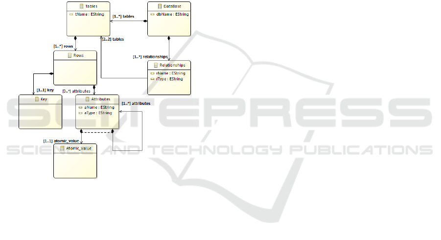
attribute whose value distinguishes a row from
all other rows of the same table,
R is a set of relationships. A relationship is a link
between two tables. In the generic logical model
there are only binary relationships between tables
.
Each relationship r ∈R between
and
is defined
as a tuple (N, Ty,
), where:
r.N is the relationship name.
r.Ty is the relationship type : Association,
Composition or Generalization.
r.Pr
= {pr
,pr
} is a set of two pairs. ∀i ∈
{1,2}, pr
= (t,cr), where pr
.t is a related
table and
.cr is the cardinality placed next
to t.
Metamodel of the proposed generic logical
model is shown in figure 3.
Figure 3: Target Metamodel.
4.3 Transformation Rules
R1: each CD is transformed into a database DB,
where DB.N = CD.N.
R2: each class c ∈ C is transformed into a table t ∈
DB, where t.N = c.N, IdentL
.N = IdentO
.N.
R3: each attribute a
∈ c.A is transformed into an
attributea
, where a
.N = a
.N, a
.Type = a
.C, and
added to the attribute list of its transformed
container t such as a
∈ t.A.
R4: each link l ∈ L between two classes c
and c
is
transformed into a relationship r ∈ R between two
tables t
and t
, where r.N = l.N, r.Ty = l.Ty et r.Pr
= l.Pr
, where t
and t
are the tables representing c
and c
.
R5: each link l ∈ L between n classes {c
,…,c
}
(n>=3) is transformed into (1) a new table t
, where
t
.N = l.N, and (2) n relationships {r
,…,r
}, ∀ i ∈
{1,..,n} r
links t
to another table t
representing a
related class c
, where r
.N = (t
.N)_(t
.N), r
.Type =
Association and r
.Pr
= {(t
, cr), (t
, cr)}.
R6: each association class c
between n classes
{c
,…,c
} (n>=2) is transformed like a link
between multiple classes (R5) using (1) a new table
t
, where t
.N = l.N, (2) n relationships
{r
,…,r
}, ∀ i ∈ {1,..,n} r
links t
to another table
t
representing a related class c
, where r
.N =
(t
.N)_(t
.N), r
.Type = Association et r
.Pr
=
{(t
, cr), (t
, cr)}. Like any other class, t
contain
also a set of attributes A, where t
.A = c
.A.
These transformation rules have been formalized
with QVT (figure 4.b), which is a standard defined
by OMG for expressing models transformation.
5 GENERIC MODEL TO
PHYSICAL MODEL
TRANSFORMATION
In this section we present the second transformation
in our approach UMLtoNoSQL (figure 2). It is in
charge of creating NoSQL physical models from the
proposed generic logical model.
5.1 Source: Generic Logical Model
(Logical PIM)
The source of this transformation is the target of the
previous UMLtoGenericModel transformation.
5.2 Target: NoSQL Physical Models
(PSMs)
To illustrate our approach, we have chosen three
NoSQL systems: Cassandra, MongoDB and Neo4j;
three well known NoSQL systems.
5.2.1 Cassandra Physical Model
In Cassandra physical model, KeySpace (KS) is the
top-level container that owns all the elements. It’s
defined as a tuple (N, F), where:
N is the keyspace name,
F is a set of columns-families. The schema of
each columns-family f ∈F is a tuple (N, Cl,
PrimaryKey), where:
f.N is the columns-family name,
f.Cl = {cl
,…,cl
} is a set of q columns that
will be used to define rows of f; each row can
have a variable number of columns. The
{XOR}
ICEIS 2017 - 19th International Conference on Enterprise Information Systems
252

schema of each column cl ∈ Cl is a pair
(N,Ty) where “cl.N” is the column name and
“cl.Ty” the column type.
f.PrimaryKey is a special column of f; it has a
name PrimaryKey
. N and a type
PrimaryKey
.Ty (standard data type).
PrimaryKey
identifies each row of f.
5.2.2 MongoDB Physical Model
In MongoDB physical model, DataBase (DB
) is
the top-level container that owns all the elements.
It’s defined as a tuple (N, Cll), where:
N is the database name,
Cll is a set of collections. The schema of each
collection cll ∈Cll is a tuple (N, Fl, Id), where:
cll.N is the collection name,
cll.Fl = Fl
∪ Fl
is a set of atomic and
complex fields that will be used to define
rows, called documents, of Cll; each
document can have a variable number of
fields. The schema of each atomic field fl
∈
Fl
is a tuple (N,Ty) where “fl
.N” is the field
name and “fl
.Ty” is the field type. The
schema of each complex field fl
∈ Fl
is
also a tuple (N, Fl’) where fl
.N is the field
name and fl
.Fl’ is a set of fields where Fl’
Fl.
cll.Id is a special field of cll; it has a name
Id
.N and a type Id
.Ty (standard data
type). Id
identifies uniquely each document
of cll.
5.2.3 Neo4j Physical Model
In Neo4j physical model, Graph (GR) is the top-
level container that owns all the elements. It’s
defined as a tuple (V, E), where:
V is a set of vertex. The schema of each vertex v
∈ V is a tuple (L, Pro, Id), where:
v.L is the vertex label,
v.Pro = {pro
,…,pro
} is a set of q properties.
The schema of each property pro ∈ Pro is a
pair (N,Ty), where “pro.N” is the property
name and “pro.Ty” the property type.
v.Id is a special property of v; it has a name
Id
.N, a type Id
.Ty and the constraint “Is
Unique ”. It identifies uniquely v in the graph.
E is a set of edges. The schema of each edge e ∈
E is a tuple (L, H
, H
), where:
e.L is the edge label,
e.H
and e.H
are the nodes related by e.
5.3 Transformation Rules
Several solutions can ensure the transformation of
the generic logical model into a NoSQL physical
model. We provide all transformation possibilities
available; the developer chooses the one that meets
better his needs. We note that the set of solutions
proposed in this section is not inclusive. More
marginal solutions may be considered.
5.3.1 To Cassandra Physical Model
R1: each database DB is transformed into a
keyspace KS, where KS.N = DB.N.
R2: each table t ∈ DB is transformed into a
columns-family f ∈ KS, where f.N = t.N,
PrimaryKey
.N = IdentL
.N.
R3: each attribute
∈ t.A is transformed into a
column cl, where cl.N =
.N, cl.Ty =
.Ty, and
added to the column list of its transformed container
f such as cl ∈ f.Cl.
R4: each relationship r ∈ R between two tables t
and t
is transformed by using references. Cassandra
does not support imbrication; the only solution we
can use to express relations between columns-
families consists in using references.
Depending on the relationship type, we distinguish
the following solutions:
if r = (N, Association, {(t
,cr),(t
,cr)}), we
transform r according to its cardinalities :
o if r = (N, Association, {(t
,*),(t
,1)}), there
are two possible solutions:
Solution 1: r is transformed into a new column cl
referencingf
(the columns-family representingt
),
where cl.N = (f
.N)_Ref et cl.Ty =
PrimaryKey
.Ty, and added to the columns list of
f
(the columns-family representingt
) such as cl ∈
f
.Cl.
Solution 2: r is transformed into a new multivalued
column cl referencingf
(the columns-family
representingt
), where cl.N = (f
.N)_Ref et cl.Ty =
set<PrimaryKey
>.Ty, and added to the columns
list of f
(the columns-family representingt
) such
as cl ∈ f
.Cl.
o if r = (N, Association, {(t
,1),(t
,1)}) : r is
transformed into a new column cl referencing
the columns-family f representing one of the
two related tables (t
or t
), where cl.N =
(f.N)_Ref et cl.Ty = PrimaryKey
.Ty, and
added to the columns list of the columns-
family f’ representing the other related table
such as cl ∈ f’.Cl.
Logical Unified Modeling for NoSQL Databases
253

o if r = (N, Association, {(t
,*),(t
,*)}), two
solutions could be considered:
Solution 1: r is transformed into a new multivalued
column cl referencing the columns-family f
representing one of the two related tables (t
or t
),
where cl.N = (f.N)_Ref et cl.Ty =
set<PrimaryKey
>.Ty, and added to the columns list
of the columns-family f’ representing the other
related table such as cl ∈ f’.Cl.
Solution 2: r is transformed into a new columns-
family f, where f.N = r.N, f.Cl = {cl
,cl
}, cl
.N =
(f
.N)_Ref, cl
.Ty = PrimaryKey
.Ty, cl
.N =
(f
.N)_Ref and cl
.Ty = PrimaryKey
.Ty, where f
and f
are the columns-families represent t
and t
.
if r = (N, Composition, {(t
,1),(t
,*)}) : in
composition relationship, cardinality of the
composite is 1 which means that a component
could be included in at most one composite at
a time and the cardinality of the component is
* which means that the composite could have
multiple components. To transform it, there
are two possible solutions:
Solution 1: r is transformed into a new multivalued
column cl referencing the columns-family f
representing the component (t
), where cl.N =
(f
.N)_Ref and cl.Ty = set <PrimaryKey
.Ty ,
and added to the columns list of the columns-family
f
representing the composite (t
) such as cl ∈ f
.Cl.
Solution 2: r is transformed into a new column cl
referencing the columns-family f
representing the
composite (t
), where cl.N = (f
.N)_Ref et cl.Ty =
PrimaryKey
.Ty , and added to the columns list of
the columns-family f
representing the component
(t
) such as cl ∈ f
.Cl.
if r = (N, Generalization, {(t
,1),(t
, null)}) : in
generalization relationship between a super-
table t
and a sub-table t
, cardinality of the
super-table is 1 which means that each
instance of the sub-table is also an indirect
instance of the super-table. Because of this,
generalization relationship is also informally
called "Is A" relationship. We transform it into
a new column cl referencing the columns-
family f
representing the super-table (t
),
where cl.N = (f
.N)_Ref et cl.Ty =
PrimaryKey
.Ty , and added to the columns
list of the columns-family f
representing the
sub-table(t
) such as cl ∈ f
.Cl.
5.3.2 To MongoDB Physical Model
R1: each database DB is transformed into a
MongoDB database
, where
.N = DB.N.
R2: each table t ∈ DB is transformed into a
collection cll ∈
, where cll.N = t.N et Id
.N
=IdentL
.N.
R3: each attribute
∈ t.A is transformed into a
field fl, where fl.N =
.N, fl.Ty =
.Ty, and added
to the field list of its transformed container cll such
as fl ∈ cll.
.
R4: a relationship r between two tables
and
could be transformed in MongoDB by using
references or imbrication. Depending on the
relationship type, we distinguish the following
solutions:
if r = (N, Association, {(t
,cr),(t
,cr)}), we
transform r according to its cardinalities :
o if r = (N, Association, {(t
,*),(t
,1)}), there
are two possible solutions:
Solution 1: r is transformed into a new field fl
referencingcll
(the collection representingt
),
where fl.N = (cll
.N)_Ref and fl.Ty = Id
.Ty, and
added to the fields list of cll
(the collection
representingt
) such as fl ∈ cll
.Fl
.
Solution 2: r is transformed into a new multivalued
field fl referencingcll
(the collection
representingt
), where fl.N = (cll
.N)_Ref and fl.Ty
= set<Id
>.Ty, and added to the field list of cll
(the collection representingt
) such as fl ∈ cll
.Fl
.
o if r = (N, Association, {(t
,1),(t
,1)}) : r is
transformed into a new field fl referencing the
collection cll representing one of the two
related tables (t
or t
), where fl.N =
(cll.N)_Ref and fl.Ty = Id
.Ty, and added to
the field list of cll’ representing the other
related table such as fl ∈ cll’.
.
o if r = (N, Association, {(t
,*),(t
,*)}), two
solutions could be considered:
Solution 1: r is transformed into a new multivalued
field fl referencing the collection cll representing
one of the two related tables (t
or t
), where fl.N =
(cll.N)_Ref and fl.Ty = set<Id
>.Ty, and added to
the field list of cll’ representing the other related
table such as fl ∈ cll’.Fl
.
Solution 2: r is transformed into a new collection cll,
where cll.N = r.N, cll.Fl = {fl
,fl
}, fl
.N =
(cll
.N)_Ref, fl
.Ty = Id
.Ty, fl
.N = (cll
.N)_Ref
and fl
.Ty = Id
.Ty, where cll
and cll
are the
collections representing t
and t
.
if r = (N, Composition, {(t
,1),(t
,*)}) : there
are three possible solutions:
Solution 1: r is transformed by embedding the
collection cll
representing the component (t
) in the
collection cll
representing the composite (t
),
where cll
∈ cll
.Fl
.
ICEIS 2017 - 19th International Conference on Enterprise Information Systems
254

Solution 2: r is transformed into a new field fl
referencing the collection cll
representing the
composite (t
), where fl.N = (cll
.N)_Ref et fl.Ty =
Id
.Ty , and added to the field list of the collection
cll
representing the component (t
) such as fl ∈
cll
.Fl
.
Solution 3: r is transformed into a new multivalued
field referencing the collection cll
representing the
component (t
), where fl.N = (cll
.N)_Ref and fl.Ty
= set <Id
.Ty , and added to the field list of the
collection cll
representing the composite (t
) such
as fl ∈ cll
.Fl
.
if r = (N, Generalization, {(t
,1),(t
, null)}) :
it’s transformed into a new field fl referencing
the collection cll
representing the super-table
(t
), where fl.N = (cll
.N)_Ref and fl.Ty =
Id
.Ty , and added to the field list of the
collection cll
representing the sub-table (t
)
such as fl ∈ cll
.
.
5.3.3 To Neo4j Physical Model
R1: each table t ∈ DB is transformed into a vertex v
∈ V, where v.L = t.N, Id
.N = IdentL
.N.
R2: each attribute
∈ t.A is transformed into a
property pro, where pro.N =
.N, pro.Ty =
.Ty,
and added to the property list of its transformed
container v such as pro ∈ v.Pro.
R3: Each relationship r between two tables t
and
t
is transformed into an edge e, where e.L = r.N,
e.H
= v
and e.H
= v
, where v
and v
are the
vertex representing t
and t
.
6 EXPERIMENTS
In this section, we first provide the implementation
of UMLtoGenericModel transformation as presented
in sections 4, and then we show how to generate
NoSQL physical models starting from the proposed
generic logical model.
6.1 Experimental Environment
We carry out the experimental assessment using: (1)
Eclipse Modeling Framework (EMF): a modeling
framework and code generation to support the
development of tools and model driven applications;
(2) Ecore: a metamodeling language that we used to
create our metamodels; (3) XML Metadata
Interchange (XMI): XML based standard for
metadata interchange. We use XMI to create models
as instance of metamodels; and (4) Query / View /
Transformation (QVT): the OMG standard for
models transformation.
6.2 UMLtoGenericModel
Transformation
Before proceeding to the implementation of the
transformation rules, first, we created Ecore
metamodels corresponding to the source (Figure 2)
and the target (Figure 3). The next step is to create
an instance of the source metamodel (Figure 4.a). In
parallel, we used QVT plugin to implement the
transformation rules (Figure 4.b); the comments in
the script indicate the rules used. Finally, we tested
the transformation by running the QVT script. The
execution of this script provides the generic logical
model (figure 4.c).
(a) : Source Model (excerpts).
(b) QVT Rules. (c) Target Model..
Figure 4: UMLtoGenericModel transformation.
6.3 GenericModeltoPhysicalModel
Transformation
The generic model proposed in this paper does not
imply a specific system. Consequently, several
NoSQL physical models could be generated starting
Logical Unified Modeling for NoSQL Databases
255

from it. Lack of place, we show only Cassandra
physical model (figure 5.b) generated from the
generic logical model (figure 4.a). An excerpt from
the QVT transformation script is shown in Figure
5.a.
(a) QVT Rules. (b) Cassandra Model.
Figure 5: GenericModeltoCassandraModel transformation.
7 RELATED WORK
To the best of our knowledge, there are only few
solutions that have dealt with NoSQL databases
conceptual modeling. Chevalier et al. (Chevalier,
2015) defined a set of rules to map a
multidimensional model into column-oriented and
document-oriented models. The links between facts
and dimensions have been converted using
imbrications. Although the transformation process
proposed by authors start from a conceptual level
(multidimensional model), this specific model is
different from the UML standard; it contains facts,
dimensions and one type of links only. Other studies
investigate the process of transforming relational
databases into HBase (Li, 2010) and MongoDB
(Vajk, 2013). However, the relational model does
not present the semantic richness of UML
(especially through the several types of relationships
between classes: association, composition,
generalization, etc.). Few works have presented
approaches to implement UML conceptual models
in NoSQL databases. Li et al. (Li, 2014) propose a
MDA-based approach to transform UML class
diagram into HBase. After building the source and
the target metamodels, the authors have proposed
mapping rules to realize the transformation from the
conceptual level to the physical level. These rules
are applicable to HBase, only. Daniel et al. (Daniel,
2016) describe the mapping between UML
conceptual models and graph databases via an
intermediate graph metamodel. These rules are
specific to graph databases used as a framework for
managing complex data with many connections.
Generally, this kind of NoSQL databases is used in
social networks where data are highly connected.
8 CONCLUSION AND
PERSPECTIVES
In this paper we have presented a MDA-based
approach to implement UML conceptual model
describing Big Data in NoSQL systems. Our
approach consists of a chain of transformations that
generate a generic logical model compatible with the
three types of NoSQL systems (column, document
and graph) and independent of a specific NoSQL
platform, which makes it easier to transform it into
several NoSQL physical models. As future work, we
plan to complete our transformation process and
propose a mapping for OCL expressions defined in
the conceptual model; queries languages provided
by NoSQL databases could be used for this.
REFERENCES
Angadi, A., Gull, K., 2013. Growth of New Databases &
Analysis of NOSQL Datastores. In IJARCSSE.
Cattell, R., 2011. Scalable SQL and NoSQL data stores. In
ACM SIGMOD Record.
Abelló, A., 2015. Big data design. In DOLAP.
Hutchinson, J., Rouncefield, M., Whittle, J., 2011. Model-
driven engineering practices in industry. In ICSE.
Li, C., 2010. Transforming relational database into HBase:
A case study. In ICSESS.
Douglas, L., 2001. 3d data management: Controlling data
volume, velocity and variety. Gartner.
Bézivin, J., Gerbé, O,. 2001. Towards a precise definition
of the OMG/MDA framework. In ASE.
Chevalier, M., El Malki, M., Kopliku, A., Teste, O.,
Tournier, R., 2015. How Can We Implement a
Multidimensional Data Warehouse Using NoSQL?. In
ICEIS.
Abadi, D., Madden, S., Hachem, N., 2008. Column-stores
vs. row-stores: How different are they really?. In
ICMD.
Li, Y., Gu, P., Zhang, C., 2014. Transforming UML class
diagrams into HBase based on metamodel. In ISEEE.
Daniel, G., Sunyé, G., Cabot, J., 2016. Mapping
conceptual schemas to graph databases. In ER.
Vajk, T., Feher, P., Fekete, K., Charaf, H., 2013.
Denormalizing data into schema-free databases. In
CogInfoCom.
main(){
Source.rootObjects()[DataBase]‐>
maptoKeySpace();
}
mapping
DataBase::toKeySpace():KeySpace{
name:=self.name;
columnsfamily:=self.tables‐>map
toColumnsFamily();
}
‐‐TransformingCtableto
ColumnsFamily
mappingCOLM
::Table::toColumnsFamily():Cassandr
a::ColumnsFamily{
name:=self.name;
column:=self.columns‐>map
toColumn();
}
‐‐TransformingAttributetoColumn
mappingCOLM
::Column::toColumn():Cassandra::Col
umn{
if(self.cType="Rid"){
ICEIS 2017 - 19th International Conference on Enterprise Information Systems
256
