
Process Architecture Enabling Object Orientation and Dynamic
Configuration for Small Embedded Devices
Dynamic Control of Processes and Communication Channels
Steffen Dalgard and Anders Liverud
SINTEF Digital, Smart Sensor Systems, Forskningsveien 1, Oslo, Norway
Keywords: Object Orientation, Software Architecture for Reuse, Task Control, Message Communication, Embedded
Resource Constrained Software, Real-time Systems.
Abstract: Embedded systems pose challenges such as limited memory and power budget. The list of mandatory
functionality like connectivity, availability and remote configuration increase the software complexity and
requires a more dynamic behaviour. This paper shows how to introduce object orientation to achieve dynamic
configuration of processes and communication channels, better usage of RAM and more portable source code.
This is implemented by a limited use of C++ without libraries in coexistence with existing C code.
1 INTRODUCTION
The market for consumer electronics is continuously
growing and vast amount of processors in the world
are found in embedded applications. The gap between
typical applications and embedded applications is
also diminishing. The application areas are battery
operated wearable devices (watches, GPS, medical
sensors, sports sensors). Embedded systems pose
challenges such as limited resources like memory and
power budget, the need for energy conservation for
battery-operated devices and a small form factor.
Development for resource-constrained devices
(RCD) has not been able to follow all the trends of
regular computers. The availability of better batteries
and platforms with lower power consumption tends to
max out total operating time and not adding
functionality. The list of mandatory functions like
connectivity, availability and remote management,
has increased as part of the IOT trends. To meet these
demands a more dynamic behaviour is needed. RCDs
have traditionally been static by nature due to lack of
full operation systems (OS) and management
interfaces. Many RCDs are using an embedded OS
with real-time scheduling of multiple processes
compiled in a monolithic block. Basic services like
semaphores, timers, events, message queues etc. are
supported. Advanced services like file systems,
download of separate tasks and TCP protocol stack
are normally not supported.
As the functional complexity increases, the need for
a better software architecture arise. A very common
architecture for RCDs is a fixed set of process
instances that are globally known. Communication
between processes are done by accessing global
message queues and variables. This architecture does
not scale for reuse of code. By separating process
functionality and how processes are connected
(configuration) it is possible to make reusable
processes and an architecture that scales. Multiple
process instances can share code that can be used in
different configurations.
This paper introduces an RCD architecture for
processes as objects enabling i) dynamic control of
instantiation using µC/OS (Labrosse, 2003) and ii)
dynamic control of communication links.
The introduction of object-oriented design (OOD)
enables reuse of processes as objects much easier than
in traditional RCD architectures. The main obstacle
has been the communication links. By introducing
dynamic communication links as an abstraction, the
processes can be reused between designs, and only
the links need to be configured differently. This
enables multiple configurations in the same binary
code utilizing RAM and ROM memory more
efficiently that a traditional static architecture. The
configurations can be dynamically activated without
downloading new binary images. The architecture
can coexist with the traditional RCD architecture
without conflicts; hence, it is possible to use legacy
processes with the new architecture.
Dalgard, S. and Liverud, A.
Process Architecture Enabling Object Orientation and Dynamic Configuration for Small Embedded Devices - Dynamic Control of Processes and Communication Channels.
DOI: 10.5220/0006435000410048
In Proceedings of the 7th International Joint Conference on Pervasive and Embedded Computing and Communication Systems (PECCS 2017), pages 41-48
ISBN: 978-989-758-266-0
Copyright © 2017 by SCITEPRESS – Science and Technology Publications, Lda. All rights reserved
41

This RCD architecture is a variant of the mediator
design pattern (Gamma, 1995) where the
communication is directed through a port abstraction.
This paper targets small RCD devices limited to 128
kByte program memory (ROM) and 64 kByte data
memory (RAM). An architecture offering dynamic
creation of processes and communication channels
portable to many targets is shown.
The paper is organized by a state of the art section,
followed by a description of the process architecture.
Then implementation details and a test setup is given,
before test results are presented and discussed in the
conclusion.
2 STATE OF THE ART
Operating Systems (OS) suitable for resource-
constrained devices typically store much of their
configuration in ROM. This is done mainly for two
purposes: i) minimize the use of expensive RAM
memory and ii) minimize the risk that data is
overwritten by an erroneous application. The OS
gives the application programmer easy access to
hardware features. It also provides services that allow
implementing of timing sensitive code. The build
environment is normally in a host environment that is
different from the target environment, using cross
compilation. The OS is normally statically linked
with the application at compile time and downloaded
as a binary file to the device. For more details on
embedded systems see (Zurawski, 2006).
Download / upgrade of new binary code is handled
using proprietary connections and protocols and a
physical connection is usually required. Upgrades
over the air are complicated due to fault scenarios.
Multiple levels of fault detection are needed to assure
correct binary code. Storage of multiple images is
usually implemented as a fallback.
2.1 Full Scale OS
Dynamic adaptation of processes can easily be
achieved on computers with a full operation system
where programs can be stored on a disk and started
from the command prompt. For devices that are more
powerful this can be implemented using a down-
scaled version of Linux. To achieve such flexibility
the programs have to execute from RAM, while ROM
is used as a read only (RO) filesystem. The RAM is
usually managed using a Memory Management Unit
(MMU) to isolate applications from each other and
from the hardware. Such devices require more power
and tend to have higher weight and price.
2.2 Software Components
Independent modules that can be loaded or updated
individually are often called software components. To
achieve this the modules must be dynamically linked
before they can access the OS. Examples of such
systems are given by (Dunkels, Finne, Eriksson, &
Voigt, 2006), (Taherkordi, Loiret, Rouvoy, &
Eliassen, 2013) and (Hänninen et al., 2008). Such
designs usually are tightly connected to specific
object code formats and have special tools for
dynamic linking that limit portability. When
executing from ROM or FLASH memory it is not
possible to update another component in the same
device. For such updates, multiple FLASH devices
are required and this is commonly not supported on
smaller System on Chip (SoC) devices.
2.3 Static Configuration
Static configuration means that the configuration is
fixed at compile time. The source code can be
modularized using interfaces, and the interfaces are
connected by use of a configuration. The source code
can be native C-code as for the Koala project (van
Ommering, 1998) or derivate of C-code like
languages like NesC in TinyOS (Amjad, Sharif,
Afzal, & Kim, 2016) and (Gay, Levis, & Culler,
2007). Common for these systems is that number of
instances and the RAM and ROM memory usage is
decided at compile time. This is based on the
assumption that dynamic memory allocation is not
used during task execution.
2.4 Typical µC-OS Application
In a typically µC-OS application (Labrosse, 2003)
message queues are used for asynchronous
communication between concurrent OS processes.
Each OS process has its own message queue that is
globally known. The program is a monolithic
construction. Each task knows to which other tasks to
communicate. The communication is based on a set
of globally predefined message IDs. Due to the
unidirectional communication pattern, identification
of message originator has to be supported in the
message definition as an explicit field or deduced
from the message type. Without this information, it is
not possible to reply to the originator. The result is a
static flat communication structure where all
communication dependencies are intertwined. The
communication pattern is defined at compile time.
Normally the different processes (ProcA … Proc_n)
are started as separate OS processes with allocated
PEC 2017 - International Conference on Pervasive and Embedded Computing
42
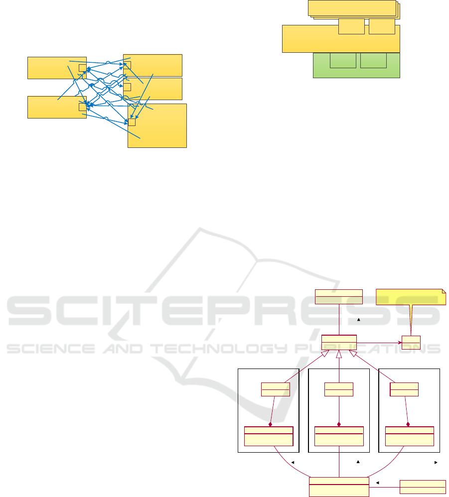
stack area by the main() function at start-up. Each
task is a separate c-code module with its local (static)
variables and message queue. The architecture is
shown in figure 1.
Process B
q
Process A
q
|
Process C
q
Process D
q
Process E
q
Figure 1: Process architecture using global queues.
If an additional instance of a process is needed the flat
structure does not support this as a concept. The new
instance needs its own OS task and a set of local
variables and a message queue. Because each task has
hardcoded communication, it is not possible to start a
new instance sharing the same code. The process
source code has to be changed / duplicated. This will
force an update/rewrite of several tasks when new
functionality is added. It is possible to have different
operational configurations deciding the mode of the
device. This is typically done by tests inside the
different processes. Due to static variables and the
fact that all processes are started at start-up the RAM
usage will be the superset of all configurations. To
reduce RAM usage, the unused functionality has to be
removed from the build. Dynamic memory allocation
(heap) is normally avoided due to complexity to
assure real-time response. Fragmentation over time is
a problem and there is no operator to help out if the
device fails. Some designs are using dedicated pools
to assure predictable response.
3 DESCRIPTION OF THE
PROCESS ARCHITECTURE
The new architecture shown in figure 2 is based on a
static build (one binary image) consisting of a set of
processes and an operation system (OS) with services
for task scheduling and message queue handling. A
configuration manager is added to dynamically
manage the processes and their communication. This
enables multiple process and communication
configurations to be specified after the build is
deployed on an RCD.
Operating system
Process
Configuration manager
Task
scheduler
Message
queues
ProcGen Ports
Process
Process
Figure 2: The new process architecture.
3.1 Processes Creation
Multiple process instances require handling of
instance variables. A process should not require any
RAM resources before creation (instantiation). By
controlling which process to create the usage of the
restricted RAM resources is controlled. Dynamic
memory management adds an unwanted uncertainty.
This is handled by allocating all the needed instance
memory at process creation. Dynamic memory
creation during process execution is normally
avoided due to unpredictable response time and
fragmentation. However, the architecture does not
impose any restrictions on usage of dynamic memory
allocation for advanced process logic.
ProcessA Class ProcessB Class ProcessC Class
ProcessA_Factory
static Instanti ate()
static GetProcessInfo()
ProcessA
ProcessB_Factory
static Instanti ate()
static GetProcessInfo()
ProcessB
ProcessC_Factory
static Instantiate()
static GetProcessInfo()
ProcessC
CommandParser
ConfigurationManager
Insta ntia te()
GetProcessInfo()
OperatingSystem
TaskCreation()
ProcessGen
TaskCreate()
Ports
Number of ports is given
by process factory
creates
many
1
creates
many
1
creates
many
1
create instance
create instance
create instance
calls
creates process
Figure 3: Process creation using factories.
When creating a new process instance there are many
process specific parameters to control like stack size
and number of ports. This is handled using the factory
pattern described in (Gamma, 1995). Each process
type have their own static factory method that handles
process specific parameters as shown in figure 3.
A configuration manager interfaces a command
Process Architecture Enabling Object Orientation and Dynamic Configuration for Small Embedded Devices - Dynamic Control of Processes
and Communication Channels
43
parser, and keeps track of all process types and
created processes.
The operating system has to support dynamic process
creation. This rule out static operating systems where
a complete process setup is given at compile time.
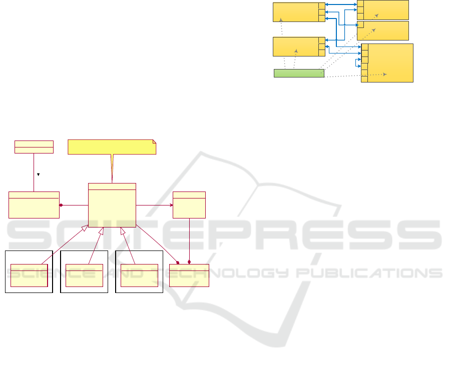
3.2 Processes Generalisation and
Control
All process types are based on a process
generalisation providing methods to manage all
process instances (start/stop) and communication
channel management (create/delete). This maximises
reuse of management code for all process types. It
also simplifies implementation of new process types.
The configuration manager is accessing the
generalized methods when controlling process
instances as shown in figure 4.
ProcessA Class ProcessB Class ProcessC Class
ProcessA
TaskMain()
GetTaskTyp eName()
GetPortInfo()
ProcessB
TaskMain()
GetTaskTypeName()
GetPortInfo()
ProcessC
TaskMain()
GetTaskTypeName()
GetPortInfo()
CommandParser
OperatingSystem
TaskExecution()
MessageSend()
QueueWait()
ConfigurationManager
Resume()
Suspend()
CreateChanne l()
DeleteChannel()
ProcessGen
virtua l TaskMain()
virtua l GetTaskTy peName()
virtual GetGetPortInfo()
Resume()
Suspend()
GetTaskInstanceName()
CreateBidirCha nnel()
DeleteChannel()
Ports
SetPortParams()
GetRemotePort()
SendMsg()
ReceiveWaitMsg()
Virtual class extended by all processes
Used for control of instances
1
controls
1
many
executes
1
many
uses
many
1
calls
Figure 4: Process management using ProcessGen.
3.3 Communication Links
All processes are communicating using channels
connected by ports. The ports are part of the process
generalization and reused by all process types. The
number of ports for a specific process type is defined
by its static factory. Each process instance has its own
input queue shared for messages to all ports as shown
in figure 5. To handle a shared queue the message
payload must provide information about destination
port number. General channels are bidirectional,
which means sending a message to the incoming port
will send it back to the originator. This makes it easy
to implement client server design interaction model
as described in (Zurawski, 2006) chapter 2.2. The port
pair using a channel needs to use a common set of
messages, while different port pairs may use different
messages or protocols. The port concept is essential
to configure the communication channels. The code
inside the process only relate its communication to
the ports. The number of ports and their functionality
are specific for each process. This makes an
abstraction of the communication channel and
enables multiple instances and different
configurations.
Process B
p1
p2
p3
Configuration manager
Process A
p1
p2
p3
|
Process C
p1
Process D
p1
p2
p3
p4
p5
p6
Process A
p1
p2
p3
Figure 5: Process architecture using channels.
4 IMPLEMENTATION AND TEST
SETUP
4.1 Targets, OS and Compilers
Based on an existing codebase and experience, our
experiments were done using µC/OS-II and µC/OS-III.
This is a portable, pre-emptive real-time multitasking
operating system kernel for microcontrollers. It is
ported to a large number of microcontrollers and
processor architectures. It provides semaphores, event
flags, mailboxes and queues, time management and
memory block management. The footprint of the
kernel is low and can be configured from 5Kbytes to
24Kbytes. The operating system kernel was initially
written as a teaching tool and later developed as a
commercial product. It is free for educational and non-
commercial use.
In the setup of the process architecture, we are using
the kernel for multitasking and queues for message
communication. The architecture does not limit the
introduction of other OS functions when required.
The operating system µC-OS is a pure C component
with an extensive library that requires all APIs to be
accessible for C-code modules.
For the process architecture, multiple instances of a
process are important from a reuse point of view. The
current concept of using a (C-code) module with
statically defined process variables does not support
multiple instances. It must be easy to make equal or
almost equal processes without duplicating and
rename code. In order to have multiple instances, all
process variables have to be instantiated for each
instance. This is possible if all instance variables are
allocated when the process is created enabling shared
code and unique variables for each instance. A natural
PEC 2017 - International Conference on Pervasive and Embedded Computing
44
choice was to introduce a restricted subset of C++.
We needed the class concept to support encapsulation
and instantiation, but we did not add the C++
libraries. The concept is to embed C-code into C++
classes. The amount of C++ functionality to use
should not be enforced by the process architecture.
For memory allocation we made a dedicated static
array that was used when creating processes. The C++
'new' method was customized to use the static array.
We found easier to control and monitor than using the
system heap. The total memory available from the
heap is not an exact figure in many systems, since
heap and stack grow towards each other. This does
not make sense in a multitasking system with one
stack for each process.
4.2 The Processgen C++ Class
Hierachy
The ProcessGen is a virtual class that hides
interaction with the OS and the command manager. It
hides the differences between µC-OS-II and µC-OS-
III when it comes to process creation and managing
processes. The process functionality is implemented
as sub-classes that are portable between the two OSes.
The class is a placeholder for all process information
needed by the OS including allocated stack and
queue. It also has methods to create, resume and
suspend of the process.
Methods for setup and deletion of communication
channels are placed in ProcessGen because this
requires information about tasks and ports. The ports
themselves are part of a separate class. The Port class
instance is member of ProcessGen.
Two virtual methods are used to access process type
specific functionality. The TaskMain() is the entry
point for process execution. This method is called
once when the process is activated, however it
normally never returns. It consists of a while loop
waiting for a message from the queue, processing it
and generating some result. The GetTaskType() is
used to identify the process type. Together with static
information about the ports for that process type,
communication channels can be configured.
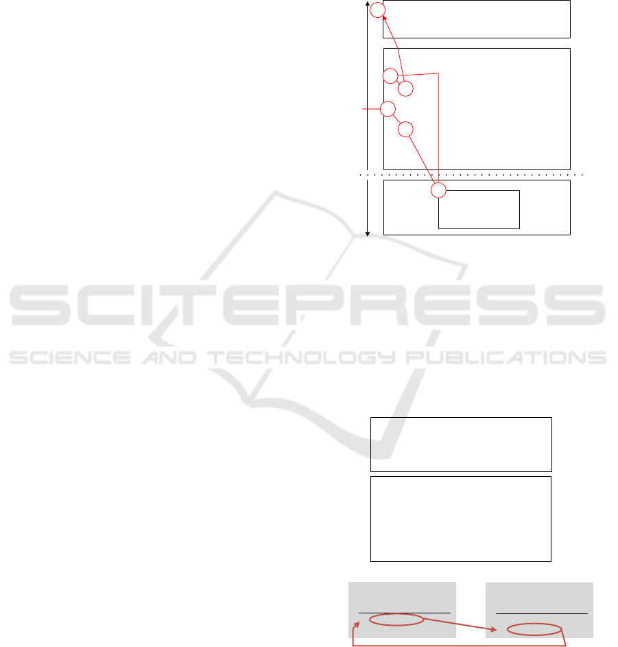
The µC-OS is implemented in C and has no specific
support for C++. Our selected compilers (IAR and
GCC) support both C and C++ interaction when using
"Extern-C" calling convention. This makes it possible
to call "C-functions" bridging code compiled for C
and code compiled for C++. The challenge is that C
does not have the class concept. This excludes C code
calling class methods. To enable µC-OS to handle
C++ processes a static adapter function has been used.
The flow using the function is shown in figure 6.
When calling the OS function osTaskCreate() we pass
a start-up function pointer and a custom value. The
custom value is passed as argument to the start-up
function when the process is activated. This can be
used to pass a class pointer to the adapter function.
By using this setup the C code can start and manage
the C++ process classes as normal C processes.
Class ProcessA : public ProcessGen{
TaskMain()
}
Class ProcessGen {
virtual TaskMain();
static Adapter( arg) {
((ProcessGen*)arg->TaskMain();
}
TaskCreate() {
osTaskCreate(
ProcessGen::Adapter,
this);
}
}
UC-OS
C++ C
osTaskCreate(
startFp,
arg)
3
1
2
4
5
6
Figure 6: Process create interacting C++ and C.
4.3 The Port C++ Class
The Port class is representing the port abstraction that
is used for sending and receiving messages. The
number of ports and their names are process specific.
This is important to keep the memory consumption as
low as possible. Each port have information about the
far end (process and port number).
Class ProcessGen{
:
PortClass Ports;
:
}
Class PortClass {
:
struct port_element {
ProcessGen *RemProc;
int16_t RemPortNum;
} *PortArr;
:
}
Proc "P1"
PortArr
Idx RemProc RemPortNum
0 P2 1
1 P3 2
Proc "P2"
PortArr
Idx RemProc RemPortNum
0 P3 4
1 P1 0
Figure 7: Creating channels by connecting ports.
The relation is one direction, from local port to far end
port. To establish a bidirectional connection both
ports have to be configured in antiparallel as shown
Process Architecture Enabling Object Orientation and Dynamic Configuration for Small Embedded Devices - Dynamic Control of Processes
and Communication Channels
45
in figure 7. This makes it possible to also represent
unidirectional connections, while a multicast (one to
many) is not possible. When keeping the relations to
one-to-one the architecture scales well since the port
allocation follows the process allocation.
4.4 Configuration Script
Information about task types, port names and roles,
running tasks and channels can be read by using RCD
commands in a simple serial console interface. The
commands available are:
task
instantiate <task_name>
<instance_name>
<param1>
...
<paramN>
active - List active task instances
memory - RAM used by task instances
run [instance_name] (default all)
stop <instance_name>
types - List task types
zero <instance_name>
channel
create <local_instance_name>
<local_port_name>
<remote_instance_name>
<remote_port_name>
delete <local_instance_name>
<local_port_name>
list
The commands listing tasks and channels do span an
arbitrary number of lines. The start and end of the
listing is indicated as shown here:
HEADS->norm> task types
Listing of supported task types
Task type=Requester PO(0):p0
Task type=Server PO(0):p0 PO(1):p1
Task type=CtrlPorts RO(0):ctrl_mob
RO(1):ctrl_bt RO(2):ctrl_spi
Task type=Receiver PO(0):rx0 PO(1):rx1
PO(2):rx2 PO(3):rx3
Task type=Sender RO(0):tx0 RO(1):tx1
RO(2):tx2 RO(3):tx3
End of task type listing
All device specific information is available from the
device. To start a process only a few commands are
required as shown here:
task i Receiver rx
task i Sender tx
channel c tx tx0 rx rx0
task run
4.5 Test Setup
The dynamic process architecture is tested for use of
resources, execution overhead as well as RAM and
static code memory usage. Two small RCD systems
are used for the testing; an Energy Micro (now Silicon
Labs) EFM32 based sensor (www.silabs.com) with
IAR Embedded Workbench for ARM version 7.40
(www.iar.com) as well as a Cypress PSoC5
development kit (www.cypress.com) with PSoC
Creator v. 4.0. The testing is done based on the
following code levels:
1. Basic systems, legacy µC-OSII/III system with
operational processes without test processes
added.
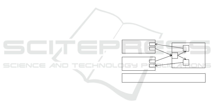
2. Basic systems with three additional processes,
R1
S
, R2
S
and S
S
. R1
S
and R2
S
are coded to send
µC-OS-II/III messages to S
S
, while S
S
will return
message to the sender (R1
S
or R2
S
). R1
S
and R2
S
can be initiated to send messages to S
S
in a loop
by a console command. The elapsed time for the
complete loop is measured. The architecture is
illustrated in figure 8. This level will show how
much it costs to add the new static processes to
the build.
Q
Q
H1
H2
S
S
R1
S
Q
R2
S
Basic systems, uC-OSII/III with operational processes
Figure 8: Static architecture with two processes sending
µC-OS-II/III messages and one process returning messages
to the sender.
3. Same static RCD architecture, compiled with
C++ compiler instead of plain C compiler. This
level will show how much it costs to enable C++
compilation and linking.
4. Dynamic architecture as shown in Figure 9,
however the S
D
object and class is removed.
5. Dynamic architecture as shown in Figure 9,
however the R
D
objects and class are removed.
6. Complete dynamic architecture as shown in
Figure 9.
The static and dynamic architectures (level 2 and
level 6) are tested for execution speed by sending
messages in a loop (60000) and measuring the
elapsed time by use of the microcontroller clock.
Each tests are repeated 10 times to ensure no time
variations.
PEC 2017 - International Conference on Pervasive and Embedded Computing
46
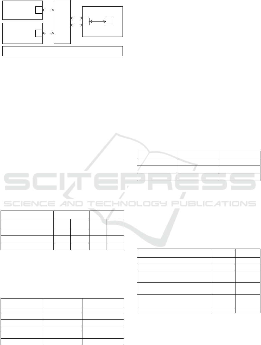
Q
Q
Q H
S
D
R
D
R
D
P0
Common
Channel
setup
Config
manager
P0
P0
P1
Basic systems, uC-OSII/III with operational processes
Figure 9: Dynamic architecture with two instances of
process RD sending µC-OS-II/III messages and one process
SD returning messages to the sender, dynamic channel
configuration.
The ROM memory usage for each level is recorded
from the map-file from the linker. The RAM usage is
also recorded from the map-file for the static code,
and through a combination of map-file and console
commands for dynamic RAM usage.
5 RESULTS
The execution time for sensor running Energy Micro
EFM32 (32 MHz) and Cypress PSoC5 (60 MHz) for
60000 loops is shown in table 1. The major reason for
increased execution time is due to the port class doing
lookup between port number and queue to find where
to send the message.
Table 1: Execution time results.
Architecture EFM32 PSoC5
Process R1 R2 R1 R2
Static architecture 1085 1085 1489 1500
Dynamic architecture 1147 1137 1551 1546
Difference 5.7% 4.7% 4.2% 3.1%
The additional ROM memory required for the
different steps in section 4.5 is shown in table 2.
These results are relative to code level 1 at 61288
bytes for EFM32 and 65792 for PSoC5.
Table 2: ROM memory overhead.
Code level EFM32 PSoC5
Level 1 0 0
Level 2 +2108 +2816
Level 3 +2108 +2816
Level 4 +8328 +10240
Level 5 +8232 +10240
Level 6 +8848 +11264
The increase in ROM usage for level 2 and 3 is due to
the added processes R1
S
, R2
S
and S
S.
For level 4, 5
and 6 it is more complex; when adding a process the
common code for i) ProcessGen and Port classes that
bring in reusable code for handling dynamic
processes and dynamic channels and ii) the
configuration manager handling all the commands.
The different components can be calculated based on
the following equations:
Size
L4
=Size
Common
+Size
RD
(1)
Size
L5
=Size
Common
+Size
SD
(2)
Size
L6
=Size
Common
+ Size
RD
+Size
SD
(3)
The component contribution when applying the
equations 1, 2 and 3 are shown in table 3. This shows
that the ROM code for building one process type is
about the same for the static and the dynamic
architecture. For the dynamic architecture common
ROM code to handle the architecture features is
added once in the build.
Table 3: Calculated ROM details.
Component EFM32 PSoC5
Size
Common
7712 9216
Size
SD
616 1024
Size
RD
520 1024
Table 4 shows that the RAM overhead for level 4 to
6 were dynamically allocated when the processes
were created. The total RAM consumption for level 2
and 6 are in the same range. It was expected that RAM
usage at level 6 were slightly higher than on level 2
due to more process information to keep in RAM. We
did not find out why this not was the case for PSoC5.
Table 4: RAM overhead relative to code level 1.
Code level EFM32 PSoC5
Level 1 total 0 0
Level 2 and 3 addition +1670 +2112
Level 4 to 6 not including
dynamic RAM use (see below).
+93 +96
Level 4a dynamic RAM use,
single R task
+784 +628
Level 4b dynamic RAM use,
two R tasks
+1568 +1256
Level 6 dynamic RAM use +2360 +1892
6 CONCLUSION AND
DISCUSSION
The architecture was succsesfully tested for both
dynamic creation of processes and communication
Process Architecture Enabling Object Orientation and Dynamic Configuration for Small Embedded Devices - Dynamic Control of Processes
and Communication Channels
47

channels. It was ported to two differnt compilers and
two different OS variants.
The overhead for the introduction of the C++
compiler is very low. The usage of C++ libraries
causes added cost. In our use of objects for
encapsulation and inheritance, there were no use of
additional libraries. We got increased portability and
maintainability.
We found that the Cypress PSoC5 IDE had no support
for C++ libraries, but it was easy to add compiler
directives to enable C++ compiler functionality. IAR
had support for embedded C++ with a limited support
for C++ libraries.
We made a set of base classes hiding the differences
between µC-OS-II and µC-OS-III. The classes
effectively hid all differences managing processes
and message communication. The process
functionality was implemented as sub-classes that are
portable between the two OSes.
The architecture will enable ROM code with
processes for several application variants. The device
can be enabled with one application variant by use of
a script or remote commands. This reduces the need
for downloading new code when changing between
application variants. Downloading code costs energy,
thus the architecture can provide increased
operational battery time.
The architecture can simplify code generation from
design specific languages like ThingML (Harrand,
Fleurey, Morin, & Husa, 2016). ThingML among
other tools are modelling objects using message based
communication. When using the port concept from
the architecture, the code generation from such a tool
is simplified due to the concept similarities such as; i)
many object instances and ii) communication using
channels. The architecture also makes remote
configuration possible by interfacing tools like
Kevoree (Tricoire et al., 2016). Then sensor devices
can be managed using the same tools as cloud
services. Future work will focus on automatic
management of messages reducing manual interface
coding. Today much time is used writing and
maintaining proxy functions dedicated to each
message type. Automating this process will save
coding time and reduce time used for debugging.
ACKNOWLEDGEMENTS
This work has been supported by EU FP7 HEADS
(grant agreement: 611337) project.
REFERENCES
Amjad, M., Sharif, M., Afzal, M. K., & Kim, S. W. (2016).
TinyOS-New Trends, Comparative Views, and
Supported Sensing Applications: A Review. Ieee
Sensors Journal, 16(9), 2865-2889. doi: 10.1109/
Jsen.2016.2519924
Dunkels, A., Finne, N., Eriksson, J., & Voigt, T. (2006).
Run-time dynamic linking for reprogramming wireless
sensor networks. Paper presented at the Proceedings of
the 4th international conference on Embedded
networked sensor systems, Boulder, Colorado, USA.
Gamma, E. (1995). Design patterns : elements of reusable
object-oriented software. Reading, Mass.: Addison-
Wesley.
Gay, D., Levis, P., & Culler, D. (2007). Software design
patterns for TinyOS. Acm Transactions on Embedded
Computing Systems, 6(4). doi: Artn 22 10.1145/
1274858.1274860
Harrand, N., Fleurey, F., Morin, B., & Husa, K. E. (2016).
ThingML: a language and code generation framework
for heterogeneous targets. Paper presented at the
Proceedings of the ACM/IEEE 19th International
Conference on Model Driven Engineering Languages
and Systems, Saint-malo, France.
Hänninen, K., Mäki-Turja, J., Nolin, M., Lindberg, M.,
Lundbäck, J., & Lundbäck, K. L. (2008). The rubus
component model for resource constrained real-time
systems. Paper presented at the SIES'2008 - 3rd
International Symposium on Industrial Embedded
Systems.
Labrosse, J. J. (2003). Embedded Real-Time Operating
System μC/OS-II.
Taherkordi, A., Loiret, F., Rouvoy, R., & Eliassen, F.
(2013). Optimizing Sensor Network Reprogramming
via In Situ Reconfigurable Components. Acm
Transactions on Sensor Networks, 9(2). doi:Artn 14
Doi 10.1145/2422966.2422971
Tricoire, M., Barais, O., Leduc, M., Bourcier, J., Fouquet,
F., Nain, G., Ieee. (2016). KevoreeJS: Enabling
dynamic software reconfigurations in the Browser.
Proceedings 2016 19th International Acm Sigsoft
Symposium on Component-Based Software
Engineering, 49-58. doi:10.1109/cbse.2016.20
van Ommering, R. (1998) Koala, a component model for
consumer electronics product software. Vol. 1429.
Lecture Notes in Computer Science (including
subseries Lecture Notes in Artificial Intelligence and
Lecture Notes in Bioinformatics) (pp. 76-86).
Zurawski, R. (2006). Embedded systems handbook. Boca
Raton: Taylor & Francis.
PEC 2017 - International Conference on Pervasive and Embedded Computing
48
