Object Oriented Structure from Motion: Can a Scribble Help?
Rahaf Rahal
1
, Daniel Asmar
1
, Elie Shammas
1
and Bernard Ghanem
2
1
Department of Mechanical Engineering, American University of Beirut, Beirut, Lebanon
2
King Abdullah University of Science and Technology, Thuwal, Saudi Arabia
Keywords:
Structure from Motion, Interactive Image Segmentation, Object Reconstruction.
Abstract:
The concept of anywhere anytime scanning of 3D objects is very appealing. One promising solution to extract
structure is to rely on a monocular camera to perform, what is well-known as Structure from Motion (SfM).
Despite the significant progress achieved in SfM, the structures that are obtained are still below par the quality
of reconstruction obtained through laser scanning, especially when objects are kept as part of their background.
This paper looks into the idea of treating points in the scene non-uniformly, in an attempt to give more weight
to the objects of interest. The system presented utilizes a minimal user interaction, in the form of a scribble,
to segment the pertinent objects from different views and focus the reconstruction on them, leading to what
we call Object Oriented SfM (OOSfM). We test the effect of OOSfM on the reconstruction of specific objects
by formulating the bundle adjustment (BA) step in three novel manners. Our proposed system is tested on
several real and synthetic datasets, and results of the different formulations of BA presented are reported and
compared to the conventional (vanilla) SfM pipeline results. Experiments show that keeping the background
points actually improves the reconstructed objects of interest.
1 INTRODUCTION
From the early ages, humans have always striven to
capture and reproduce the shapes of objects around
them; whether for religious or artistic purposes, the
millions of sculptures of both animate and inanimate
objects that abound around us are proof of this natu-
ral desire. In our modern day, this desire is ever so
strong and, in addition to its artistic appeal, the de-
sire to generate 3D models is product-driven. With
the advent of 3D scanners, Computer Aided Design,
and Computer Aided Manufacturing, the replication
of 3D objects has become accessible to the general
public. Example applications include the burgeoning
field of augmented and virtual reality, in which accu-
rate scans of the as-is object is required before aug-
menting it with any virtual addition.
Lasers have typically been the instruments of
choice for scanning objects. They are relatively accu-
rate, and robust to varying lighting conditions; howe-
ver, lasers are not readily available everywhere and
they are relatively expensive. Furthermore, for large
scenes, the setup of lasers at different vantage points
necessary for covering the entire scene can be quite
time-consuming. Stereo cameras can also be used
for scanning objects, but usually do not produce very
good results because of the inevitable holes that are
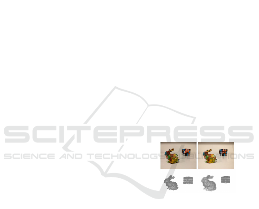
Figure 1: Concept of object oriented SfM (OOSfM): by fo-
cusing on different parts in the image, does SfM produce
better or worse quality objects than the vanilla SfM? The
objects selected and shown in focus (bunny on the left, cube
on the right) and their corresponding sought-after recon-
structions (bottom row).
left in the models because of the frequent unrelia-
ble disparity values obtained in stereopsis. As anot-
her alternative, monocular cameras can also be used
for scanning, using a technique commonly known as
Structure from Motion (SfM), where both the scene
structure and the camera trajectory inside the scene
during scanning are estimated. SfM offers many ad-
vantages: first, it relies on a single camera; most pe-
ople today have access to a camera in their smart pho-
nes, and by adding the required software, these devi-
ces easily turn into low-cost 3D scanners. Secondly,
monocular cameras possess a relatively large field of
Rahal, R., Asmar, D., Shammas, E. and Ghanem, B.
Object Oriented Structure from Motion: Can a Scribble Help?.
DOI: 10.5220/0006596005410548
In Proceedings of the 13th International Joint Conference on Computer Vision, Imaging and Computer Graphics Theory and Applications (VISIGRAPP 2018) - Volume 5: VISAPP, pages
541-548
ISBN: 978-989-758-290-5
Copyright © 2018 by SCITEPRESS – Science and Technology Publications, Lda. All rights reserved
541

view, both in depth and width, which ultimately re-
sults in the ability to scan large areas (Frahm et al.,
2010). Unfortunately, SfM also suffers from many
disadvantages. First, since the technique relies on a
monocular camera, the models that are obtained are
to an unknown scale. Second, applying the vanilla
SfM to an entire image generates reconstructions with
low accuracies, which, in their untouched form, are
not accurate enough to be built upon for applications
in computer graphics, such as in building the compu-
ter models for 3D printing, or for scanning outdoor
structures in augmented reality applications. In many
cases, manual labor-intensive post-processing of the
point cloud is necessary before it can be really used
in practice.
The objective of this work is to tackle the idea of
focused reconstruction. To do so, we suggest different
SfM variants, which will use a minor input from the
user with the aim of reconstructing specified objects
in the scene, while maintaining an acceptable recon-
struction quality for the remaining parts in the scene.
We qualify this concept as an Object-Oriented SfM
and refer to it hereafter as OOSfM (see Fig. 1).
This paper thus presents a set of object oriented
SfM variants, and studies whether it is possible to im-
prove the structure estimate of select objects in the
scene, while maintaining the background, albeit at a
lower (yet controlled) quality. There are three main
contributions in this work. (1) We present an object
tracking system that is developed for localizing the
object of interest in each image of a sequence of ima-
ges. After the user manually identifies the object of
interest in the first image, it is automatically detected,
and its boundaries segmented in subsequent images.
(2) By formalizing the bundle adjustment part of SfM
in three different ways, we attempt to put more weight
in the solution on the object of interest, and compare
the output to the traditional SfM result to test whether
the scribble could be of a help to the reconstruction
process. (3) Based on the results of our experiments,
we prove the inability of the re-projection error me-
tric to capture the actual reconstruction error when the
object of interest is considered rather than the entire
scene.
2 RELATED WORK
Object oriented SfM and Visual SLAM (simultaneous
localization and mapping)–a close relative of SfM,
born out of robotics–have recently gained popula-
rity, given the breadth of information that seman-
tics can carry in the guidance of 3D reconstruction
(S
¨
underhauf et al., 2015). In the context of SLAM, Fi-
oraio and Di Stefano (Fioraio and Di Stefano, 2013)
proposed a new semantic bundle adjustment frame-
work to jointly estimate camera positions and object
poses through a global semantic optimization. Their
system relies on a database of seven objects, and it si-
multaneously tackles the object detection and SLAM
problems. Galvez-Lopez et al. (G
´
alvez-L
´
opez et al.,
2016) used a larger database of objects, and a modi-
fied bundle adjustment formulation, taking the size of
these objects into account to recover the scale parame-
ter of the output SLAM map. Frost and Murray (Frost
and Murray, 2016) also took it a step further and re-
lied on object detections to resolve both the scale am-
biguity and the drift problem in SLAM without the
need to add additional sensors. For all these SLAM
systems, the primary objective is motion estimation;
objects are detected but not reconstructed, in contrast
to what SfM strives to do.
On the other hand, in the field of object-based
SfM, Bao et al. (Bao et al., 2012) introduced what
is known as semantic SfM. While their work focused
on camera pose estimation and the improvement of
object detection, the target of OOSfM is the evalua-
tion of the resulting 3D structure of an object of any
category. A recent paper by Crocco et al. (Crocco
et al., 2016) proposed extending SfM to using ob-
jects instead of points. While their algorithm is ap-
plied to factorization based SfM, our modification is
to the numerical optimization, which results in more
freedom in the choice of the number of images. In
fact, the numerical method is usually better suited
than factorization, as discussed in (Sch
¨
onberger and
Frahm, 2016). Another difference is that while they
mainly focus on recovering the position of objects in
the scene, OOSfM focuses on the structure itself.
Incorporating user interactions in the 3D recon-
struction process has been explored before, in works
such as (Debevec et al., 1996), (Cipolla and Robert-
son, 1999), (Oh et al., 2001), and (Van den Hengel
et al., 2007), but most of them require extensive hu-
man interaction, such as manual feature extraction
and matching, or rely on predefined primitives, and
are thus not extendible to general object models.
Other works, like that of Sinha et al. (Sinha et al.,
2008) require less user interaction, but rely on the out-
put of SfM to guide the process. This might not be a
good idea because any mistakes in the SfM will pro-
pagate to the final model. SfM is particularly suscep-
tible to homogeneous or repetitive background, which
could adversely affect the reconstruction of the ob-
jects of interest.
The work of Kowdle et al. (Kowdle et al., 2010)
is the closest in spirit to OOSfM, where user guided
segmentation of an object of interest is used to iden-
VISAPP 2018 - International Conference on Computer Vision Theory and Applications
542
tify the objects to reconstruct. OOSfM differs from
this work in that it only requires one user scribble to
segment the object of interest in the scene. In addi-
tion, while we introduce the object emphasis at the
level of SfM, they rely on shape from silhouette, and
on the camera output from vanilla SfM, to get a tex-
tured model of the object. Finally, the background in
their system is completely discarded and they focus
only on the object of interest.
Existing user guided segmentation methods have
been summarized in (Zhu et al., 2016) which clas-
sifies the current segmentation methods into three
groups: unsupervised methods that rely on low
level features such as color and texture, weakly-
supervised methods which include interactive seg-
mentation and co-segmentation techniques, and fully-
supervised methods, which encompass object propo-
sals and use fully labeled data to find a segmentation
model of specific object classes. The segmentation
that we propose combines the three different techni-
ques. Guided with a small amount of user interaction,
it uses both object proposals (Kr
¨
ahenb
¨
uhl and Koltun,
2014) and low level features to make the segmenta-
tion more object oriented, while allowing for a wider
range of objects that could consist of simple homoge-
neous regions in the scene.
3 OBJECT ORIENTED
STRUCTURE FROM MOTION
In the first part of OOSfM, the image is segmen-
ted using any off-the shelf object proposal techni-
que. Next, the user scribbles on the object of inte-
rest in the first image. Assuming we have an ordered
photo collection, the selected object is automatically
selected in subsequent frames as will be discussed be-
low. OOSfM is then applied to the group of images,
to test the effect of emphasizing the object of interest.
3.1 Segmentation and Object Selection
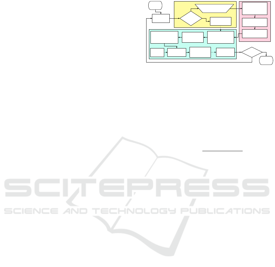
The details of the segmentation part of OOSfM are
shown in Fig. 2. OOSfM inputs images and ex-
tracts object hypotheses using the Geodesic Object
Proposals (GOP) method of Kr
¨
ahenb
¨
uhl and Koltun
(Kr
¨
ahenb
¨
uhl and Koltun, 2014). Then, the user is
prompted to scribble on the object of interest in only
the first image, and the initial segmentation is perfor-
med by choosing the GOP having the most similarity
and the least difference with the scribble in terms of
pixels spanned. The segmentation produced by object
proposals is coarse, with a high likelihood of several
object proposals covering different areas of the same
START
Load Img1,
Img2
Generate Mixture
Model 1 (MM1)
driven by OD
Select largest blob in
Img1 as object
Select Object
using blob
Segment Img2
using MM2
Choose blob with most
SIFT features matched
to those in blob of Img1
Scribble in Img1 on Object
Desired (OD)
Img1 = First
Image?
YES
NO
Last Image
pair?
STOP
Refine segmentation
of Img1 using MM1
Generate Mixture
Model 2 (MM2) driven
by Img1 segmentation
GOP on
Img2
Select largest
blob in Img2 as
object
Refine
segmentation on
Img2 using GOP
Use Object from
previous iteration
NO
YES
Figure 2: Detailed flowchart of the segmentation in
OOSfM.
object. Therefore, in order to better delineate the
boundaries of the sought-after object, an appearance-
based segmentation is implemented, using the appea-
rance of the selected object proposal to guide the pro-
cess.
The segmentation relies on the following Maxi-
mum A Posteriori (MAP):
p(c
l
|x
i
) =
p(x
i
|c
l
)p(c
l
)
∑
j
p(x
i
|c
j
)p(c
j
)
(1)
This formulation relies on a mixture model of the
image, where each pixel is generated by first choo-
sing the mixture component, or image segment, and
then generating the item from this component. The
prior probability p(pixel = c
l
), or simply p(c
l
), is the
probability of the pixel being generated from either
the object of interest or from background clutter. It
is calculated as p(c
l
) = n
l
/n, where n
l
is the number
of pixels belonging to cluster l, based on the object
proposal chosen before, and n is the total number of
pixels.
The likelihood p(x|c
l
) of generating a pixel with a
feature vector x, given a segment l, is computed using
the output of the GOP method. Here, we assume the
feature vector to be Gaussian with mean µ
l
and cova-
riance Σ
l
. It contains (1) the R,G, and B color values
at each pixel location; (2) the row (u) and height (v)
positions in the image; and (3) the local entropy para-
meters.
The new probabilities lead to an updated segmen-
tation for the first image. To ensure the object consists
of connected components and remove possible noisy
regions, we choose, as the final version of the object
of interest in the first image, the blob with the largest
number of connected pixels belonging to the object
cluster (see Fig. 3 to better clarify this step).
Once the different objects of interest are segmen-
ted in the first image, the segmentation can be pro-
pagated to the subsequent images, and is performed
according to a MAP, which is now conditioned on the
previous segmentation S
t−1
, in addition to the feature
Object Oriented Structure from Motion: Can a Scribble Help?
543
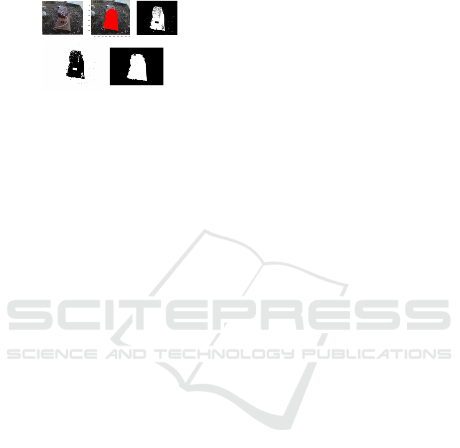
(a)
(c)(b)
(d) (e)
Figure 3: Sample segmentation results in OOSfM, (a) user
scribble, (b) selected GOP, (c) p(pixel label=object |x
l
), (d)
M.A.P. segmentation, (e) segmentation into connected regi-
ons (blobs) and selection of largest blob.
vector of the current frame. Blobs are extracted by re-
gion growing pixels labelled as objects. To match to
the selected blob in the first image, we choose, in the
new image, the blob containing the largest number of
SIFT features matched to those in the selected object
in the first image:
Blob
c,q
= argmax
i∈I
2
{| f (Blob
i
) ∩ f (Blob
q
)|;q ∈ I
1
}
(2)
where subscripts c and q are used to refer to the ‘cor-
responding’ and ‘query’ blobs respectively and f (.) is
the ensemble of features belonging to a blob. I
1
and I
2
refer to two different images in which blobs are being
matched, and |.| refers to the cardinality of the inter-
section.
The chosen blob is matched again to the closest
object proposal in image t, and the segmentation is fi-
nally refined by introducing a new mixture model and
MAP detector which are based, this time, on the last
segmentation of the image itself S
t
. The largest con-
nected area of pixels, labeled as object, is then finally
chosen as our object of interest.
3.2 Object Oriented Structure from
Motion
After the first step of OOSfM is complete and objects
are segmented in each image, we aim to extract the
structure and the motion by implementing a modified
version of SfM, which uses the objects’ segmentation.
Most steps are identical to those in the traditional SfM
pipeline, except for the bundle adjustment, as will be
explained below.
First, each pair of frames are considered sequenti-
ally, and SIFT features are detected and matched in
order to extract the Essential matrix relating image
pairs. Here, we assume each camera is already ca-
librated off-line. Then, a first estimate of rotation
and translation is obtained using least-squares (Hart-
ley and Zisserman, 2003). After that, the information
from successive frames is combined, while keeping
track of the common features. Each time a new image
is added, the 2D features are triangulated to their 3D
position using our first guess of camera rotations and
translations. After looping over all images, the com-
plete set of structure and motion parameters are then
optimized for, in the bundle adjustment step (Triggs
et al., 1999), using the first triangulation as an initial
guess for the Levenberg-Marquardt algorithm. The
structure and camera positions, which we optimize
for, are parameterized by a single state vector v. The
simplest formulation of the bundle adjustment step
aims to minimize the sum of the squared re-projection
errors of all the points in the scene, re-projected onto
all cameras in which they are observed:
min
v
∑
cam.
∑
3D pts.
(x − x
rep
(v))
2
+ (y − y
rep
(v))
2
, (3)
where, the measured row and column positions
of image features are represented by (x,y), while
the predicted values of these features are denoted
(x
rep
(v),y
rep
(v)).
Assuming the measurement noise is Gaussian, this
minimization gives the Maximum Likelihood (ML)
solution, which represents the jointly optimal struc-
ture of the scene and the motion parameters of the
cameras (Hartley and Zisserman, 2003).
In the formulation of (3), the terms inside the sum
are equally weighted, and as such, points belonging
to the objects and others belonging to the background
equally contribute to the optimization results. The fi-
nal re-projection error of the structure is in this case
minimized, such that it compromises the error attri-
butable to both the objects and background. For this
reason, we propose to introduce the change in the SfM
pipeline at the level of the bundle adjustment in a way
to give more weight to the object of interest, which in
general contains less noisy feature matching than the
background.
3.2.1 Minimizing the Object Error, with a
Bound on the Background Error
To minimize the negative effect of errors in back-
ground estimation on the accuracy of the estimated
structure of objects, the first method we propose is to
reformulate the bundle adjustment step as a constrai-
ned optimization problem, where the new objective
function aims to minimize the sum of squared re-
projection errors of points exclusively belonging to
the selected objects of interest, rather than the entire
scene. In the optimization, we bound the background
re-projection error and include it as a hard constraint.
The upper bound for the background re-projection er-
ror is denoted by threshold n. The optimization is ex-
VISAPP 2018 - International Conference on Computer Vision Theory and Applications
544

pressed mathematically as follows:
min
v
∑
cam.
∑
3D pts.∈obj
(x − x
rep
(v))
2
+ (y − y
rep
(v))
2
subject to:
∑
cam.
∑
3D pts.∈back
(x − x
rep
(v))
2
+ (y − y
rep
(v))
2
≤ n
(4)
The value chosen for n greatly affects the results of
the optimization. In order to improve on the object
re-projection error resulting from the vanilla version
of SfM in (3), n should be larger than the background
error resulting from the normal bundle adjustment,
where all points are considered uniformly. Therefore,
the minimum value of n is estimated by running nor-
mal SfM.
3.2.2 Object-Only SfM
In the previously described method, we formulate BA
as a constrained optimization and solve for all para-
meters at once. However, the background constraint
does not only involve the background structure points.
It also influences the camera positions, and thus it
might be negatively affecting the object structure pa-
rameters despite the decrease in the total object re-
projection error. For this reason, we try to investigate
the effect of background points on the optimization.
The next BA variant eliminates completely the
background points from the objective function (Eq.
5). It minimizes the total re-projection error of object
points, without any consideration to the background
points, which are kept however part of the optimiza-
tion parameters for comparison purposes.
min
v
∑
cam.
∑
3D pts.∈obj
(x − x
rep
(v))
2
+ (y − y
rep
(v))
2
(5)
3.2.3 Weighted Bundle Adjustment
Removing background points completely from the
cost function of the optimization could have nega-
tive effects on the output structure of the object. In
fact, as it will be shown in the results section, more
points in the optimization usually lead to a better re-
construction. For this reason, the next formulation
keeps the background points as part of the objective
function, but with a lower weight. Note that this idea
is similar in spirit to the covariance-weighted bundle
adjustment formulation (Triggs et al., 1999).
min
v
∑
cam.
∑
3D pts.∈obj
(x − x
rep
(v))
2
+ (y − y
rep
(v))
2
+
∑
cam.
∑
3D pts.∈back.
λ(x − x
rep
(v))
2
+ (y − y
rep
(v))
2
(6)
λ is a weight factor (less than 1), whose role is to de-
crease the effect of the background on the results. By
keeping the background points inside the optimiza-
tion, we avoid overfitting the camera parameters to
the object of interest.
4 EXPERIMENTS AND RESULTS
The different OOSfM versions were tested on a num-
ber of publicly available real and synthetic datasets,
consisting of multi-view images of different scenes,
each with a different number of images of different
resolutions. Since OOSfM is designed to reconstruct
objects and not large-scale scenes, we observe that a
relatively small number of images is sufficient to eva-
luate its performance. Although our SfM variants can
be bootstrapped off of any SfM implementation, we
choose to build off the implementation of SFMedu
(Xiao, 2014). For the constrained bundle adjustment
step, a first-order interior-point algorithm was used
with an appropriate function tolerance. Sequential
quadratic programming was also used on some da-
tasets where convergence was not met through the
interior-point method.
4.1 Results on the Segmentation Part of
OOSfM
The first part of our SfM formulation involves the seg-
mentation of the object of interest, starting with the
user scribble on the first image.
Fig. 4, 5 and 6 present the results of the interactive
segmentation, and the propagation of the segmenta-
tion across images of the Clocktower (Kowdle et al.,
2010), Stone (Kowdle et al., 2010) and fountain-P11
(Strecha et al., 2008) datasets. The algorithm does
well even on difficult datasets like Stone. For Clock-
tower, the segmentation is still capable of detecting
the tower in spite of it being severely occluded by a
tree in many of the frames.
4.2 Performance of OOSfM
After the segmentation, the remaining components
of OOSfM, with the different modified versions of
BA, are applied to every dataset, focusing the recon-
struction on a specific object with a random shape in
the scene. The first metric that we use to evaluate the
three variants we present is the average re-projection
error, which is defined as (2
q
∑
residuals
2
|residuals|
), for the ob-
ject points alone since our aim is to test the effect of
OOSfM on the object structure.
Object Oriented Structure from Motion: Can a Scribble Help?
545
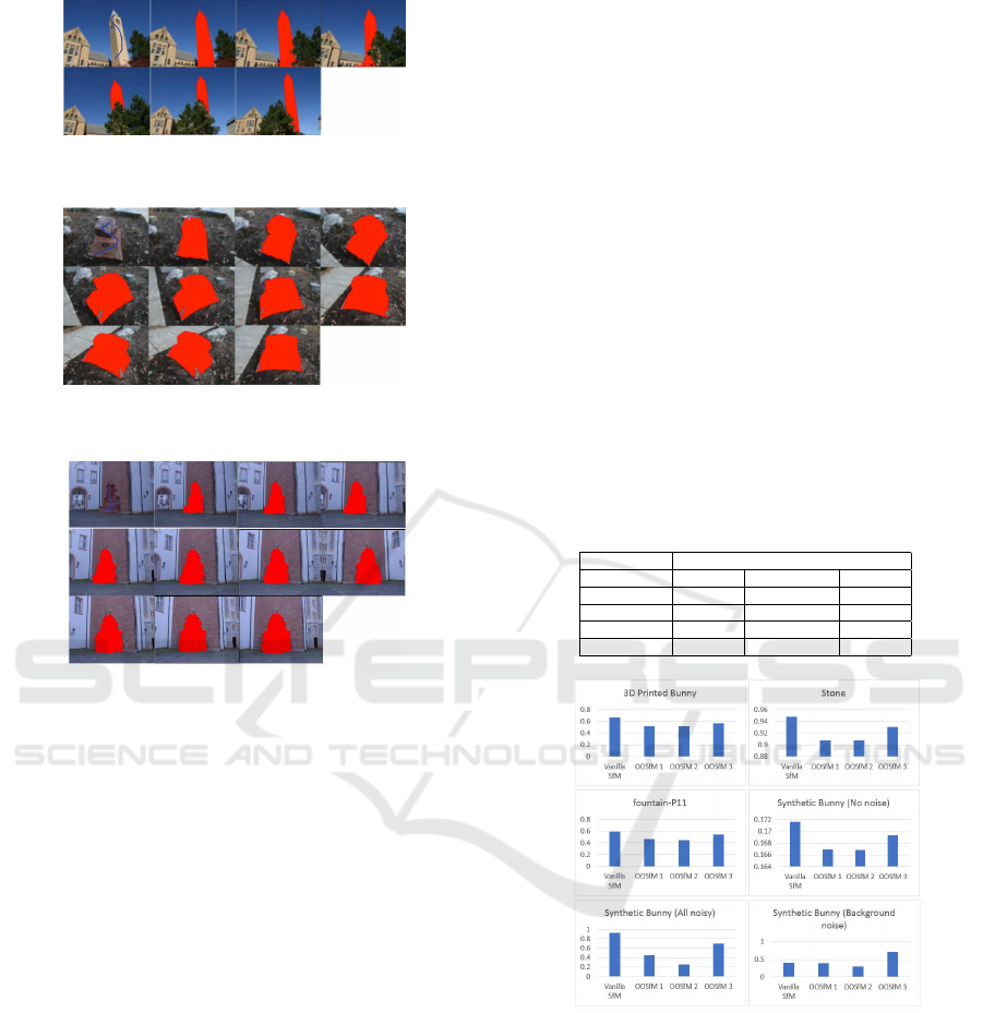
Figure 4: Results on the Clocktower dataset; images are
ordered from left to right on each row.
Figure 5: Results on the Stone dataset; images are ordered
from left to right on each row.
Figure 6: Results on the fountain-P11 dataset; images are
ordered from left to right on each row.
We choose real datasets with a rich number of fe-
atures to test our algorithms: ”3D Printed Bunny”,
”Stone” and ”fountain-P11”, where the interactive
segmentation has been successful to delimit the ob-
ject of interest in the scene. SIFT features are used
to perform the matching at the level of these datasets.
A synthetic dataset, ”Synthetic Bunny”, is also crea-
ted with the Stanford Bunny (Turk and Levoy, 2005)
as the object of interest. Ray tracing from the ground
truth point cloud is used in this case to recover the 2D
features, to eliminate the errors that could be induced
by the SIFT matching.
Artificial noise is added to the 2D matched points
of the ”Synthetic Bunny” dataset, to end up with three
scenarios: ”Synthetic Bunny (No noise)”, with no
added noise to the matches. The SfM result in this
case is already good (average total re-projection error
of 0.177653). ”Synthetic Bunny (All noisy)”, where
noise is added on the re-projections of 1 in 5 points
of both object and background points. ”Synthetic
Bunny (Background noise)”, with added noise on the
re-projections of the background points to account for
the variability in the background.
The different variants of BA will be numbered as
follows in the rest of the paper:
1. Minimizing the Object Error, with a Bound on the
Background Error
2. Object-Only SfM
3. Weighted Bundle Adjustment (with a chosen
background weight λ = 0.5)
The re-projection errors for the ”3D Printed
Bunny” are first reported in details in Table 1. Fig.
7 then summarizes, for all the datasets, the change
in the re-projection error of the object alone as for-
mulations 1-3 are applied. For method 1, we set the
parameter n in the constraint to the background error
resulting from the vanilla SfM, added by 1 then roun-
ded to the nearest half-integer. The initial guess for
the optimization is the output of vanilla SfM for met-
hods 1 and 2, as for method 3, it is the triangulation
result.
Table 1: Average re-projection errors for the object, back-
ground, and total scene using the vanilla SfM and OOSfM
on the 3D printed Bunny dataset.
Re-projection Error
SfM variant Object Background Total
Vanilla SfM 0.659979 1.955798 1.299734
OOSfM 1 0.51802 2.941184 1.835419
OOSfM 2 0.51802 5.832184 3.570761
OOSfM 3 0.567647 2.043443 1.321943
Figure 7: Graphical comparison of the re-projection errors
of the object for both regular SfM and OOSfM (1-3). Note
the obvious drop in error for OOSfM variants on all datasets
except the last.
The first observation that we can make is that the
object re-projection error decreases compared to the
vanilla SfM output, as a result of all three BA modi-
fications, for all datasets except the last. In addition,
optimizing the cost function over the object alone wit-
hout any consideration to the background always gi-
ves the lowest object re-projection error. This ideally
should mean a better reconstruction for the object of
interest. Therefore, based on the re-projection error
VISAPP 2018 - International Conference on Computer Vision Theory and Applications
546
metric alone, the result of the BA optimization on the
object is best when the object is taken alone (met-
hod 2). Since our original aim was to keep the object
within context by maintaining an acceptable estimate
of the background, it seems that methods 1 and 3 give
the results that we are looking for.
However, the re-projection residual alone is not
a good indicator of the quality of the reconstruction.
For instance, in (Ma et al., 2015), a better cylindri-
cal structure was actually at the cost of an increase in
the re-projection error of the scene. In our formula-
tion, constraining the bundle adjustment step to ob-
ject points only could lead to overfitting the camera
parameters to the object of interest. This can be in-
ferred from the high re-projection error that results on
the background points compared to vanilla SfM, for
the same 3D points positions. The idea is similar in
concept to the case of fitting a line to points, where fe-
wer points could lead to an erroneous representation
of the global picture. It is also hard to visually assess
whether any method is performing better than the ot-
her in terms of improving the object’s structure (Fig.
8).
Figure 8: Point clouds of the fountain-P11 object, using the
different SfM methods: Vanilla SfM result of the fountain
(object) overlaid on the ground truth point cloud of the en-
tire scene (top left), OOSfM 1 (top right), OOSfM 2 (bottom
left) and OOSfM 3 (bottom right) results of the object.
A comparison to ground truth data is therefore
performed to assess the different methods presented,
and to find out whether it is indeed possible to im-
prove the reconstruction of the object of interest. This
is done on the first scenario of the ”Synthetic Bunny”
dataset, without any added noise. For the compari-
son, the object of interest is segmented from the out-
put point cloud that each OOSfM generates, as well
as, from the ground truth point cloud. The two object
point clouds are manually aligned using three anchor
points, while allowing for optimization of scale, rota-
tion, and translation between them. The iterative clo-
sest point (ICP) (Besl and McKay, 1992) algorithm is
then applied to minimize the root mean square error.
This error is reported for each method in Table 2.
Table 2: Comparison of the RMS error with the ground truth
object using the vanilla SfM and OOSfM for the Synthetic
Bunny (No noise) dataset.
Synthetic Bunny (No noise)
RMS error
Vanilla SfM 0.0144957
OOSFM 1 0.0186764
OOSfM 2 0.0194392
OOSfM 3 0.0147708
While the RMS error is small for all methods , the
vanilla SfM result still shows the lowest error with the
ground truth point cloud of the object. The object-
only result (OOSfM 2) shows the highest RMS er-
ror; it is explained by the fact that the camera para-
meters obtained from the optimization are overfitting
the object. This in turns causes the object’s points in
3D to move, leading to a worse object point cloud in
spite of the lower re-projection error. In OOSfM 1
as well, allowing for a higher error in the background
while decreasing the object’s error does not guarantee
a better structure. On the other hand, keeping back-
ground points in the optimization, even with a lower
weight (OOSfM 3), gives an RMS error very close to
the vanilla result. This brings us to the conclusion that
keeping background points as part of the optimization
improves the final reconstruction of the object.
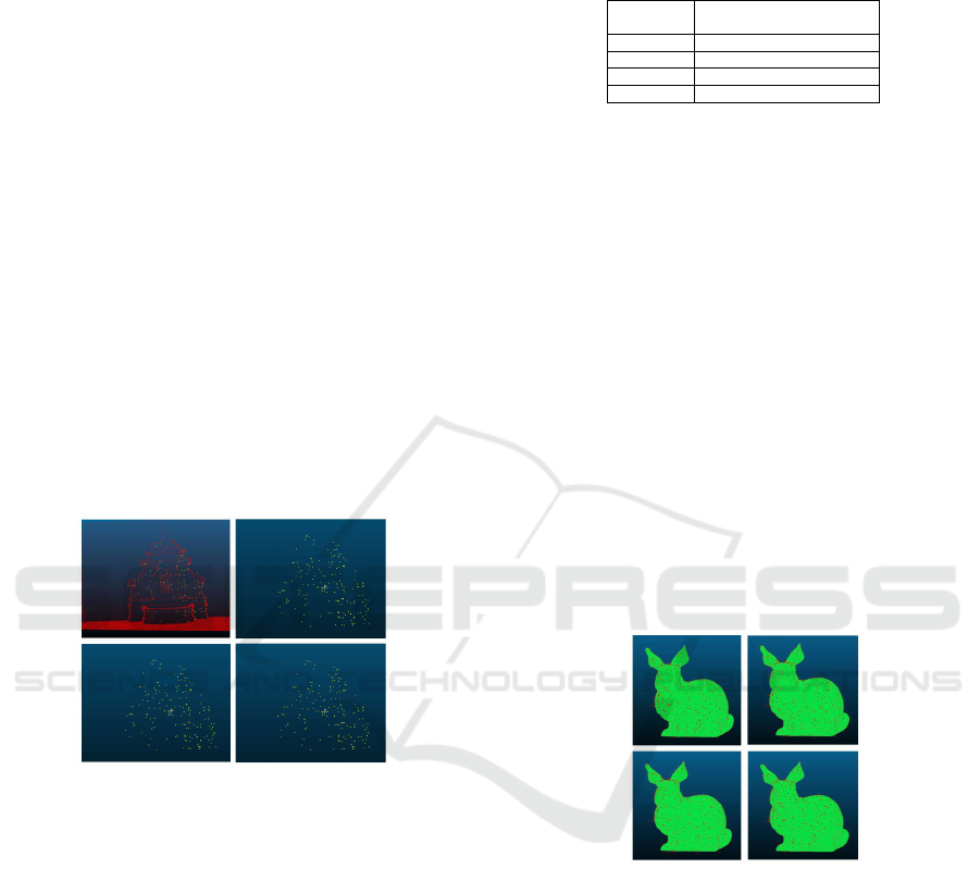
Figure 9 shows the 3D points found through va-
nilla SfM and each variant of OOSfM, overlaid on the
Stanford Bunny from the synthetic dataset.
Figure 9: Results showing the Stanford bunny from the
synthetic dataset with the overlay of 3D points resulting
from vanilla SfM (top left), OOSfM 1 (top right), OOSfM 2
(bottom left), and OOSfM 3 (bottom right). Here the change
is more prominent; note how point clouds using vanilla SfM
and OOSfM 3 (weighted BA) fit the model better, because
they take background points into consideration.
5 CONCLUSIONS
We introduced a system that automatically tracks ob-
jects through a sequence of images, based on an initial
user scribble. We then tested different bundle adjust-
ment formulations that attempted to give more weight
on the object of interest. While we decreased the to-
tal object re-projection error using the three BA vari-
Object Oriented Structure from Motion: Can a Scribble Help?
547

ants, we demonstrated that vanilla SfM outperforms
the other formulations in terms of accuracy of the re-
constructed objects. The main conclusion that we can
make is that a lower re-projection error does not ne-
cessarily correspond to a better structure, which puts
into question the accuracy of this metric as a measure
of the structure estimate when dealing with specific
objects, rather than the entire scene. In the future,
we will study the effect of semantics on the recon-
struction of the object of interest, and whether additi-
onal prior information about the nature of the object
could improve on the vanilla result of the SfM pro-
blem.
ACKNOWLEDGEMENTS
This work was supported by the Lebanese National
Council for Scientific Research (LNCSR).
REFERENCES
Bao, S. Y., Bagra, M., Chao, Y. W., and Savarese, S. (2012).
Semantic structure from motion with points, regions,
and objects. In IEEE Conference on Computer Vision
and Pattern Recognition (CVPR), pages 2703–2710.
Besl, P. J. and McKay, N. D. (1992). A method for regis-
tration of 3-d shapes. IEEE Transactions on Pattern
Analysis and Machine Intelligence, 14(2):239–256.
Cipolla, R. and Robertson, D. (1999). 3d models of ar-
chitectural scenes from uncalibrated images and va-
nishing points. In Image Analysis and Processing,
1999. Proceedings. International Conference on, pa-
ges 824–829.
Crocco, M., Rubino, C., and Del Bue, A. (2016). Struc-
ture from motion with objects. In IEEE Conference
on Computer Vision and Pattern Recognition (CVPR).
Debevec, P. E., Taylor, C. J., and Malik, J. (1996). Mo-
deling and rendering architecture from photographs:
A hybrid geometry-and image-based approach. In
Annual conference on Computer graphics and inte-
ractive techniques, pages 11–20.
Fioraio, N. and Di Stefano, L. (2013). Joint detection,
tracking and mapping by semantic bundle adjustment.
In IEEE Conference on Computer Vision and Pattern
Recognition (CVPR), pages 1538–1545.
Frahm, J. M., Fite-Georgel, P., Gallup, D., Johnson, T., Ra-
guram, R., Wu, C., and Pollefeys, M. (2010). Building
rome on a cloudless day. In European Conference on
Computer Vision (ECCV), pages 368–381.
Frost, D. P. and Murray, D. W. (2016). Object-aware bundle
adjustment for correcting monocular scale drift. In
IEEE International Conference on Robotics and Au-
tomation (ICRA), pages 4770–4776.
G
´
alvez-L
´
opez, D., Salas, M., Tard
´
os, J. D., and Montiel,
J. M. M. (2016). Real-time monocular object slam.
Robotics and Autonomous Systems, 75.
Hartley, R. and Zisserman, A. (2003). Multiple view geome-
try in computer vision. Cambridge University Press.
Kowdle, A., Batra, D., Chen, W. C., and Chen, T. (2010).
imodel: interactive co-segmentation for object of in-
terest 3d modeling. In European Conference on Com-
puter Vision (ECCV), pages 211–224.
Kr
¨
ahenb
¨
uhl, P. and Koltun, V. (2014). Geodesic object pro-
posals. In European Conference on Computer Vision,
pages 725–739.
Ma, T., Sun, Z., Zhang, W., and Chen, Q. (2015). Three-
dimensional reconstruction of a cylinder surface based
on constrained bundle adjustment. Optical Engineer-
ing, 54(6):063101–063101.
Oh, B. M., Chen, M., Dorsey, J., and Durand, F. (2001).
Image-based modeling and photo editing. In Annual
conference on Computer graphics and interactive
techniques, pages 433–442.
Sch
¨
onberger, J. L. and Frahm, J. M. (2016). Structure-from-
motion revisited. In IEEE Conference on Computer
Vision and Pattern Recognition (CVPR).
Sinha, S. N., Steedly, D., Szeliski, R., Agrawala, M., and
Pollefeys, M. (2008). Interactive 3d architectural mo-
deling from unordered photo collections. ACM Tran-
sactions on Graphics, 27(5):159.
Strecha, C., Von Hansen, W., Van Gool, L., Fua, P., and
Thoennessen, U. (2008). On benchmarking camera
calibration and multi-view stereo for high resolution
imagery. In Computer Vision and Pattern Recognition,
2008. CVPR 2008. IEEE Conference on, pages 1–8.
Ieee.
S
¨
underhauf, N., Dayoub, F., McMahon, S., Eich, M., Up-
croft, B., and Milford, M. (2015). Slam–quo vadis?
in support of object oriented and semantic slam. In
Robotics and Systems (RSS) Workshop, Rome, Italy.
Triggs, B., McLauchlan, P. F., Hartley, R. I., and Fitzgibbon,
A. W. (1999). Bundle adjustment—a modern synthe-
sis. In Hieidelberg, S. B., editor, International works-
hop on vision algorithms., pages 298–372.
Turk, G. and Levoy, M. (2005). The stanford bunny.
Van den Hengel, A., Dick, A., Thorm
¨
ahlen, T., Ward, B.,
and Torr, P. H. (2007). Videotrace: rapid interactive
scene modelling from video. ACM Transactions on
Graphics (ToG), 26(3):86.
Xiao, J. (2014). Sfmedu. http://vision.princeton.edu/
courses/SFMedu/.
Zhu, H., Meng, F., Cai, J., and Lu, S. (2016). Beyond pixels:
A comprehensive survey from bottom-up to seman-
tic image segmentation and cosegmentation. Journal
of Visual Communication and Image Representation,
34:12–27.
VISAPP 2018 - International Conference on Computer Vision Theory and Applications
548
