Active Haptic Control for a Biologically Inspired Gripper in
Reconfigurable Assembly Systems
Testing Active Haptic Control through Force Feedback
Christian Ivan Basson and Glen Bright
Discipline of Mechanical Engineering, University of KwaZulu-Natal, King George V Ave, Durban, South Africa
Keywords: Flexibility, Shape Conformity, Adaptability, Active Haptic Control, Force Feedback.
Abstract: Haptic feedback for flexible grippers enhances control over human-machine interaction and object
manipulation. Force feedback control through a haptic sensory system enables gripping sensitivity for the
grasping of fragile components. The development of intelligent gripping systems has the potential to be
implemented in Reconfigurable Assembly Systems, (RAS), for on-demand production lines. Advancements
in object control and successful object handling for assembling systems were investigated. An active haptic
control system was developed to assess the adaptability of gripper appendage grip force through a dynamic
pick and place movement. The aim was to determine the force output from a self-adjusting grasping procedure
using a haptic feedback control sensory system. The force output data was empirically collected and plotted
on a signal verse time graph. The voltage signal representing the actual grasp force throughout a gripping
procedure. The testing was performed on a previously manufactured gripper based on a biologically inspired
phenomenon called the Fin Ray Effect
®
. Conclusions and recommendations were made in relation to effective
grip force control.
1 INTRODUCTION
Modern assembly systems require superior production
rate capabilities. Reconfigurable Manufacturing
Systems, (RMS), satisfies the requirements for
flexibility and reconfigurability in manufacturing.
Production lines are required to be efficient in terms of
precise part control and placement (Bouchard, 2014).
Reconfigurable Assembly Systems, (RAS) are defined
by (Koren and Shpitalni, 2010) as follows:
“Reconfigurable assembly systems are those that can
rapidly change their capacity (quantities assembled)
and functionality (product type, within a product
family) to adapt to market demand”.
Flexible fixtures in RAS cater for product variety
and changes in part size through adjustable
mechanisms in dynamic response environments for
on-demand production (Padayachee and Bright,
2013). Flexible grippers are therefore applicable in
RAS. The end-effector of a robotic manipulator is
essential for part handling (Reddy and Suresh, 2013).
Flexible grippers are developed for multi-function
and high flexibility in gasping operations for pick and
place procedures and fixturing applications.
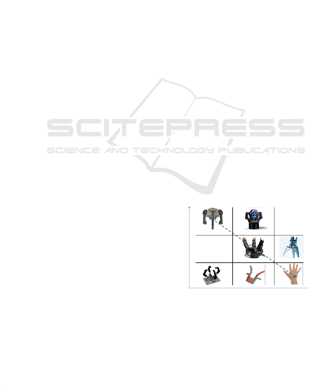
Grippers are improved through the means of
flexibility and performance. Flexibility and
performance have an inverse relationship with a one-
another shown in Figure 1. Gripper systems with high
flexibility sacrifice performance and vice-versa.
Grippers possessing adaption to part variety require
haptic feedback to increase the performance of
gripping.
Flexibilit
y
Performance
Number of tasks it can do
Accuracy and
repeatability
Figure 1: Performance verse flexibility of grippers.
Basson, C. and Bright, G.
Active Haptic Control for a Biologically Inspired Gripper in Reconfigurable Assembly Systems - Testing Active Haptic Control through Force Feedback.
DOI: 10.5220/0006840800810090
In Proceedings of the 15th International Conference on Informatics in Control, Automation and Robotics (ICINCO 2018) - Volume 2, pages 81-90
ISBN: 978-989-758-321-6
Copyright © 2018 by SCITEPRESS – Science and Technology Publications, Lda. All rights reserved
81

Product assembly in manufacturing is ineffective
in human-computer integration because assembly
systems consist mainly of geometric constraints and
lack haptic feedback attributes (Xia, 2016). Haptic
systems are divided into three (3) focus areas: Human
haptics, computer haptics and machine haptics.
Human haptics concern the sense of touch between a
human and object. The human “intuition” is described
as the input to a machine for object manipulation. The
algorithms and software utilized in computational and
simulated haptic feedback to describe the properties
of the interacted object are termed computer haptics.
Machine haptic technology is the focus research
of this paper. Machine haptics refers to the haptic
touch interfaces between a machine and an object.
The development and design of the haptic devices
augment and simulate human touch for intelligent
gripping systems.
Part handling employing haptic force sensitive
systems enable the complete control without human
intervention. Surface damage during part grasping is
avoided by utilizing minimum force threshold values.
Slippages are reduced through force control. Haptic
feedback systems allow for enhanced part machine
interactions. Haptic feedback systems can be
classified as active and passive.
Passive haptic feedback systems are implemented
into the monitoring of gipping systems without
energy inputs into the actuation of the grippers.
Active haptic feedbacks systems possess either partial
or full control of force application of gripping device
onto the object or computer-generated simulations
(Martin, et al., 2013). An active haptic feedback
system was investigated and introduced in the design
of a force-feedback control system. The active force
feedback additionally enables monitoring of force.
Active haptic control is necessary for orientation
and input acknowledgement. Haptic systems provide
improved mobility for robots in the form of touch
sense. Haptic control minimizes human interaction in
complex machine mechanisms and movement.
Physiological presence is improved through the
means of enhancing machines with intelligent control
systems using touch.
2 FLEXIBLE GRIPPERS IN
LITERATURE
Flexible grippers and fixtures are investigated to
substitute dedicated assembly stations that are
composed of devoted grasping and fixturing
mechanisms. The reduction of time loss per station
change in an assembly or disassembly of components
decreases overall production time. Modular and/or
flexible gripping methods have been recognized to
minimize time consumption in assembly station
overlay (Molfino, et al., 1999).
A six (6) degree of freedom design of a gripping
system for Flexible Fixtureless Assembly, (FFA), was
developed by (Yeung and Mills, 2004). The gripper
system designed provides functions for both a conven-
tional fixture and reconfigure-able gripper. The gripper
is able to change the gripping configurations to suit the
assembly procedure and part variety. A drawback to
the system was the position of grasp points on the
object to be manipulated has to be known. The
flexibility in terms of self-adjustment can potentially
be compromised.
A reconfigurable gripper design was investigated
by (Molfino, et al., 2006), using modular fixture units
to assemble and disassemble a washing machine. The
gripper mechanism consisted of rigid links and
hinges. The modular fixture device incorporates a
fuzzy controller to implement force control to identify
extrusions on the part surface. An anthropomorphic
modular reconfigurable gripper purposed by (Staretu,
2015), using exchangeable finger orientations. The
modularity of gripper appendages increases grip
variation for size and shape of objects.
A gripping mechanism consisting of Fin Ray
Effect
®
based appendages are described by (Tharayil,
et al., 2017). Self-conformity was investigated in the
Fin Ray structure and implemented in a self-
adjustment gripper system. The Fin Ray Effect
®
is
described by the deformation of a V-shaped rib
structure through an applied force P (Pfaff, et al.,
2011), illustrated in Figure 2. The undeformed rib
structure is shown in A and the deformed rib structure
is shown in B.
Figure 2: The working principle of the Fish Fin Effect
®
(Pfaff, et al., 2011).
Potential flexible grippers can be categorised as:
multi-fingered grippers, enveloping grippers and
malleable grippers. The design criteria comparison is
shown in Tables 1, 2 and 3, according to the
advantages, disadvantages and significant application.
ICINCO 2018 - 15th International Conference on Informatics in Control, Automation and Robotics
82
A design should be suitable for an applicable gripping
function.
Table 1: Advantages of flexible grippers.
Design Advantages
Multi-fingered
grippers
Flexibility gripping for different object
shapes, gripping wit force feedback
Enveloping
grippers
Adaptability to mould around the
object
Malleable
grippers
Adaptable to different shapes, reliable
gripping
Table 2: Drawbacks of flexible grippers.
Design Drawbacks
Multi-fingered
grippers
Control complexity
Enveloping
grippers
Low force control capability
Malleable
grippers
Low gripping dexterity
Table 3: Significant application of flexible grippers.
Design Significant Application
Multi-fingered
grippers
Grasping all shaped objects with force
control
Enveloping
grippers
Grasping oddly shaped and unknown
objects
Malleable
grippers
Grasping unknown and specially
deformed objects
3 HAPTIC CONTROL FOR
GRIPPERS IN LITERATURE
Haptic feedback is utilized in gripper systems enabling
force feedback control. The grasping sensitivity is
attained through haptic feedback. Force management
reduces the unintended damage of handled part and
gripper mechanisms. The force control decreases the
probability of unwanted slippage and increases self-
adjustability.
A force feedback control system through a
miniature load cell for a rigid 3d-printed 2-finger
gripper is proposed by (Lipina, et al., 2011). Object
manipulation was required in the circumstance of a
power failure during the extension of a robot arm. The
force of the gripper was influenced through the
changing the input current (Ampere) and the force was
measured through a miniature load cell.
A haptic control system utilizing Shape Memory
Alloys, (SMA) as a gripper actuator, is presented by
(Yan, et al., 2012). The haptic control is performed by
means of potential difference (Voltage) across micro-
deformations from Polyvinylidene Fluoride Films
PVDF), due to their piezoelectric properties. The
PVDF sensors are embedded as tactile sensors.
A tele-manipulation (master-slave operation) for a
gripper system was presented by (Park, et al., 2016) to
replace human presence at task site. The telepresence
extends human touch to the environment remotely. The
haptic sense interface utilizes Force Sensitive Resistors
(FSR) and laser distance sensors inserted in the slave
device (the gripper). The master device (remote
controller) manipulates the force feedback by means of
magnetorheological (MR) glove acting as force-
control, increasing and decreasing force commands.
4 PREVIOUS DESIGN OF
A 4-FINGER GRIPPER
4.1 Mechanical Design of Gripper
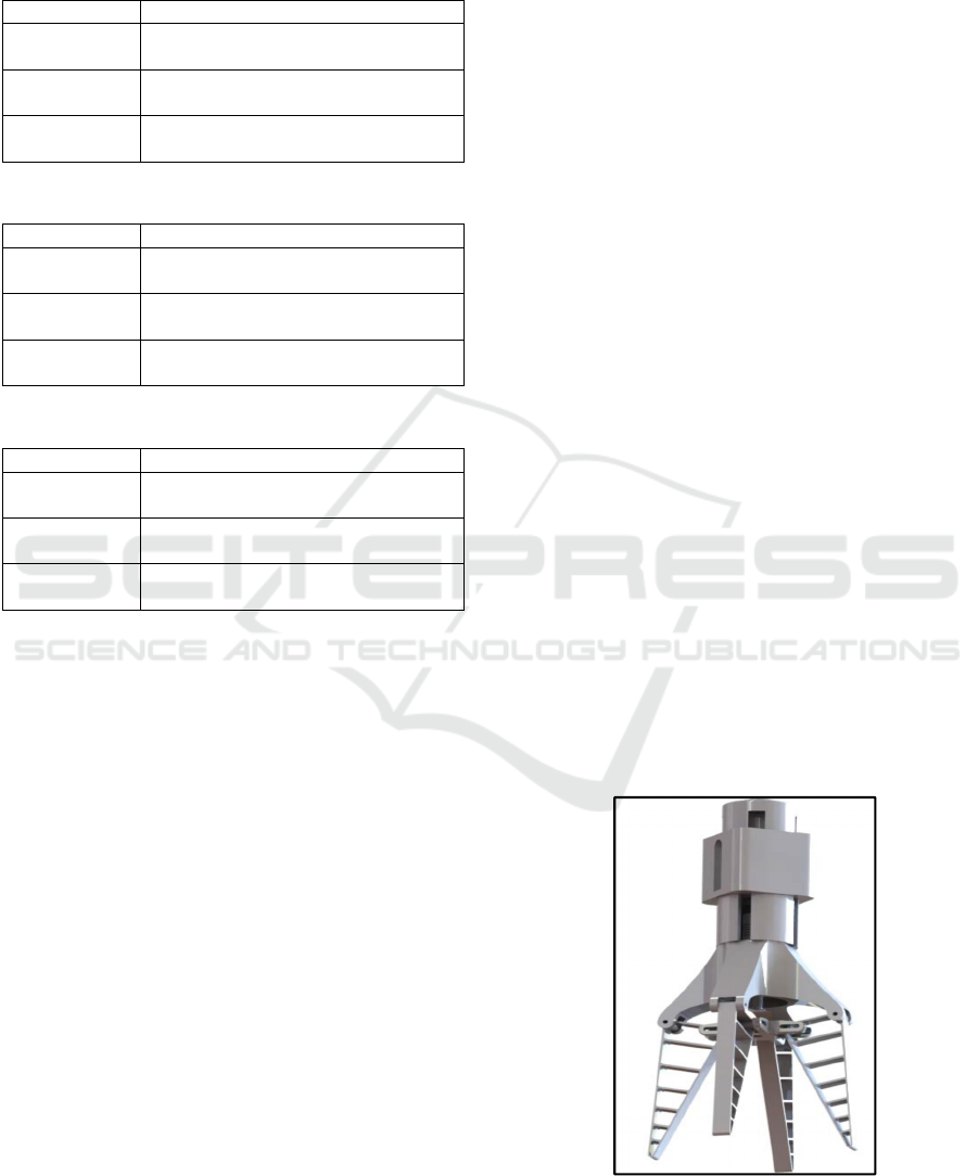
The study was conducted on a previously designed
Fin Ray Effect
®
based gripper that was developed by
(Basson, et al., 2017). The 4-finger gripper was
designed and based on the Fin Ray Effect
®
, shown in
Figure 3. The design was inspired by the FESTO
®
Multi Choice Gripper (FESTO, 2014). The gripper
appendage design was based on conformity studies
investigated in the design of the TIHRA gripper
(Crooks, et al., 2016).
The design was manufactured from Acrylonitrile
Butadiene Styrene, (ABS), plastic and by means of
3D printing. The mechanical properties of ABS allow
for flexibility and strength to sustain deformation
without failure. The Elastic Modulus (E) of ABS
plastic is 2 GPa, the Poisson’s Ratio (υ) is 0.4 and the
Yield Stress (σ
y
) is 45 MPa.
Figure 3: 4-Finger proposed gripper design (Basson, et al.,
2017).
Active Haptic Control for a Biologically Inspired Gripper in Reconfigurable Assembly Systems - Testing Active Haptic Control through
Force Feedback
83
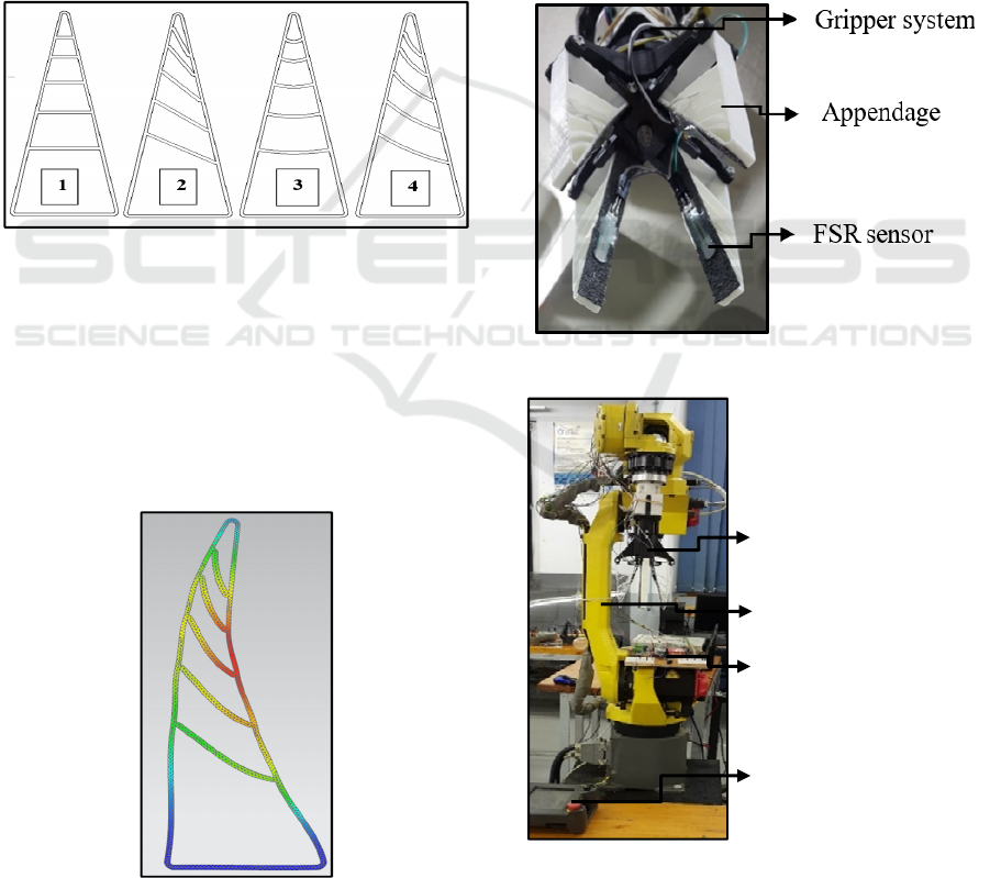
4.2 Design and Simulation of the
Selected Appendage
The rib design for the appendage was selected from
four (4) geometries and was described by (Basson, et
al., 2017), shown in Figure 4. Geometry 1 utilized the
traditional Fin Ray Effect
®
concept with parallel ribs.
Geometry 2 was designed with a slanted rib structure.
Geometry 3 comprised of concentric curved ribs.
Geometry 4 possessed the rib structures of Geometry
3 and Geometry having curved and slop structures. A
Finite Element Analysis, (FEA), was performed on
the various rib structures and the conformity was
examined in relation to the Fin Ray Effect
®
. The
design appendages demonstrated self-conformity
with respect to rib deflection.
Figure 4: Rib structure design for appendages (Basson, et
al., 2017).
A non-linear static analysis was performed and
Geometry 4 was found to be the best-suited rib
structure, illustrated in Figure 5. A force of 10 N was
applied against the gripping face of the appendage.
The stress and deflection results from the simulation
yielded 19.84 MPa and 2.28 mm respectively. The
deflection was 29.3% larger than that of Geometry 1.
Figure 5: Deflection shape of Geometry 4 (Basson, et al.,
2017).
4.3 Gripper and Robotic Arm
Integration
The gripper system was installed onto the end-
effector attachment of a FANUC M-10iA robotic
arm. The gripper system consisted of the actuated
gripper and the force feedback sensory system. The
actuator employed was a NEMA 17 stepper motor
and was connected to stepper motor controller. Force
Sensitive Resistors, (FSR), were utilised as haptic
feedback for the gripper, shown in Figure 6. The
stepper motor controller and the sensors were linked
to an Arduino Mega 2560 microcontroller. The
gripper system was connected through a wire system
to the respective electronic components illustrated in
Figure 7.
Figure 6: Installed sensory system.
Figure 7: Frontal view of robot gripper and gripper system.
R
o
b
ot teac
h
Pendant
C
ontro
l
Board
A
ttac
h
e
d
Gripper
R
o
b
ot
i
c arm
ICINCO 2018 - 15th International Conference on Informatics in Control, Automation and Robotics
84
The solution was proposed as an alternative for
traditional grippers. Flexibility is increased by selecting and
designing appendages to mimic human-like fingers in a
grasping motion. The intention of the design was to test and
manufacture a lightweight and flexible gripper for the ease
of instalment. The haptic system was implemented for
operational environments where product structural integrity
through handling would not be compromised. The gripper
actuation method using motor actuation was changed in
comparison to FESTO’s MultiChoiceGripper
®
, which used
pneumatic actuation. The rib structure was modified
therefore improving grasping properties from the traditional
rib design.
5 ACTIVE HAPTIC CONTROL
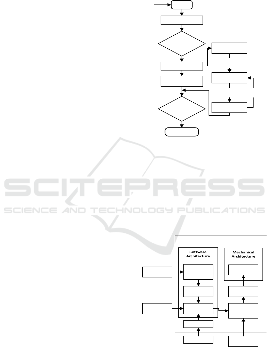
5.1 Pseudocode and Flow Diagram for
the Mechatronic Control
The pseudocode described the procedural layout of
the mounted gripper system and included haptic
control, shown in Figure 8. The program was initiated
and started the operation procedure. The system
located the grasping location of the object by means
of a written input code. The object was grasped with
aid of push-button control, which resembled a written
code that initiated the closing of appendages to grasp
the object. The system was verified for an accepted
grasp. The system reinitiated the grasping procedure
when the grasp was unacceptable.
Acceptable grasps resumed enclosing the gripper
appendage and exceeded a lower force threshold (A).
The lower force threshold initiated automatic closing
of the gripper until a high force threshold (B) was
attained. The gripper was programmed to open
automatically until a force threshold (C) was met. The
force threshold (C) value was located at a fraction
value below threshold (B). The variation between (B)
and (C) existed for self-adjustment just below the
force magnitude required to damage the grasped
object. The grip intensity self-regulated when
unintended grip force interferes were present in the
required force grip when experiencing dynamic
motion.
The program identified the release location. A
push button or over-riding code was programmed to
disengage self-regulating loop for the release of the
object. The program ended and started a new
operation cycle.
START
Locate Object
Grasp Object
Locate Release
Location
Push Button
For Releasing
RETURN
Low Force
Threshold (A)
High Force
Threshold (B)
Push Button
For Grasping
Force
Threshold (C)
Gripper
opening
Gripper
closing
Gripper
closing
Figure 8: Operational pseudocode for the gripping system.
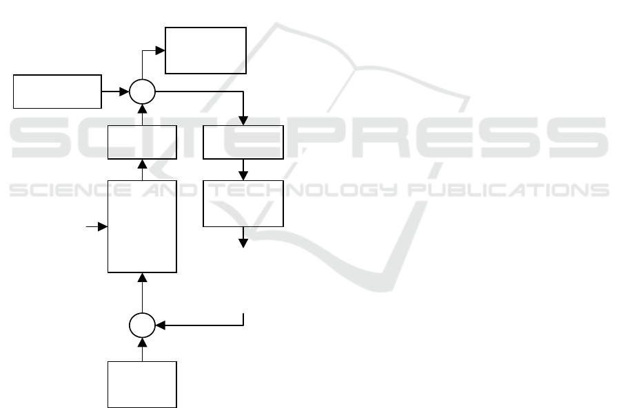
The mechatronic system architecture of the
gripper system consisted of a software architecture
and a mechanical architecture, shown in Figure 9. The
gripping sequence was initiated by means of push-
button input through human involvement. The haptic
input signal from the FSR sensors was converted and
relayed to the system controller. The system
controller transmitted the signal to the stepper motor
controller and manipulated the stepper motor. The
manipulation of the actuation influenced the grip
movement direction on the gripper.
Figure 9: Logic flow diagram of haptic gripper system
architecture.
FSR Sensory
Input
Force
Threshold
Detectio n
Force Signal
Conversion
System
Contro ller
Push Buttons
Human Input
5 V Power
Supply
Stepper
Motor
Contro ller
24 V Power
Supply
Stepper
Motor
Fin Ray
Gripper
Mechatronic Archite cture
Active Haptic Control for a Biologically Inspired Gripper in Reconfigurable Assembly Systems - Testing Active Haptic Control through
Force Feedback
85
5.2 Force Feedback Control Loop
The force feedback control loop is illustrated for the
haptic control of the gripper system. Initial force input
is recorded through a push-button resembling an input
voltage. The threshold values are the required values
for the control system to regulate between the
opening and closing the gripper fingers around the
object. A constant input voltage signal was supplied
through the micro-controller and motor-controller, by
means of an external power source. The signal
required was transmitted to the actuator in the Fin Ray
gripper. The signal value was retrieved from an FSR
and relayed to be compared to the input signal. The
force output was corrected with the condition that the
output signal value was incorrect in comparison with
the input signal value. The corrected voltage value
was applied to the directional motion of the actuator.
The haptic control layout is shown in Figure 10.
+
-
Arduino
Micro-
Controller
+
Motor
Controller
X
Fin Ray
Gripper
FSR
Sensor
Force
Signal
Conversion
Measured
Force
Value
Controlled
Force
Output
Dynamic
Interference
Power
Supply
Push
Button
Input
Figure 10: Force feedback control loop.
The interference forces were produced from the
robot arm’s rotational and translational movement.
The object experiences force components which were
described by inertia forces a, centripetal forces b,
gravitational forces g and Coriolis forces c (Yang, et
al., 2016). The force vector was described by the
Lagrangian formula in Equation 1.
(
)
+
(
)
+
(
)
+
(
)
=
(1)
Where:
q: Vector of joint angles.
a(q): Symmetric, bounded, positive definite
inertia matrix.
c(q): Coriolis forces.
b(q): Centripetal forces.
g(q): Gravitational force
τ: Vector of actuator torques.
Object manipulation required control of the force
input magnitudes of the maximum grip. A control
system was conceptualized utilizing a gripper based
on the Fin Ray Effect
®
. The system integration
worked collectively to coincide with self-adjustment
requirements.
6 TESTING OF ACTIVE HAPTIC
CONTROL
6.1 Previous Static Testing Overview
A static mass holding test was performed on the
gripper system. The 3-finger and 4-finger gripper
configuration were tested according to gripping
repeatability. An object was grasped and the mass
was gradually increased until a maximum load of
2435 g was reached. Geometry 4 proved to be the
most effective. The system was 97.3% repeatable in
grasping the maximum object mass. The experiment
was repeated fifteen (15) times for each configuration
and rib structure to maintain empirical accuracy
(Basson, et al., 2017).
A dynamic and static qualitative gripping test was
performed on the gripper system. The 4-finger and 3-
finger gripper system was evaluated by gripping
various objects to determine effective conformity in
gripping various shapes, shown in Figure 11. The
following shapes were gripped: A sphere (A), a cube
(B), a triangular prism (C), cylindrical extrusion
screw (D) and a crazy cube with various shaped sides
(E). The 4-finger gripper performed the most
satisfactory with no slippages occurring, and the 3-
finger gripper slipping when handling 4-sided prisms.
The experiment was repeated five (5) times for each
configuration and rib structure to maintain empirical
accuracy (Basson, et al., 2017).
ICINCO 2018 - 15th International Conference on Informatics in Control, Automation and Robotics
86
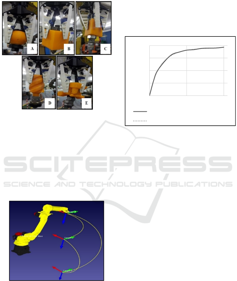
Figure 11: Dynamic test for 4-finger gripper holding a
concentric sphere shape: A) Geometry 1, B) Geometry 2,
C) Geometry 3, and D) Geometry 4.
6.2 Dynamic Testing Preparation
A path plan program is described for the robotic arm
input. The path plan is visually described in Figure
12. The path plan describes a dynamic motion that the
end-effector follows in simulating a pick and place
procedure. The dynamic motion simulates a
controlled experimental environment and the
experiment was repeated multiple times for the same
motion.
Figure 12: Graphical representation of the robotic arm path
plan.
Signal feedback values were received from the
FSR sensors. The voltage and mass loading on the
sensor experienced a non-linear relationship, due to
the shearing of the sensor material, illustrated in
Figure 13. The calibration was conducted for all four
(4) sensors. The voltage output values varied from
one sensor to the other, as a result of the sensitivity in
shear mechanics and material thickness that varied in
each sensor.
Figure 13: Mass verse voltage calibration.
The output value program was calibrated
accordingly to produce a potential value in millivolts.
The following Equation 2 was used to calibrate the
output values:
_
= ( ∗
_
)/1024 ∗ 1000
(2)
Where:
V_out: Output voltage (mV)
val: Value reading output (-)
V_in: Input voltage (5 V)
The relative error for the sensors has been
calculated for 45 readings representing 4.5 seconds
using Equation 3. The object was grasped constantly
to determine the average relative error for the Force
Sensitive Resistors incorporated into the haptic
feedback system for the gripper, shown in Figure 14.
The average relative error was determined for the
mass loading for each sensor and the expected sensor
performance is shown in Table 4.
= 100 × (
−
)/
(3)
Where:
err: Relative error
Val
act
: Value reading
Val
exp
: Expected reading
0
1000
2000
3000
4000
0 500 1000
POTENTIAL DIFFERENCE (mV)
MASS (g)
Sensor Calibration: Mass vs Voltage
Mass verse Voltage
Poly. (Mass verse Voltage)
Active Haptic Control for a Biologically Inspired Gripper in Reconfigurable Assembly Systems - Testing Active Haptic Control through
Force Feedback
87
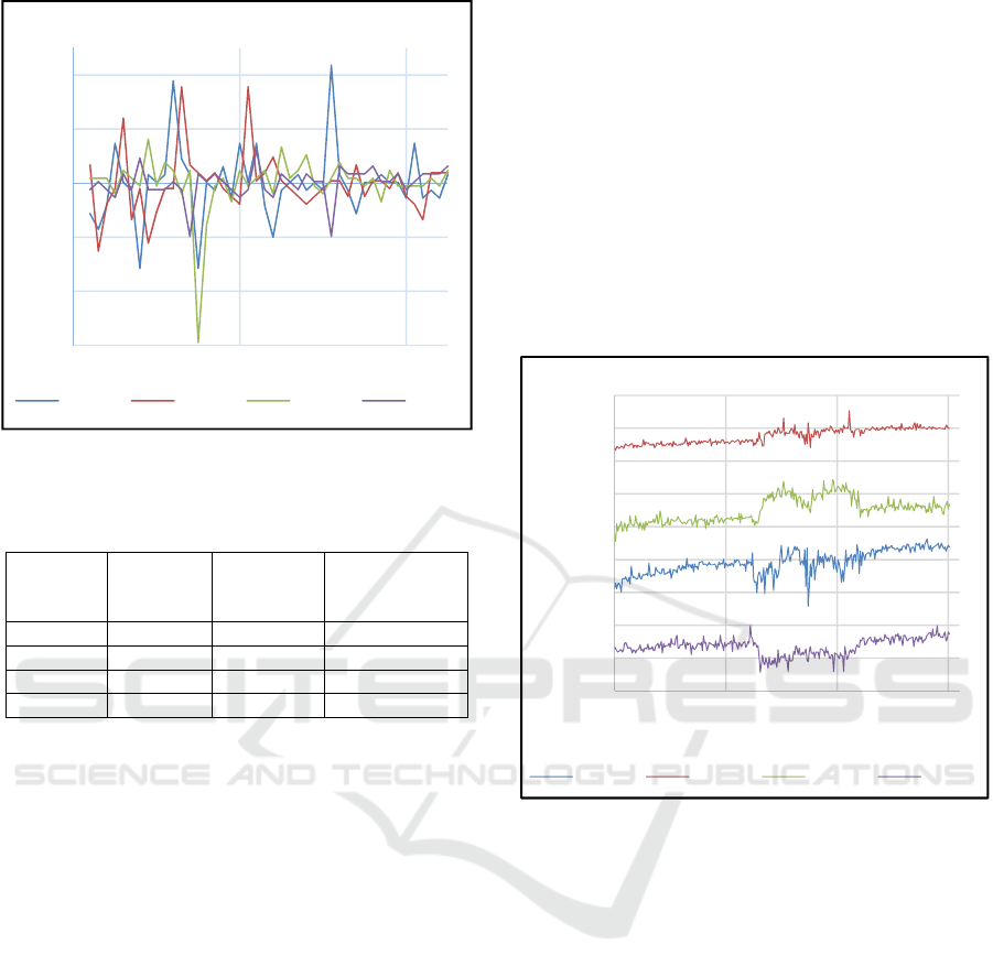
Figure 14: Relative error verse time for FSR sensor 1, 2, 3
and 4.
Table 4: Average relative error for sensor values.
Expected
mass
value (g)
Expected
Voltage
(mV)e
Average
relative error
(%)
Sensor 1
552.25 3378 -0.0003
Sensor 2
429.02 3534 -0.0043
Sensor 3
483.01 3527 -0.0020
Sensor 4
296.08 3173 0.0027
6.3 Dynamic Testing without Feedback
Control
Dynamic testing was performed to determine the
force throughout a dynamic movement without a
feedback control at a low robot speed of 250 mm/s.
The spherical specimen was used as the test piece to
maintain conformity and simultaneous contact of all
four (4) sensors. The object was gripped and cycled
through the movement described in Section 6.2. The
intended movement was described in three (3) time
lapses: A ten (10) second pause, a ten (10) second
dynamic motion and a ten (10) second pause. The
experiment was repeated five (5) times for each
configuration and rib structure to maintain empirical
accuracy.
The data values retrieved to illustrate self-
conformity of the Fin-Ray Effect
®
while grasping
through dynamic motion. Increased voltage
variations display the external force interference due
to the dynamic force components described in Section
3.3. The voltage verse time graph, illustrated in
Figure 15, depicted increased voltage values during
and following the dynamic motion.
An average grip force in grams was calculated to
determine a minimum holding strength. The mass of
the specimen was 320 g and the average holding force
required was 1146 g (286.5 g per appendage).
A disadvantage from the self-conformity
characteristics and high loading variations due to
force interferences is that fragile and brittle
components i.e. lightbulbs have the potential to fail
under varying force and shock loadings. A dynamic
experiment for active haptic feedback control is
required to control the force variation. The control
response is of importance as force changes occur very
rapidly.
Figure 15: Voltage verse time for 4-finger gripper:
Geometry 4 with 250 mm/s speed.
6.4 Dynamic Testing of Active Haptic
Feedback Control
Dynamic testing was performed to determine the
force throughout a dynamic movement utilizing an
active haptic control at a high robot speed of 2000
mm/s. The spherical specimen was used as the test
piece to maintain conformity and simultaneous
contact od fall four (4) sensors. Identical path
planning, estimated time lapses and test runs were
employed that were used in the experiment.
The data values illustrated force control for high-
speed applications, shown in Figure 16. The force
interference was minimized and force increased, due
to self-conformity, was reduced. High signal spikes
were still present as result of noise from the
environment, voltage imbalances from ineffective
material shearing and impaired actuation response.
-3,0
-2,0
-1,0
0,0
1,0
2,0
02040
Realtive error (%)
Deci-seconds (0.1 s)
Relative Error vs Time
Sensor 1 Sensor 2 Sensor 3 Sensor 4
2000
2200
2400
2600
2800
3000
3200
3400
3600
3800
0 100 200 300
Potential Difference (mV)
Deci-seconds (0.1 s)
Voltage vs Time
Sensor 1 Sensor 2 Sensor 3 Sensor 4
ICINCO 2018 - 15th International Conference on Informatics in Control, Automation and Robotics
88
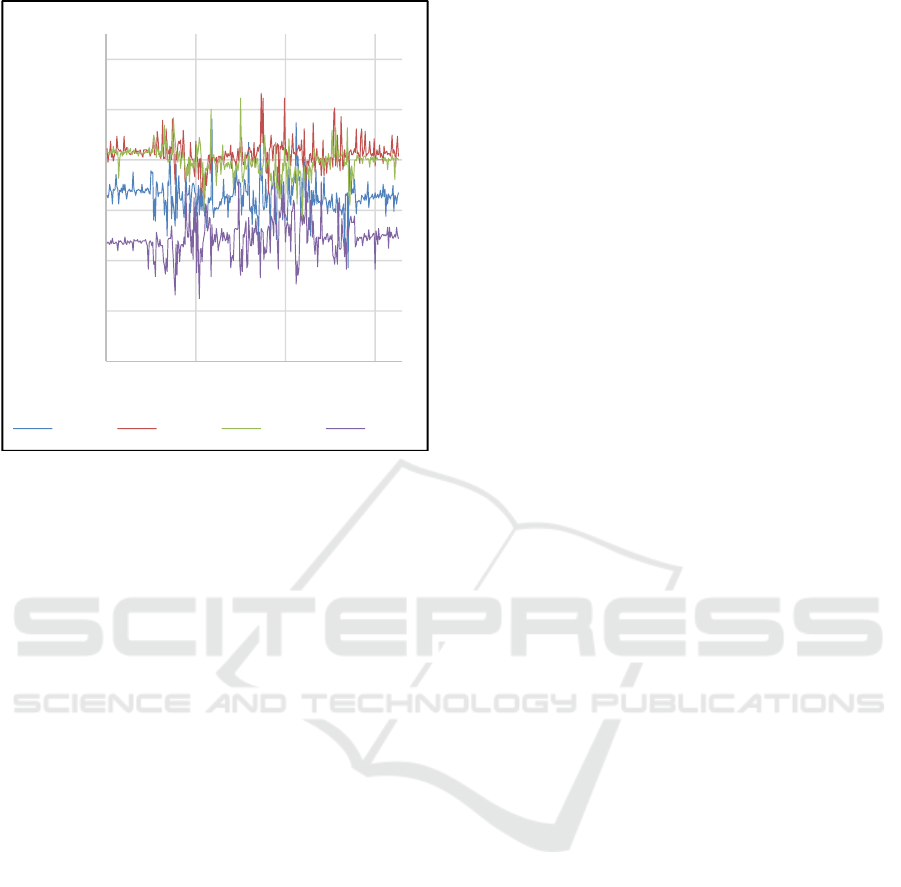
Figure 16: Voltage verse time for 4-finger gripper:
Geometry 4 with 2000 mm/s speed.
The threshold values for the force control are as
follows: Low threshold value (A) was at 977 mV, the
high threshold value (B) was at 3418 (mV) and the
threshold value (C) was at 3345 (mV). The high value
indicated the critical damage value for fragile objects.
The input signal for value (B) is influenced according
to the type of delicate objects that are gripped. The
experiment was repeated five (5) times. Results
illustrated actuation response to force input values to
sensors. Signal values overcoming threshold values
were countered through the opening of the gripper
fingers to reduce high force loading on contact
surfaces.
7 CONCLUSIONS
The paper analysed a haptic feedback control for a
biologically inspired gripper. The gripper was
designed and developed based on the Fin Ray Effect
®
.
The study reviewed conformity characteristic
regarding stress and deflection performed through an
FEA simulation. A haptic feedback control flow
diagram describes the force regulation through
actuation of the gripper. Repeatability of the gripper
was determined through static testing that was
performed in previous studies. The gripper was tested
to verify conformity for grasping of different shapes
in prior investigations. The 4-finger gripper utilizing
Geometry 4 was established to be the preferred
combination.
A dynamic test was performed on the gripper
utilizing force feedback with and without active
haptic control. Testing without active feedback was
performed in prior studies and illustrated force
variation and self-conformity due to dynamic
interferences. High force impulses can potentially
damage fragile components and as a result, an active
haptic feedback control system was required. The
system was tested at lower operational speeds to
emphasise that force fluctuations have involved that
exhibit the potential to damage handled components.
The system was tested employing an active haptic
feedback control and high operational speeds were
exercised in the experiment. The results showed the
force before and after the dynamic motion was
stabilized, but high force impulses were visible
during the movement due to force interferences.
A dynamic test was performed on the gripper
utilizing force feedback with and without active
haptic control. Testing without active feedback was
performed in prior studies and illustrated force
variation and self-conformity due to dynamic
interferences. High force impulses can potentially
damage fragile components and as a result, an active
haptic feedback control system was required. The
system was tested at lower operational speeds to
emphasise that force fluctuations have involved that
exhibit the potential to damage handled components.
The system requires a faster response to force
variation. Force impulses can be minimized by
increased motor speed for opening and closing and
reducing signal noise. The type of sensor used also
affect the sensitivity of the results and higher ranged
force sensors should be used with higher accuracies.
The biologically inspired gripper system with
active haptic control has the potential to be
implemented in production application where
handling of fragile objects is performed. Typical
objects that could be gripped and manipulated in this
investigation are glass components i.e. light bulbs,
fragile foods i.e. eggs, etc.
Haptic feedback control possesses drawbacks
pertaining to environment interaction. Actuator
response to environment requires to be rapid when an
impact occurs. High force impact loading was
observed and as a result affects the control of the
gripper system negatively.
ACKNOWLEDGEMENTS
The authors wish to thank the “Blue Sky Research
Grant” under the grant number 91339.
2700
2900
3100
3300
3500
3700
3900
0 100 200 300
Potential Difference (mV)
Deci-seconds (0.1 s)
Voltage vs Time
Sensor 1 Sensor 2 Sensor 3 Sensor 4
Active Haptic Control for a Biologically Inspired Gripper in Reconfigurable Assembly Systems - Testing Active Haptic Control through
Force Feedback
89

In addition, acknowledgement is given to the
National Research Foundation (NRF) towards this
research.
Opinions expressed and conclusions arrived at,
are those of the authors and not necessarily to be
attributed to the NRF.
The authors’ special thanks are extended to the
staff of UKZN for the opportunity to present their
work.
REFERENCES
Basson, C. I., Bright, G. and Walker, A., 2017.
Investigating Geometric Adaptability for Flexible
Grippers in Reconfigurable Assembly Systems.
Auckland, s.n.
Bouchard, S., 2014. Robotic Gripper Repeatability
Definition and Measurement, Saint-Nicolas: RobotIQ.
Crooks, W. et al., 2016. Fin Ray Effect Inspired Soft
Robotic Gripper: From the RoboSoft Grand Challenge
Toward Optimization. Frontiers in Robotics and AI,
3(70).
FESTO, 2014. MultiChoiceGripper, Esslingen: FESTO.
Koren, Y. and Shpitalni, M., 2010. Design of
Reconfigurable Manufacturing Systems. Journal of
Manufacturing Systems, 29(4), pp. 130-141.
Lipina, J., Tomek, L. and Krys, V., 2011. GRIPPER WITH
ADJUSTABLE GRIP FORCE. Transactions of the
VŠB, LVII(2), pp. 93-102.
Martin, N. A. et al., 2013. Passive Haptic Feedback for
Manual Assembly Simulation. Setubal, s.n.
Molfino, R. M. et al., 1999. Re-engineering Issues in
Automatic Assembly. In: G. Jacucci, G. J. Olling, K.
Preiss and M. Wozny, eds. The globalisation of
Manufacturing in the Digital. Boston: Kluwer
Academic, pp. 603-616.
Molfino, R., Razzoli, R. P. and Zoppi, M., 2006. A Low-
Cost Reconfigurable Gripper for Assembly and
Dissambly Tasks in White Industry. IFAC Proceedings
Volumes, 39(15), pp. 498-505.
Padayachee, J. and Bright, G., 2013. The Design of
Reconfigurable Assembly Stations for High Variety
and Mass Customisation Manufacturing. South African
Journal of Industrial Engineering, 24(3), pp. 43-57.
Park, T. M., Won, S. Y., Lee, S. R. and Sziebig, G., 2016.
Force Feedback-Based Gripper Control on a Robotic
Arm. Budapest, IEEE 20th Jubilrr International
Conference on Intelligent Engineering Systems (INES).
Pfaff, O., Simeonov, S., Cirovic, I. and Stano, P., 2011.
Application of Fin Ray Effect Approach for Production
Process Automation. Vienna, Annals of DAAAM
Proceedings.
Reddy, P. V. and Suresh, V. V., 2013. A Review on
Importance of Universal Grippers in Industrial Robot
Applications. International Journal of Mechanical
Engineering and Robotics, 2(2), pp. 255-264.
Saddik, A. E., 2011. Haptics Technologies. In: Haptics:
General Principles. Berlin: Springer-Verlag, pp. 1-20.
Staretu, I., 2015. Anthropomorphic Modular
Reconfigurable Grippers with Three and Four Fingers
- Design and Prototype. Bucharest, s.n.
Tharayil, V. et al., 2017. Design, Fabrication and Analysis
of Three Fingered Fin Gripper for KUKA KR6 R900
Robot. SSRG International Journal of Mechanical
Engineering - (ICETM-2017) , Issue Special Issue, pp.
42-44.
Xia, P., 2016. Haptics for Product Design and
Manufacturing Simulation. IEEE TRANSACTIONS ON
HAPTICS, 9(3), pp. 358-375.
Yang, C., Ma, H. and Fu, M., 2016. Advanced Technologies
in Modern Robotic Applications. Singapore: Springer.
Yan, S., Yang, T., Liu, X. and Wang, R., 2012. Tactile
Feedback Control for a Gripper Driven by SMA
Springs. AIP Advances, 2(3).
Yeung, B. H. and Mills, J. K., 2004. Design of a Six DOF
Reconfigurable Gripper for Flexible Fixtureless
Assembly. IEEE Transactions on Systems, man, and
Cybernetics - Part C: Applications and Review, 34(2),
pp. 226-235.
ICINCO 2018 - 15th International Conference on Informatics in Control, Automation and Robotics
90
