
Vision-inertia Virtual Glasses Relative Attitude Estimate within a
Rotation Free Cabin
Keqiang Wu
1
, Hai Zhang
2
and Youze Mao
3
1
School of Automation Science and Electrical Engineering, Beihang University, Beijing, China
2
Science and Technology on Aircraft Control Laboratory, Beihang University, Beijing, China
3
Beijing Institute of Electronic System Engineering, Beijing, China
wukeqiang@buaa.edu.cn, zhanghai@buaa.edu.cn, myz19841984@163.com
Keywords: Inertial measurement unit, Optical tracking system, Fusion, Relative attitude, Virtual reality.
Abstract: This paper presents a visual and inertial measurements fusion scheme to estimate the relative attitude when
the cabin and the virtual glasses in it are both free to move. A Euler angle filter is designed when the cabin
rotation rate can be provided with high frequency. Another orientation error filter is developed when only
the cabin attitude can be obtained. Both of these algorithms are based on low cost MEMS inertial
measurement unit, experiment has proved that the relative attitude can be fast and accurately estimated. The
main advantages are the measurement noise can be well suppressed and the relative attitude estimation can
be continuous even though the glasses are invisible to the optical tracking system.
1 INTRODUCTION
One of the key requirements in applications of
virtual reality (VR) and augmented reality is attitude
measurement (Chai et al., 2002; Himberg et al.,
2013), which cares more about the accuracy and
speed (Carrillo et al., 2012). In augmented reality, a
system not only tracks the orientation of the user’s
head but also estimates the 3D structure of the scene,
where robust relative pose estimation is a core
requirement as well as a significant challenge
(Huster et al., 2003). In order to increase the user's
immersion, some VR devices are equipped with
rotatable cabin, which makes it possible to create a
more lifelike experience in flight and vehicular
applications. As a result, the relative attitude
between VR glasses and cabin is essential for the
system to provide the pilot's point of view.
Vision-inertia fusion based relative attitude
between VR glasses and cabin is a good method to
cope with invisible or rapid moving situations. High
frequency inertial calculation, calibrated by and
fused with visual measurements, can cover accuracy
and speediness in a very cost effective way.
Fusion of inertial and other sensors is needed in
many applications. Armesto et al. (2007) investigate
the multi-rate problem in their fast ego-motion
estimation fusion system. Moreover, Foxlin et al.
(1998) designed a tracking system based on an
inertial navigation system aided by ultrasonic time-
of-flight range measurements. An unscented Kalman
filter is proposed for robust estimation of position
and orientation of moving target in surgical
applications (Enayati et al., 2015). Gebre-Egziabher
et al. (2004) proposed an inexpensive multi-sensor
attitude determination system consisting of gyros
and an aiding system.
Although considerable works have been done to
get good fused outputs, improvements can also be
done, especially for the complex situations, which
conventional methods cannot deal with and are
seldom published, of cabin moving and multi object
tracking.
A bewildering number of motion-tracking
technologies have been designed for different
purposes, including inertial tracking systems
(Roetenberg et al., 2009), active magnetic trackers,
and optical tracking systems (OTS), and so on.
Inertial measurement unit (IMU) have become
particularly popular because of low-cost and small-
size. However, all the nonideality, such as noise,
gravity compensation error, bias, and calibration
error are accumulated due to the inevitable
integration of inertial data, yielding an ever
increasing drift. OTS commonly consists of two
components: 1) light sources and 2) optical sensors.
The light sources might be active markers that emit
light or passive markers that reflect ambient light.
536
Wu, K., Zhang, H. and Mao, Y.
Vision-inertia Virtual Glasses Relative Attitude Estimate within a Rotation Free Cabin.
In 3rd International Conference on Electromechanical Control Technology and Transportation (ICECTT 2018), pages 536-540
ISBN: 978-989-758-312-4
Copyright © 2018 by SCITEPRESS – Science and Technology Publications, Lda. All rights reserved

One example of these is distinguishable fiducials in
the board and sensors are often multiple charge-
coupled device cameras. The vision-based tracking
system has advantages such as being disposable,
having no wiring. However, it suffers from a
requirement of clear line of sight, and high
computational expense. Combining visual
measurements with IMUs can improve the quality,
reliability, and robustness of tracking system.
In this paper, two kinds of relative attitude
estimate schemes are designed to cope with the joint
movements of a cabin and VR glasses. Based on
additional low cost IMUs, real-time and accurate
relative attitude estimate can be guaranteed.
2 SENSOR FUSION METHOD
There are three components in the system including
a pair of VR glasses, a cabin and an optical tracking
system. The VR glasses are equipped with a 3-ais
gyroscope and accelerometer MEMS IMU, and its
relative attitude can usually be measured by the OTS
installed in the cabin except for invisible situations.
End-to-end delay and high computational expense
are still obstacles for OTS, especially those
commercial ones. Because a low IMU suffers from
drift, only inertial calculation cannot guarantee the
accuracy (Welch et al., 2002). Therefore, visual
inertial integrated mode is a good choice.
2.1 Reference Frames Involved
A pose and an inertial measurement can be
expressed in different coordinate frames with
diverse shapes. Relative attitude estimation involves
glasses, cabin and inertial space, which are defined
in different frames. The definitions of these right-
handed Cartesian frames are listed as below.
VR frame{v}:fixed to VR glasses and
defined by the optical markers;
Body frame {b}:fixed to cabin;
Earth frame {e}:fixed to Earth rotating at a
speed of
relative to the inertial reference
frame;
Navigation frame {n}: a local frame denoting
the Earth’s geoid. The origin of the frame moves
with the system.
IMU measures the angular rate of the VR frame
with respect to the inertial frame. The OTS reports
the pose of the VR frame with respect to the body
frame. The cabin can provide its pose with respect to
the navigation frame and angular rate with respect to
the inertial frame. In order to take the measurements
of the sensors into a single coordinate system for the
fusion, the transformation
b
v
R
between the VR frame
and the body frame is needed.
It is assumed throughout this work that the error
of cabin’s pose and angular rate can be ignored. The
IMU is assumed to measure without latencies.
The angular rate model is
() () () ()
vvvv
bn
kkkkω ωωω
(1)
where
()
v
kω
is the measurement vector,
()
v
kω
is
the true vector,
()
v
b
kω
is the sensor biases vector,
and
()
v
n
kω
is the measurement noise vector. The
superscript v denotes that the reference frame is VR
frame. The OTS measurements were modelled
simply with additive noise terms.
2.2 Relative Attitude Filter
The outputs of the OTS are Euler angles of yaw,
pitch and roll with respect to body frame, which are
enough to represent any rotation in 3-D space. Using
these data, the filter computes an estimate of the
system state vector X.
T
bv
r
X φ b
(2)
where
bbbb
rrrr
φ
represents yaw, pitch
and roll of VR glasses along the body frame and
v vvv
x
yz
bbb
b=
is IMU angular rate biases
vector along the VR frame. The continuous-time
kinematic equations are
0
=( )
bvv
rbv
φ G ω b
v
b
bw
(3)
where vector
b
w is Gaussian variables and
v
bv
ω
denotes relative angular rate between the VR frame
and the body frame along the VR frame, which can
be computed using the outputs of the IMU
v
iv
ω
vv
bv iv
vb
bbi
ωωR ω
(4)
where
i denotes the inertial frame, and
b
ib
ω
can be
got from the cabin.
Vision-inertia Virtual Glasses Relative Attitude Estimate within a Rotation Free Cabin
537

The
0
G is a matrix based on relative attitude and
can be written as
sin cos
0
cos cos
cos 0 sin
tan sin 1 tan cos
bb
rr
bb
rr
bb
rr
bb b b
rr r r
0
G
(5)
And
v
b
R
is the direction cosine matrix, which
denotes the transformation from body frame to VR
frame.
The discretized first order state equation is
1
bbb
rk rk rk
dt
φφφW
1kk
bb
(6)
where
dt
is the time interval, and
W
denotes
process noise.
The measurements come from OTS and can be
written as
+
b
krkk
ZHφ v
(7)
where
kmmm
Z
is the output of the OTS
and
k
v
is the measurement noise with covariance
of
k
R ,and
H
is an identity matrix.
2.3 Orientation Error Filter
Since vision-based tracking system suffer from high
computational expense. It is not easy to get the
measured value in high frequency. What's more, in
some systems, the angular rate of the cabin can
hardly get. An attitude error filter was proposed for
adapting to the low frequency measurement, where
the Kalman filter optimally estimates attitude errors
of the VR glasses as well as the bias of the IMU.
The system state vector
X
of the filter is composed
of orientation error and IMU bias. The orientation
error is represented with small Euler angle
φ
and
the relation between orientation error and
transformation
n
p
R
is
[]
E
NU
φ
1
1
1
UN
n
p
UE
NE
R
(8)
The inertial strapdown algorithm is implemented
in the presented approach for processing raw IMU
data and providing yaw, pitch and roll angle, which
can be used to compute the direction cosine matrix
v
p
R
between the platform frame and the VR frame.
The orientation in our strapdown solution is
represented with quaternions
k
q , which is singularity
free. The INS error model is implemented in the
solution, which follows the approach proposed by
Bar-Itzhak and Berman (1988).
nn
in b b G
φω φR ε +R W
(9)
where
ε
denotes the gyro drift error,
in
ω is the
rotation vector from the navigation to the inertial
frame, and
G
W is process noise sequence.
The direction cosine matrix
n
b
R
between the body
frame and the navigation frame can be computed
using the outputs of the cabin. Thus, the
measurement
kENU
Z
can be extracted
from the transformation
n
p
R
, which is given by
nnbv
p
bv p
RRRR
(10)
As a result, the measurement model can use a
simple linear model
+
kk
k
ZHδφ v
(11)
where
H
is an identity matrix, and
k
v
denotes the
stochastic noise term for the measurements of
orientation error with covariance of
k
R . However, it
is not easy to get
k
R since the direct observation is
rrrr
φ
of which the noise and its variance
are
=
T
rrrr
WWW
W
and
=
T
rrr
σ
. But
k
v
can be described by
123
=
k
T
rr
TvWtttW
(12)
where
1
t ,
2
t ,
3
t are row vectors with three elements.
The coefficient matrix
123
tt t
is obtained by
using the error transfer formula of mathematical
statistics.
ICECTT 2018 - 3rd International Conference on Electromechanical Control Technology and Transportation
538
1 1 11 11 1
22 22 22 2
33 33 33 3
nnn
ppp
rrr
nnn
ppp
rrr
nnn
ppp
rrr
t
t
RRR
tl ml ml m
RRR
lmlmlm
RRR
lmlmlm
(13)
where
123
011 101 110ll l
123
11 1 1 11
[0 ] [ 0 ] [ 0]
22 2 2 22
TTT
mm m
As a result, it is easy to obtain
k
R by
{}{ }
kk
TTT
krr
EETWWT
Rvv
(14)
Clearly, the two filters have different require-
ment for the measurements. The relative attitude
filter is suitable when the cabin rotation rate and
vision data can be provided with high frequency,
while orientation error filter have better performance
when visual measurement frequency is low.
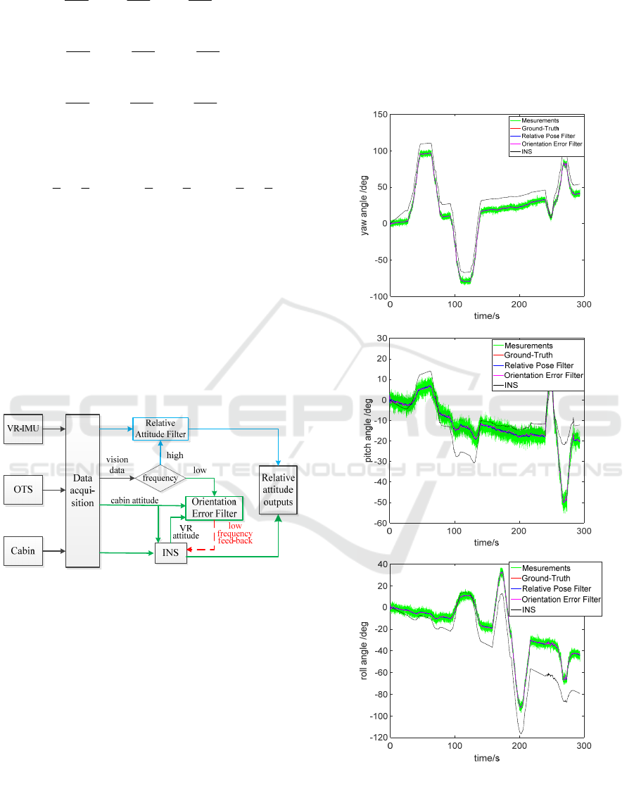
Figure 1
display the main procedure of the fusion system.
iv b
v
i
b
ω ,ω
b
ib
ω
Figure 1: Inertial and vision fusion system scheme.
3 EXPERIMENTAL RESULTS
The proposed fusion algorithm is verified with a
predefined set of rotational movements at different
speeds. In particular, three degrees of freedom of
movement, yaw, pitch and roll is studied in the
experiments. The general sampling rate of the IMU
is 50Hz, and the sampling rate of the optical sensor
selected is 50Hz and 5Hz respectively in relative
pose filter and orientation errors filter.
It can be directly inferred form Fig2~3 that the
performances of both relative pose filter and
orientation error filter are obviously superior to the
visual measurements, considering the average error.
Besides, the proposed methods have a short reaction
time, which converges fast to stable values. It can
also be concluded that orientation error filter uses
visual measurements with fewer frequency but get a
similar accuracy with relative pose filter, which
improves the computational efficiency of orientation
error filter.
Figure 2: Yaw, pitch and roll angle estimate result.
Vision-inertia Virtual Glasses Relative Attitude Estimate within a Rotation Free Cabin
539
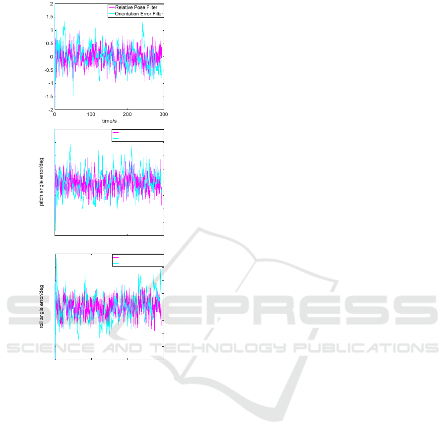
Figure 3: Yaw, pitch and roll angle error.
4 CONCLUSIONS
In this paper, two inertial and vision data fusion
algorithms are proposed for attitude measurement.
Kalman Filter is employed for data fusion, and
different methods are designed to adapt the high
frequency or low frequency of visual data. In
orientation error filter, the state error and residual
are updated once there are visual measurements, and
then the residual can be used to compensate
estimated attitudes. Comparing with relative pose
filter, the state was optimal estimated every frame.
In order to validate the performance of the two
filters, the trajectory with three degrees of freedom
is designed. The experimental results show that
high-precision in comparison with visual data can be
obtained by the proposed methods. And orientation
error filter could work well with even lower
frequency of visual data, which confirm the
computational efficiency and reliability of the
proposed method.
ACKNOWLEDGEMENTS
This work is partially supported by the National
Key Research and Development Program of China
with a grant number as 2016YFB0502004 and
partially supported by the National Natural Science
Foundation of China with a grant number as
61320106010.
REFERENCES
Chai, W. A. Hoff, and T. Vincent, 2002. 3-D motion and
structure estimation using inertial sensors and
computer vision for augmented reality. In Presence-
Teleoperators and Virtual Environments.
Himberg, H., Motai, Y., Bradley, A. A., 2013. Multiple
Model Approach to Track Head Orientation With
Delta Quaternions. IEEE Transactions on Cybernetics,
43(1):90.
Carrillo, R. G., Lopez, A. E. D., Lozano, R. and Pegard,
C., 2012. Combining stereo vision and inertial
navigation system for a quad-rotor UAV. In Journal of
Intelligent & Robotic Systems, 65(1), 373–387.
Huster, A., 2003. Relative position sensing by fusing
monocular vision and inertial rate sensors, Stanford
University.
Armesto, L., Tornero, J., Vincze, M., 2007. Fast Ego-
motion Estimation with Multi-rate Fusion of Inertial
and Vision, Sage Publications, Inc.
Foxlin, E., Harrington, M., and Pfeifer, G., 1998.
Constellation: A wide-range wireless motion-tracking
system for augmented reality and virtual set
applications. 371–378.
Enayati, N., Momi, E. D. and Ferrigno, G., 2015. A
quaternion-based unscented Kalman filter for robust
optical/inertial motion tracking in computer-assisted
surgery. In IEEE Transactions on Instrumentation &
Measurement. 64(8), 2291.
Gebre-Egziabher, D., Hayward, R. C. and Powell, J. D.,
2004. Design of multisensory attitude determination
systems. In IEEE Transactions on Aerospace
Electronic Systems. 40(2):627-649.
Roetenberg, D., Luinge, H., Slycke, P., 2009. Xsens mvn:
full 6dof human motion tracking using miniature
inertial sensors. Xsens Motion Technologies Bv.
Welch, G., Foxlin, E., 2002. Motion tracking: No silver
bullet, but a respectable arsenal. In Computer
Graphics & Applications IEEE. 22(6):24-38.
Baritzhack, I. Y., Berman, N., 1988. Control theoretic
approach to inertial navigation systems. Journal of
Guidance Control & Dynamics, 10(10), 1442-1453.
yaw angle error/deg
0 100 200 300
time/s
-2
-1.5
-1
-0.5
0
0.5
1
1.5
2
Relative Pose Filter
Orientation Error Filter
0 100 200 300
time/s
-2
-1.5
-1
-0.5
0
0.5
1
1.5
2
Relative Pose Filter
Orientation Error Filter
ICECTT 2018 - 3rd International Conference on Electromechanical Control Technology and Transportation
540
