
Study on Crack Leakage of Aircraft Hydraulic Pipeline
Zhao Jinfang
1,*
, Li Chong
1,2
, Sun Dan
1
, Fu Xiaopu
2
and Tian Linhui
2
1
Civil Aviation College, Shenyang Aerospace University, Shenyang, China
2
General Assembly Workshop, Shijiazhuang Haishan Industrial Development Corporation, Shijiazhuang, China
Keywords: Aircraft Hydraulic Pipeline, Crack Leakage, Maintenance Strategy.
Abstract: The problem of aircraft hydraulic pipe is one of the frequent problems in the daily maintenance process. After
a long flight, it will gradually expose structural scratches, pipe extrusion, longitudinal cracks, oil leakage,
blasting, etc. Based on the big data of the quality report of a single flight, this paper studied the main causes
of cracks at the root of the flat nozzle, and proposes targeted improvement measures from the structural layout,
operation mode, typical leakage. ANSYS simulation shows that the root of the flat nozzle of the guide pipe
is at the rear of the fuselage under different frequencies and forces. The equivalent stress and elastic defor-
mation were observed by metallography analyzer and X-ray spectrum analyzer. It was concluded that under
the installation stress of the tube itself, the root of the nozzle of the flat tube would produce extrusion friction
with the tube under the condition.The tube body was resonated with the body of the body, leading to the
fracture from the outside to the inside.
1 INTRODUCTION
The aircraft hydraulic pipeline system is the main ex-
ecutive system of the aircraft to complete various ac-
tions, which provides the pilot with the control and
power assistance of the aircraft. The fuselage of the
military aircraft is covered with densely packed avia-
tion pipelines, the number of individual aircraft pipes
about 2000, about 800 straight-through joints, which
is particularly large. After a long flight, quality prob-
lems are gradually exposed. For example, hydraulic
pulsation is very harmful to the hydraulic system,
which not only degrades the dynamic characteristics
of the system, affects the service life of the compo-
nents and pipelines, but also causes resonance or res-
onance to damage the system components, even par-
alyzes the system and causes catastrophic accidents
(Cheng et al., 2011). In the past two years, there were
120 oil leakage faults fed back from the outfield of a
certain type of aircraft. The major accidents caused
by the pipeline system accounted for 38% of the total
faults. The root cracking of nozzle is one of the most
common feedback problems follewed by pipe explo-
sion.
2 RELATED WORK
2.1 Analysis of Aircraft Hydraulic
Pipeline Problems
Flared connection is the most widely used connection
method in the active aircraft hydraulic system (Chen
et al., 2021). According to the data analysis, the explo-
sion of the aircraft hydraulic system mainly occurs at
the attachment connection, the connection of the hy-
draulic pipe around the engine, the connection of the
suspension straight pipe and the three-way pipe (Quan
et al., 2020), secondly, it occurs at the dense connec-
tion of the hydraulic fuel pipe, which produces friction,
which generates friction, indentation, compression,
pulse, etc. due to the restriction of the structural space.
The main problems focus on the following aspects.
In the actual operation of the project, during the
quarterly general inspection and spot-check of the
pipe disassembly, it was found that there was stress
assembly in many pipes, and forced assembly was
carried out without qualified adjustment in the pro-
cess, which also indicated that the stress release was
not achieved during the flight (Xia et al., 2021). Due
to the restriction of space, the installation of hydraulic
system pipelines is inconvenient and prone to friction,
which is mainly manifested in severe pressure pits,
Jinfang, Z., Chong, L., Dan, S., Xiaopu, F. and Linhui, T.
Study on Crack Leakage of Aircraft Hydraulic Pipeline.
DOI: 10.5220/0011955700003536
In Proceedings of the 3rd International Symposium on Water, Ecology and Environment (ISWEE 2022), pages 187-191
ISBN: 978-989-758-639-2; ISSN: 2975-9439
Copyright
c
2023 by SCITEPRESS – Science and Technology Publications, Lda. Under CC license (CC BY-NC-ND 4.0)
187
friction of structural stringers, wear through and com-
pression of peripheral pipelines (Heng, 2014). The
cause of the problem comes from the deficiencies in
the aircraft design.Most of the special frequently oc-
curring pipelines are located behind the inlet with
strong vibration, and the inlet is the boundary, except
for the front part of the fuselage of the main landing
gear, they are more stable (Meng et Yang, 2022). The
leakage rate of the rear fuselage is 85% of that of the
whole fuselage, and the tube is installed near the air-
craft engine, and the working temperature is about
550°C. The flat nozzle is an integral life part of air-
craft, which is easy to produce longitudinal fatigue
crack in its horn and pipe bushing (Liu and Xao,
2016). The failure fluctuates during the training pe-
riod. The failure of the aircraft just completed the test
flight is extremely low. When the flight time is 300h-
400h, the failure rate of the aircraft is high, and the
failure rate increases with time. The cause of correc-
tion is related to failure on the one hand and stress
assembly in actual operation on the other hand.
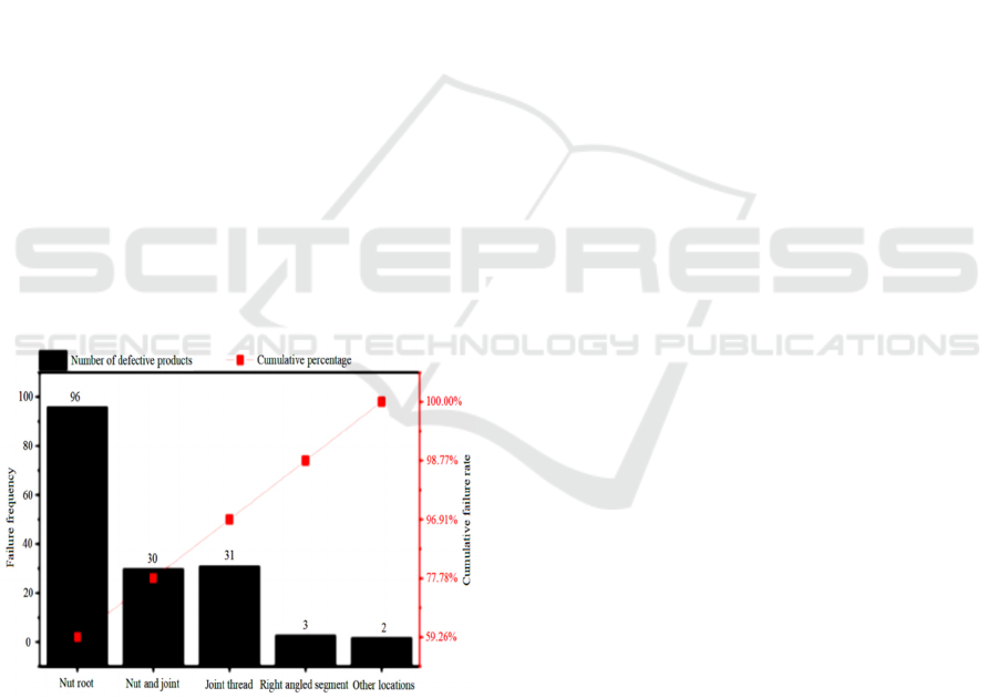
The occurrence of problems can be described as
diverse and complex. According to the statistical
chart of oil leakage locations as shown in Figure 1,
the oil leakage at the root of the nut accounts for 59%
of all oil leakage locations. The root of the nut is the
location where the nut contacts the flat nozzle. It can
be seen that the contact between the nut and the pipe-
line is the main problem of oil leakage at the joint
with lock nut(Chen, 2021; Du et al., 2021).
Figure 1: Statistical Diagram of Oil Leakage Location.
2.2 Analysis of Crack State of Aircraft
Pipeline
2.2.1 Post Damage Caused by Aircraft
Engineering Specifications
The aircraft hydraulic pipeline can be installed in two
ways, the first is divided by system, and the second is
divided by location. The hydraulic system installed
according to the system division is assembled by a
single operator, who will adjust and control according
to the overall length; The hydraulic system installed
according to the location division is usually assem-
bled by multiple operators. For example, one operator
is responsible for the front of the air inlet and another
operator is responsible for the rear of the air inlet.
This will lead to poor stress control on the pipeline
butt joint after the hydraulic system is assembled.
Sometimes, it can not even be assembled normally,
and the pipe can only be sawed for new assembly.In
the process of pipe assembly, some aluminum alloy
pipes are affected by the manufacturing tolerances of
pipe materials and flat nozzles, as well as the manu-
facturing errors of flared taper, outer sleeve nuts and
straight joints.Therefore, the fit gap between the pipe
and the flat nozzle tube will be randomly distributed,
and there are different coaxial phenomena, once it
happens, it is an accident sign(Du et al., 2021). From
the project management mode, the first operation as-
sembly mode is to install according to the system di-
vision, the whole hydraulic system installation by the
operator single assembly, will be adjusted according
to the overall length of processing; The second is di-
vided by position, such as one operator before the in-
take port and another operator after the intake port,
after the assembly of the hydraulic system, the con-
nection of the two pipelines will result in poor control
and produce stress, sometimes resulting in stress in-
stallation. If the normal assembly can not be
achieved, the saw pipe can only be reassembled, so
most of the stress is difficult to control, complex pipe-
line network even more than 10 mm there will be a
big problem. At the same time, some aluminum alloy
pipes are affected by the manufacturing tolerance of
pipe material, flat nozzle, taper deviation of flaring,
outer nut and straight through joint and so on, the fit
gap between the pipe and the flat nozzle will be ran-
domly distributed, and the pipe and the flat mouth
tube have different axis phenomenon (Du et al.,
2021). When it happens, it is a symptom of an acci-
dent.
In the outfield flight mission, it was reported that
more pipeline cracks were generated at the root of the
flat nozzle. At the same time, it was found that there
were metal chips like foreign matters with the same
material as the pipeline between the pipeline and the
flat nozzle, mainly concentrated in the longitudinal
cracks between the pipeline and the bushing, and the
cracks between the pipeline and the bell mouth. Due
to the deformation caused by vibration, pulling and
force, the pipeline cracks often occur at the root of the
ISWEE 2022 - International Symposium on Water, Ecology and Environment
188

sleeve. Figure 2 shows the internal morphology of
high circumferential cracks.
Figure 2: High cycle crack at sleeve root.
The reason for the crack at the root of the flat noz-
zle is that there is a stress at this position, which
causes the extrusion between the pipeline and the flat
nozzle. In addition, the aircraft will generate vibration
during flight. The two factors act at the same time,
causing the abrasion of the pipeline and eventually
leading to the breakage of the pipeline.
2.2.2 The Frequent Problems of Pipelines
Leakage
After the actual assembly, the stress of the aircraft
will be released after a long period of pressure. How-
ever, if the release is not complete enough, the vibra-
tion of the aircraft and the start of the engine will
cause great vibration damage to the hydraulic pipe. If
the problem of excessive stress is encountered, the
operator will usually fine tune the angle or select the
saw tube installation. At present, L2FM pipes in
China are often found with surface defects such as in-
dentation, scratch and other problems in the process
of use, which are caused by cracks in the pipe under
the vibration environment after the aircraft has been
flying for a long time.
The pipeline for body installation is divided into
formed tubes and non formed tubes. There are strict
requirements for unformed pipes to be self calibrated.
The bending radius should not be less than 3d (d is
the diameter of the pipe). The linear distance from the
beginning of the pipe bending to the flat nozzle
should not be less than 5mm. The pipe should not be
twisted after connection. The cause of scratches is
usually that the bending radius is too small, and the
stress is formed at the root of the catheter and the
sleeve, which causes the pipe to bend directly at the
sleeve, resulting in root leakage.
2.2.3 Leakage Caused by Repair and
Maintenance
In order to improve the maintenance efficiency and
eliminate the leakage in time, the maintenance per-
sonnel usually dismantle the pipeline at the connec-
tion and then forcibly connect it. This process often
does not consider the requirement of force limitation.
Such disassembly and assembly will not only cause
transverse cracks at the pipe bell mouth, but also eas-
ily lead to sudden changes in the contact surface, re-
sulting in pressure or contact clearance, which will
lay hidden dangers for safe flight. For example,
When disassembling the two-way connecting pipe-
line, if the two ends of the fixing nut are forcefully
disassembled, the pipeline about 10mm behind the
bell mouth at the other end will be bent at 60°, and
even if it is recovered, there will be poor contact.
3 METHODOLOGY
3.1 Control Measures to Prevent
Pipeline Damage in the Later Stage
According to the theory of total quality management,
the factors affecting the damage of the pipeline are
studied, and the damage caused by vibration or wear
is controlled through feedback improvement.
3.1.1 Improve Maintenance Project
Management Mode
A typical "star" pipe after complete installation is
tested for stress compliance during installation.
(1) 70% of the faults in the hydraulic system are
caused by the oil pollution of the hydraulic system.
Therefore, it is extremely important to strengthen the
control of oil pollution and surplus in the production
process to improve the reliability of the hydraulic sys-
tem. The timing of oil filter connection shall be
strictly controlled (Zhu et al., 2015). The equipment
shall replace the oil filter in strict accordance with the
implementation standards to avoid the frequent infil-
tration of surplus materials into the system.
(2) Adjust the process to avoid multiple disassem-
bly and assembly in the later period, which may lead
to poor contact of the catheter. The pipeline shall be
strictly checked to see if there is scratch inside it and
if there is cone indentation.
(3) The important connection position of the pipe-
line more or less caused uneven stress release due to
improper adjustment in the early stage, resulting in
Study on Crack Leakage of Aircraft Hydraulic Pipeline
189

smaller gap and larger stress at the connection. The
system connection can release the whole to the opti-
mal configuration range to solve this problem. The
pulsating production line shall be established for the
installation of hydraulic pipelines to avoid the whole
machine spreading for operation as far as possible.
The accessories of the hydraulic system department
shall be taken as the starting point for treatment, and
the work rhythm shall be adjusted to improve the
quality of pipeline maintenance.
(4) The pipeline shall be protected in a timely
manner by professional binding, and the paint at the
root of the pipeline shall be repaired in a timely man-
ner to prevent corrosion of the pipeline caused by
moisture, acid and alkali substances. In addition, dust
and air shall be prevented from entering the system.
3.1.2 Ensure the Process Control of Pipeline
The pulsatile production mode can realize the trans-
formation of the position set by the system, so as to
reduce the excessive stress at the junction.
(1) Correct sizing and stress relief of the pipeline.
Due to the influence of the material of the hydraulic
pipe itself and the large bearing pressure, there is a
large stress in the hydraulic pipe during flight, which
may lead to air blasting. When installing the pipeline,
install the nut, and then gently pull it with your hand
to conduct stress free installation. Do not force instal-
lation.
(2) Strictly enforce the torque requirements of the
pipe, do not bear too much force, according to the
pipe diameter to apply a considerable force, in prac-
tice due to poor contact, want to use the way of screw
die is not right, there are also short horn, stud
scratches generated by the surplus caused by system
pollution. Each type of pipe has torque requirements,
according to the different torque to tighten.
(3) Each type of pipeline has torque requirements,
which shall be tightened in strict accordance with the
torque requirements of the pipeline, and excessive
force is not allowed. In actual operation, it is not ad-
visable to deal with the problem of poor contact by
screwing the nuts. This practice will cause the stud to
scratch and produce surplus material, which will
cause system pollution.
(4) For the pipelines near the engine, try to avoid
the hard connection mode of empty three-way and
four-way pipes. If this mode is necessary, fix the
three-way and four-way pipes on the engine body and
accurately measure the distance (Zhang et al., 2019).
(5) If the pipeline leaks, the cause shall be ana-
lyzed in a timely manner, and the troubleshooting
cannot be carried out simply by tightening. In addi-
tion, protection measures shall be taken during instal-
lation to prevent foreign matters from entering the
system and damaging the inner wall. The causes of
frequent catheter damage should be found by combin-
ing data analysis.
4 CONCLUSIONS
Pipeline failure is a system engineering, and the fail-
ure process is relatively complex, usually caused by
multiple factors. There is no obvious plastic defor-
mation in the fatigue crack of the pipeline. Without
obvious signs before fracture, it will suddenly cause
damage, and the fatigue fracture stress is very low,
often lower than the yield strength under static load.
ACKNOWLEDGEMENTS
This work was financially supported by Scientific re-
search fund project of Liaoning Provincial Depart-
ment of Education (JYT2020122); Shenyang Aero-
space University introduction talent scientific re-
search start-up fund project (20YB20).
REFERENCES
Cheng R, Wang X, Yin Z. (2011). Cause Analysis and So-
lution of L15 Higher Education Machine Hydraulic
Pulse Exceeding the Standard [J]. Trainer, (01): 46-49.
Chen D, Yang J, Li W, et al. (2021). Research on connec-
tion simulation and structural parameters of aviation
flared conduit [J]. Journal of Sichuan University of
Light Chemical Technology (Natural Science Edition),
34 (04): 25-31.
Quan L, Che S, Guo C, et al. (2020). Axial Vibration Char-
acteristics of Fluid-Structure Interaction of an Aircraft
Hydraulic Pipe Based on Modified Friction Coupling
Model[J]. Applied Sciences, 10(10): 35-48.
Xia Z, Fan X, Zhao X, et al. (2021). Simulation Analysis of
Multi factor Influence Law on Pipeline Sealing of Air-
craft Hydraulic System [J]. Aerospace Precision Man-
ufacturing Technology, 57 (03): 5-10.
Heng B. (2014). Finite element simulation analysis of con-
nectors and pipelines of aircraft hydraulic system [D].
Nanjing University of Aeronautics and Astronautics.
Meng Q, Yang G. (2022). Fault diagnosis method of hy-
draulic pipeline based on LSTM neural network model
[J]. Electromechanical Engineering, 1-9.
Liu Z, Xiao J. (2016). Failure analysis of flat nozzle crack
in high temperature zone [J]. Economic and Trade
Practice, (22): 238.
ISWEE 2022 - International Symposium on Water, Ecology and Environment
190

Chen D. (2021). Mechanical response analysis and struc-
tural optimization of aviation flared pipe joint [D].
Southwest Jiaotong University.
Du J, Sun T, Tan Y, et al.(2021). Failure analysis of circum-
ferential fatigue cracking of flared 5A02 aluminum al-
loy conduit [J]. Light alloy processing technology, 49
(04): 38-43.
Zhu Z, Tao Y, Wang X, et al.(2015) The importance of pro-
duction process is seen from the maintenance of avia-
tion hydraulic pipe [C]. Proceedings of the Seminar on
Aviation Equipment Maintenance Technology and Ap-
plication. Aviation Maintenance Engineering Branch of
China Aviation Society: China Aviation Society,: 511-
514.
Zhang F, Yuan Z, Zhang F, et al.(2019) The analysis and
estimation of vibration fatigue for pipe fitting in avia-
tion hydraulic system[J]. Engineering Failure Analysis.
Volume, 105:837-855.
Study on Crack Leakage of Aircraft Hydraulic Pipeline
191
