
Design of Tool Elasticity of Compressed Springs Tester with the
Variable Value of the Force and Spring Constant Through a Load
Cell and a Millimeter Scale Reading Method
Meri Rahmi
1a
, Rachmatullah
2b
, Aida Mahmudah
1c
and Yuliar Yasin Erlangga
1d
1
Teknik Perancangan Manufaktur, Politeknik Manufaktur Bandung, Jl. Kanayakan No. 21, Bandung, Indonesia
2
Teknik Mesin, Politeknik Negeri Indramayu, Indramayu, Indonesia
Keywords: Spring Elasticity, Spring Force, Spring Tester, Load Cell, Millimeter Scale.
Abstract: This study aims to design a tool for testing the elasticity of compression spring that often used in strippers in
press tool design. The elasticity spring is the ability of the spring to return to its original shape when the
external force is removed. The process of loading and unloading compressed springs uses a hydraulic system.
The method for reading the value of spring elasticity at the time of measurement on the tool is by using a load
cell measuring instrument and a millimeter scale. Design of tools from being a tool for reading the spring
elasticity value it can also be used as a tool to install and ensure that the spring is attached to the stripper. The
design method refers to VDI 2222 which consists of planning, concept, design process, and finishing. The
results obtained are the tester design of the test equipment with a maximum capacity for four springs, with a
total load that can be accommodated 180 kg. The results of calculations and simulations using Solidworks
software show that the frame and base are safe because they can withstand a pressure with a safety factor
value of 2.
1 INTRODUCTION
One part of the press tool construction is the stripper
plate. The stripper plate is a part that can moves freely
up and down along with a spring attached to the bolt
holder. This plate functions as a material clamping
plate during the process and so as to avoid the
occurrence of defects in the formation of the
workpiece surface such as wrinkles and folds, as well
as a punch guide. One of the components to help the
movement of the stripper plate is the stripper spring.
The stripper spring serves to maintain the position of
the stripper, return the punch position to its initial
position, and provide a compressive force on the
stripper so that it does not shift when subjected to
cutting and shaping forces.
Springs are objects that have elastic properties to
a certain extent. The elasticity's spring is the ability of
the spring to return to its original shape when the
a
https://orcid.org/0000-0002-9379-3083
b
https://orcid.org/0000-0002-8579-721X
c
https://orcid.org/0000-0001-5865-6895
d
https://orcid.org/0000-0001-6677-6133
external force was removed. However, several
obstacles that still encountered in the determination
and selection of springs, one of which is the absence
of tools to ensure and test the condition of the spring
and its elasticity properties, especially the
compressed spring for the stripper on the press tool.
The problem of testing the compressive elasticity of
the stripper for the press tool is still not widely studied
and researched, especially on the education scale. It
can also be used as practicum material for students to
test the elastic properties of springs.
The problem of testing the compressive elasticity
of the stripper for the press tool is still not widely
studied and researched, especially on the education
scale. It also can be used as practicum material for
students to test the elastic properties of springs.
According to (Yakin, et al., 2020) in their research
stated that the results of the spring constant analysis
using the conventional method showed that the
horizontal and vertical soil spring constant values for
Rahmi, M., Rachmatullah, ., Mahmudah, A. and Erlangga, Y.
Design of Tool Elasticity of Compressed Springs Tester with the Variable Value of the Force and Spring Constant Through a Load Cell and a Millimeter Scale Reading Method.
DOI: 10.5220/0011964200003575
In Proceedings of the 5th International Conference on Applied Science and Technology on Engineering Science (iCAST-ES 2022), pages 937-941
ISBN: 978-989-758-619-4; ISSN: 2975-8246
Copyright © 2023 by SCITEPRESS – Science and Technology Publications, Lda. Under CC license (CC BY-NC-ND 4.0)
937

clay soils were the same as those for sandy soils with
the same N-SPT value. Budi research, et al., (2020),
only discusses the nature of the spring constant and
the modulus of elasticity with the conclusion that two
identical springs have different spring constant
values. While the value of the spring constant is
directly proportional to the value of the modulus of
elasticity but inversely proportional to the length of
the material. The results of the design and simulation
of the spring constant test equipment for a capacity of
50N/mm, able to withstand a maximum static load of
2000N or 203.94 kgf with a safety factor of 1.1
(Pratama and Fitri, 2021). Research by (Djaja and
Hatuwe, 2015), states that there is a decrease in the
spring caused by cyclic loads, minimum loads
(preload) the number of revolutions caused by diesel
motors. However, this decrease in spring force is still
in the safe category from several parameters.
Several studies have discussed the design of
spring constant test equipment. The design of the
spring constant test tool that has been carried out by
Chaudhary (2018) states that the tool in the form of a
spring rolling machine is very simple in operation
using a microcontroller with a digital display.
Meanwhile, (Jadhav., et al, 2015) in a hydraulic
spring stiffness testing machine made a tool using two
cylinders with different diameters connected by the
same fluid. Rahat, et al., (2015) performed spring
compression on a spring constant testing machine
using a combination of direct shear loads and
torsional loads. Saha, et al., (2018) for a spring
stiffness measuring apparatus tool using a pneumatic
system the air cylinder is clamped perfectly to the
equipment frame. So, this machine uses wind power
from the compressor. While the spiral spring
deflection test tool Martias's (2018) research uses a
mass placed on top of the spring to be tested.
Based on the exposure of several studies above,
several tests of spring constants and spring elasticity
properties have been carried out, as well as several
forms of test equipment that have been made for
certain needs with several methods. It is still difficult
to find research that discusses how to check and test
springs that have been installed and have been used
in the production process several times, especially for
stripper springs used in press tools. The purpose of
this research is to design and manufacture a tool for
testing the elasticity properties of the compressed
spring with the method of reading the value of the
variable force and spring constant through a load cell
and a millimeter scale for tools that install springs on
a stripper for press tools with a hydraulic system in
previous studies.
2 METHOD
2.1 Design Method
The design method will follow the VDI 2222 method
to design tools according to several types of springs
with different press tool shapes. The VDI 2221
method is a “Systematic Approach to Design for
Engineering Systems and Engineering Products”
described by (Pahl, et al., 2007) in his book,
Systematic Approach to The Design of Technical
Systems and Products. This method is very suitable
for designing the test equipment because there are
problems faced also systematic in the steps of the
process. Tools designed, able to adjust the shape of
the press tool. The experimental method is carried out
by performing the Finite Element Method (FEM)
using supporting analysis software that can analyze
well to analyze the shape of the tool design. The
design stages for this tool which refers to the VDI
2222 method are:
1. Planning
At this stage, identification of the requirements
required for testing aids carried out. A spring
tester is needed to test the spring deflection and
the maximum spring load on the existing
component catalogue with actual readings. In
addition, a spring tester can be used to check the
quality of springs that are old but still fit for use.
Because there is a need, a solution is made that
will later meet that need.
2. Concept
At the conceptualizing stage, a list of
requirements is made as a reference in making
the design. Based on this list of requirements,
the most optimal design concept for the
assessment of technical aspects will be made. In
addition, the search for data and information
about the test equipment that will be made starts
from the shape of the frame to the sensors that
will be used.
3. Design
This stage can be done when it’s have
determined the chosen alternative design, which
alternative has met the design requirements for
the customer. The design made is in the form of
a 3D modeling design using Solidworks
software.
4. Finalization
At the final stage in the design process, it
produces a complete working drawing of the
part drawing, but in the design of this spring
iCAST-ES 2022 - International Conference on Applied Science and Technology on Engineering Science
938
tester, it has only arrived at the stage of making
the 3D modeling design.
2.2 Product Analysis
The requirements for a spring tester can be seen in
Table 1. This tool is designed for testing the elasticity
of a compressed spring with a force that reaches 180
kg Regarding the page layout, authors should set the
Section Start to Continuous with the vertical
alignment to the top and the following header and
footer:
Table 1: Design List Demand.
Requirements Quantity
(
Unit
)
Press Type Hidraulic Hand Pump 1
Load Cell Type Compression Load Cell 1
Display Type Digital 1
S
p
rin
g
T
yp
e S
p
rin
g
Coil 4
3 THE RESULT
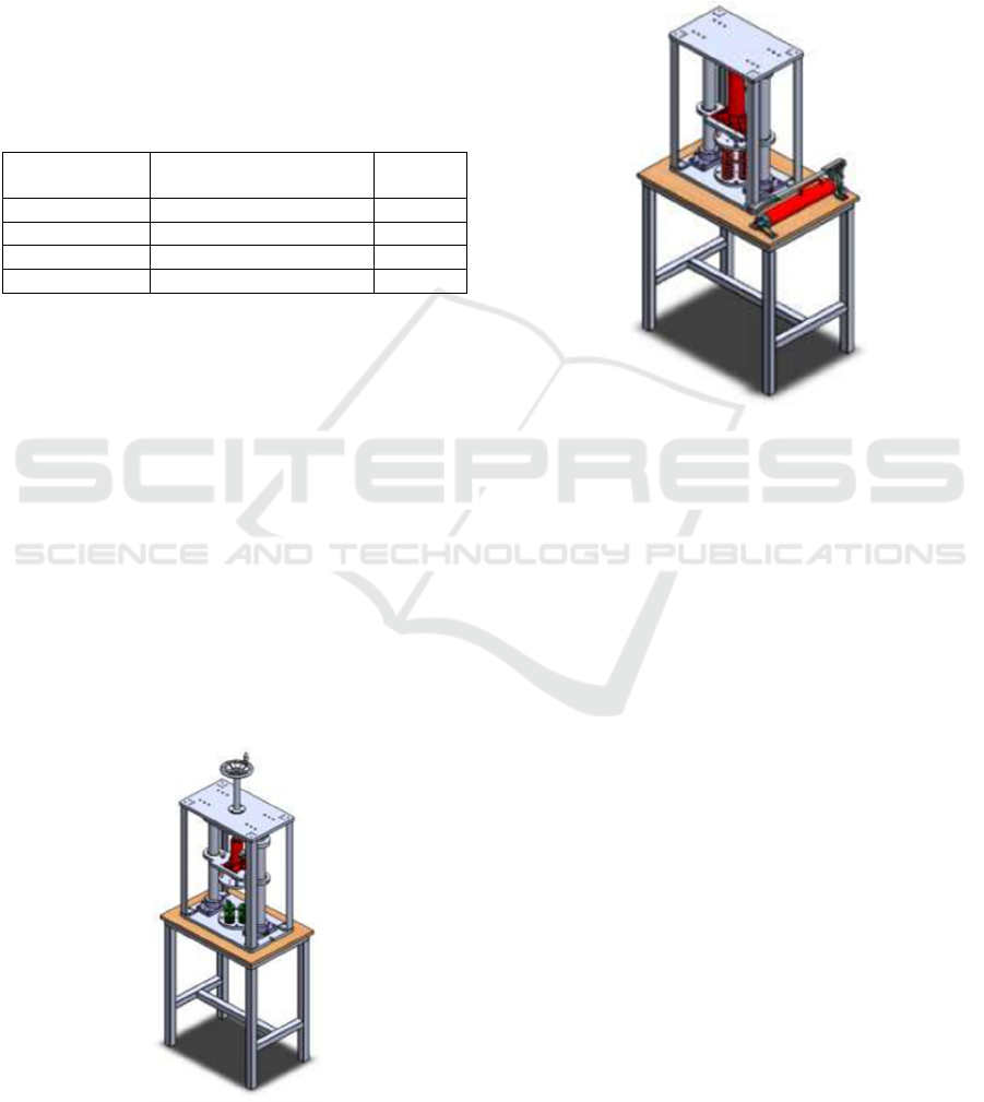
3.1 Design Alternative
Based on the stages in the design, the obtained two
alternative designs of tools for testing the elasticity
properties of the compressed spring with the method
of reading the value of the force variable and spring
constant through a load cell and a millimeter scale.
The form of 3D models for these two alternatives can
be seen in Figure 1 and Figure 2. These two
alternatives can accommodate the integrity or
requirements must be as a spring elasticity testing
tool. Each alternative has advantages and
disadvantages.
Figure 1: 3D Alternative Model 1.
The advantage of the first alternative design is that
the tool operating system is easier. Because the
moving side process can be adjusted by adjusting the
height (adjustable). The operation process is also
facilitated by the presence of a handle wheel. Another
advantage is the relatively smaller dimensions of the
tool. However, the first alternative has a drawback,
namely, the number of components used is more.
Figure 2: 3D Alternative Model 2.
The second alternative design is the opposite of
the first alternative design. These two alternative
designs can accommodate the needs and requirements
as a tool for testing the elasticity of the compressed
spring.
Based on the consideration of the two alternative
designs for testing the elasticity properties of the
compressed spring using the method of reading the
value of the force variable and spring constant
through a load cell and a millimeter scale, the design
chosen is the first alternative design because of the
ease of operation and smaller dimensions of the tool.
The framework used in the first alternative is the L
profile and is used as a reference in calculation and
simulation analysis using Solidworks software.
3.2 Design Calculation
The calculation was carried out on the chosen
alternative design, namely the first alternative which
can be seen in Figure 1. The critical parts that need to
be analyzed and simulated are the frame and upper
plate because they get greater pressure during
operation. The safety factor used in the calculation is
2. This is because this tool was included in the
category of dynamic loading, known materials, and
environmental conditions of fixed and easily
Design of Tool Elasticity of Compressed Springs Tester with the Variable Value of the Force and Spring Constant Through a Load Cell and a
Millimeter Scale Reading Method
939

determined loads and stresses. The simulation results
using Solidworks can be seen in Figures 3 and Figure
4.
Table 2: Pressure Calculation Results
Plane Pressure Value Unit
Frame 0.02 N/mm
2
Upper Plate 2.67 N/mm
2
Figure 3: Frame Simulation Results.
Figure 4: Upper Plate Simulation Results.
From the results of calculations and analysis, the
frame used is recommended to be replaced the
minimize damage that occurs. The recommended
frame profile is using a square tube profile. Based on
the calculation results and recommendations, the
finalization of the design was carried out by changing
the L profile to a square tube profile which can be
seen in Figure 5. While the working drawing without
a framework that will be used as a reference in
making the product can be seen in Figure 6. The part
descriptions can be seen in Table 3.
Figure 5: 3D Final Model.
Figure 6: Final Drawing.
Table 3: Drawing Part.
No. Part Name
1Frame
2 Guide Shaft
3 Indexing Plate
4H
y
draulic Base Plate
5 Base S
p
rin
g
U
pp
e
r
6 Base S
p
rin
g
Lowe
r
7SringHolder Uppe
r
8 Spring Holder Lowe
r
9 Extension Shaft
10 Ad
j
uster Shaft
11 Screw Bush Ad
j
uster Shaft
12 Adjuster Shaft Holde
r
13 Insert Bush Hydraulic Base
14 Hydraulic
15 Load Cell
16 Guide Pin
17 Stri
pp
er Bolt
18 Lifting Eye Bolt
19 Guide Shaft Holde
r
20 Handle Wheel
21 L-Bolt M12x40
22 L-Bolt M8x25
23 L-Bolt M6x16
24 Pin Bolt M8x10
25 Silinder Pin dia 10x35
26 Silinder Pin dia 6x20
iCAST-ES 2022 - International Conference on Applied Science and Technology on Engineering Science
940

4 CONCLUSIONS
A tool for testing the elastic properties of compressed
springs using the method of reading the value of the
force variable and spring constant through a load cell
and a millimeter scale, consisting of the frame and
base, and the system. The use of a hydraulic jack as a
spring press. When the spring is pressed, the length of
the spring will change. This process continues until
the maximum working condition of the spring.
Changes in the length of the spring will be read on the
millimeter scale measuring instrument. Meanwhile,
elasticity is measured with a load cell. Tests were
carried out for a maximum of four springs, with a total
load that can be accommodated 180 kg.
The results of calculations and simulations using
Solidworks software show that the frame and base are
safe because they can withstand a safety factor of 2.
However, it is recommended to use square tube
profile steel. However, this still needs further research
to compare in terms of costs.Words like “is”, “or”,
“then”, etc. should not be capitalized unless they are
the first word of the subtitle.
ACKNOWLEDGEMENTS
Thank you to those who have helped to carry out the
analysis, especially to Politeknik Manufatur Bandung
with this collaboration. And thank you to Politeknik
Negeri Indramayu for financing this research so that
it can be implemented well. We hope that paper can
be used for knowledge and study in vocational
university to improve the students sklills.Please note
that the name of each author must start with its first
name.
REFERENCES
Bhandari, V.B. (1994). Design of Machine Elements. India:
Tata McGraw-Hill International Book Company.
Boljanovic, Vukota. 2004. Sheet Metal Forming Processes
and Die Design. United States: Industrial Press
Budiarto. (2001). Press Tool 3 (Proses Drawing). Bandung:
Politeknik Manufaktur Negeri Bandung.
Budynas dan Nisbett. (2006). Mechanical Engineering.
United States of America: Mc-Graw-Hill International
Book Company.
Deutschman, A. (1975). Machine Design Theory and
Practice. New York: Macmillan
Dharmika, P. Adhi. 2013. Rancang Bangun Load Cell
(Sensor Gaya) Berkapasitas 10 kN untuk Uji Tekan
Material. Jurusan Studi Fisika, FST, UIN.
Djaja, Y., & Hatuwe, M.R (2015). Uji “Ketahanan Lelah
Dan Penurunan Gaya Pegas “Katup Kompresi Akibat
“Beban Operasi” Pada Katup Motor Diesel Output
Rated 400 Kw.11(02), 205–212
Hayes, M. (2006). Compression Spring Equipment, Design,
and Non-Axial Performance. Springs, 45(4), 63-64.
Idiar. 2016. Rancang Bangun Cetakan Deep Drawing Cup
Silindris untuk Selongsong Peluru Kaliber 20
Milimeter. Jurusan Teknik Mesin FTI ITS.
Jadhav, A. R., Pol, G. J., & Desai, A. A. S (2015). Design
and Manufacturing of Hydraulic Spring Stiffness
Testing Machine. 4395 (October 2014), 184–190.
Khurmi RS Gupta, JK., (2005). TextBook of Machine
Design Eurasia, Publising House ltd Ram Nagar, New
Delhi.
Manullang. (2020). Analisa Gaya Tekan Mesin
Pembentukan Logam Pada Pembuatan Tutup Mangkok
Dengan Bahan Aluminium Menggunakan Instrumen
Load Cell. Jurusan Teknik Mesin, FTI, UMSU.
Martias, H. D. (2018). Perancangan Dan Pembuatan Alat
Uji Defleksi Pegas Spiral. 1, 1–7.
Muller, I. Brito, R.M.d, Pereira, & Brusamarello, V. (2010).
Load Cells in Force Sensing Analysis – Theory and a
Novel Application. IEEE. Instrumentation &
Measurement Magazine
Naik, S., & Kumbhalkar, S. B. J. S. S. (2018). Design &
Analysis of Helical Spring Testing Machin: A Review.
6(01), 1059–1060.
Pahl, G., Beitz, W., Feldhusen, J. and Grote, KH.,
Engineering design – a systematic approach, Translated
and Edited by Wallace, K., Blessing, L., 3rd ed (2007),
pp. 125-436, Springer-Verlag, London
Pollack, Herman W. 1988. Tool Design Second Edition.
United States: Prentice Hall
Pratama, Zizka Moch dan Fitri, M. (2021). Desain
Komponen Utama Alat Uji Konstanta Pegas Untuk
Kapasitas 50 N/mm. Jurnal Teknik Mesin, Vol.10. No.1
Publishing Co., IncWidhi Artha, Gandhi. (2015).
Perancangan Die Set untuk Proses Ironing Selongsong
Peluru Kaliber 20 Milimeter. Jurusan Teknik Mesin
FTI ITS.
Setiahardja, T.S. (2010). Pengembangan Alat Ukur
Berbasis Load Cell Untuk Pengujian Tahanan Model
Kendaraan Tempur Amphibi. Jurnal Wave. Vol 4 (02),
66–70
Sularso, Kiyokatsu Suga, (2004). ”Dasar Perencanaan dan
Pemilihan Elemen Mesin”. Jakarta: Pradya Paramita
Togotorop. 2017. Rancang Bangun Alat Ukur Konstanta
Pegas Menggunakan Arduino Uno Dan Sensor
Ultrasonik Hc-Sr04. Jurusan Teknik Eelektro, FT,
UMA.
Yakin, Y. A., Pratiwi, D. S., & Bilaldy, B. F. (2020).
Analisis Konstanta Pegas pada Fondasi Tiang (Studi
Kasus: Gedung Type B DPRD Surabaya). Jurusan
Teknik Sipil Itenas, 42-53.
Yuliafif, Afrizal (2017). Rancang Bangun Cup Ejector Pada
Proses Deep Drawing Cup Selongsong Peluru Kaliber
20 Mm. Jurusan Teknik Mesin FTI ITS.
Design of Tool Elasticity of Compressed Springs Tester with the Variable Value of the Force and Spring Constant Through a Load Cell and a
Millimeter Scale Reading Method
941
