
INSIDE: Semantic Interoperability in Engineering Data Integration
Vitor Pinheiro de Almeida
1 a
, J
´
ulio Gonc¸alves Campos
1 b
, Elvismary Molina de Armas
1 c
,
Geiza Maria Hamazaki da Silva
2 d
, Hugo Neves
1 e
, Eduardo Thadeu Leite Corseuil
1 f
and Fernando Rodrigues Gonzalez
3 g
1
Instituto Tecgraf, Pontif
´
ıcia Universidade Cat
´
olica do Rio de Janeiro (PUC-RIO), Brazil
2
Universidade Federal Do Estado Do Rio De Janeiro (UNIRIO), Brazil
3
Petrobras S.A., Rio de Janeiro, Brazil
Keywords:
Data Integration, Semantic Web, Information Systems, Semantic Interoperability.
Abstract:
One of the critical problems in the industry is data integration. Data is generated continuously and on a large
scale and is persisted using different formats, software, and terminologies. Integrating multiple databases
belonging to different information systems can provide a unified data view and a better understanding of
the data. With that in mind, this paper present INSIDE, a system that enables Semantic Interoperability for
Engineering Data Integration. INSIDE represents queries to one or multiple databases through the concept of
data services, where each service is defined using an ontology. Data services can conceptually represent the
commitments and claims between service providers (databases) and service customers (users) along with the
service lifecycle (the process of querying, integrating, and delivering data). The contributions of this paper are
the following: (1) Use of formal mechanisms for semantic data representation with the connection with the
international community; (2) A conceptual model for a distributed system based on ontologies for querying
and manipulating data from multiple data sources; (3) An implementation of this model, called INSIDE,
developed on top of Apache Spark; and (4) An experimental evaluation of the service composition strategy of
INSIDE for data integration of multiple data sources using a real-world scenario.
1 INTRODUCTION
Data is the most valuable asset for any organization.
However, as much as it is needed for making impor-
tant business decisions, most organizations still lack
a coherent and efficient approach to data integration.
In the context of the oil and gas industry, the scenario
is similar(Atle Gulla., 2008). Data integration in this
area presents problems with the following character-
istics: (1) Dynamic data with varying levels of detail
because engineering systems are constantly changing
and have a lifecycle of more than 40 years; (2) Need
for scalable solutions for big data. An approach to
a
https://orcid.org/0000-0002-6544-9541
b
https://orcid.org/0000-0002-5023-3836
c
https://orcid.org/0000-0002-0606-5994
d
https://orcid.org/0000-0001-7554-2611
e
https://orcid.org/0000-0001-6834-2654
f
https://orcid.org/0000-0002-7543-4140
g
https://orcid.org/0000-0002-7440-9509
data integration for oil and gas needs to be scalable,
knowing how to handle large volumes of data and pro-
duce results in acceptable times; (3) Lack of knowl-
edge of the system’s native query language to explore
data from databases. This requirement addresses the
importance of providing an interface to interact with
the integrated data for users who do not know how
to formulate database queries; and (4) Assistance of
a system specialist in database mapping. This task,
in most cases, requires the knowledge of a domain
expert. Thus, for an oil and gas data integration ap-
proach, it is necessary to provide a way to make it
easier for the user to map schemas.
With that in mind, the Semantic Interoperability
for Engineering Data Integration (INSIDE) project
is presented. INSIDE enables the representation of
queries for one or multiple databases through the con-
cept of data services, where each service is defined us-
ing an ontology. Data services can conceptually rep-
resent the commitments and claims between service
providers (databases) and service customers (users)
Almeida, V., Campos, J., Molina de Armas, E., Hamazaki da Silva, G., Neves, H., Corseuil, E. and Gonzalez, F.
INSIDE: Semantic Interoperability in Engineering Data Integration.
DOI: 10.5220/0011748700003467
In Proceedings of the 25th International Conference on Enterprise Information Systems (ICEIS 2023) - Volume 1, pages 107-114
ISBN: 978-989-758-648-4; ISSN: 2184-4992
Copyright
c
2023 by SCITEPRESS – Science and Technology Publications, Lda. Under CC license (CC BY-NC-ND 4.0)
107

along with the service lifecycle (the process of query-
ing, integrating, and delivering the data). Data inte-
gration is enabled through service composition so that
more complex queries can be created using smaller
ones. The contributions of this work are the follow-
ing: (1) Connection with the international community
to apply state of the art in the modeling and represen-
tation of engineering data from industrial plants; (2)
Use of formal mechanisms for data semantic repre-
sentation, taking into account the developing of mul-
tiple ontologies to support the INSIDE execution; (3)
A conceptual model for a distributed system based on
ontologies for querying and manipulating data from
multiple data sources: (4) An implementation of this
model, called INSIDE, developed on top of Apache
Spark (an open-source, distributed processing system
used for big data workloads); and (5) An experimen-
tal evaluation of INSIDE using a real-world scenario.
Experiments show the pros and cons of using the ser-
vice composition strategy for data integration of mul-
tiple data sources.
2 BACKGROUND
An ontology is a set of statements describing the con-
cepts and relations of a particular domain (Pease,
2011). Ontologies are expressed in ontology lan-
guages, such as RDFS (Brickley and Guha, 2014)
and OWL (W3C-OWL-WG-2012, 2012; Antoniou
and van Harmelen, 2009), and are encoded in RDF.
For our purposes, a knowledge base (KB)(Sakr et al.,
2018) is a set of statements (triples) possibly describ-
ing ontologies. Interoperability is defined by IEEE as
”the ability of two or more systems or components to
exchange information and be able to use the informa-
tion exchanged.”(Geraci et al., 1991). For a system
to use information from another system, it is impor-
tant to highlight the challenges that this can involve
(Ziegler and Dittrich, 2004). Every data integration
problem is unique. While the goal is always to pro-
vide a homogeneous, unified view of data from dif-
ferent sources, the particular integration task may de-
pend on several factors: (1) Some systems use dy-
namically generated data that is not persisted in its
database. It only deviated from persisted data; (2)
The intended use of the data integration. For exam-
ple, if it requires write access or ready only access;
(3) The type of information that is managed by the
systems (alphanumeric data, multimedia data, struc-
tured, semi-structured or unstructured data); (4) Se-
mantic heterogeneity, where an attribute of the same
name has different meanings in different systems. For
example, some databases can persist the telephone
number using the regional code, and some do not; (5)
Databases can have static information (data that does
not change over time) or dynamic information (data
that changes over time).
Tolk at el. proposed the LCIM (Levels of Con-
ceptual Interoperability Model) (Tolk and Muguira,
2003), which has seven levels of interoperability, to
consider the interoperability problem as more than
just a technical problem but a conceptual one. The
following are a brief description of the LCIM lev-
els. The Level 0 states no connection between sys-
tems, Level 1 (Technical) represent systems that pro-
duce and consume data from each other but only us-
ing network communication protocols such as HTTP,
TCP/IP. Level 2 (Syntactic interoperability) defines
data structure but without describing the meaning, for
example, using XML. Levels higher than 3 (Seman-
tics interoperability) have data semantics in addition
to the well-defined syntactic. Those systems execute
data exchanges between systems with a common data
reference model, such as dictionaries and glossaries.
Level 4, Pragmatic interoperability, includes systems
that, in addition to the joint agreement on the meaning
of the data, understand the data flow in each system,
allowing extracting the context of each data. Level
5, Dynamic interoperability, is characterized by sys-
tems that both can change the data flow and allow
the change in this flow to propagate to the other sys-
tems. Lastly, level 6, Conceptual interoperability, is
implemented by systems that share the same concep-
tual understanding (thus transparently exposing their
information, processes, states, and operations).
2.1 Use Case Description
The equipment’s specification is one of the most crit-
ical engineering tasks. To validate the functionality
and safety of the equipment, it must accomplish some
standards and norms. Our case study focuses on veri-
fying which pressure vessel equipment accomplishes
the brazilian norm NR-13
1
, and what is their NR-13
fluid category. The NR-13 fluid category is calculated
using the type of fluid of the pressure vessel. In or-
der to determine if a pressure vessel is NR-13 or not,
it is necessary to access different data sources: (1)
the SmartPlant P&ID (SPPID)
2
relational database,
which contains data of all pressure vessels that need to
be checked; and (2) a spreadsheet with the Data Sheet
(in Excel format), which contains the specific data
related to NR-13 and descriptions about each pres-
sure vessel. Using the TAG, the attribute that identi-
1
NR-13: https://www.braziliannr.com/brazilian-regulat
ory-standards/nr13-boilers-and-pressure-vessels/
2
SPPID: https://smartprocessdesign.com/tag/sppid/
ICEIS 2023 - 25th International Conference on Enterprise Information Systems
108
fies each pressure vessel, the system can integrate the
data from the relational database and the spreadsheet
related to each pressure vessel, calculate the NR-13
fluid category of each pressure vessel and finally test
whether or not it is following the NR-13 standard.
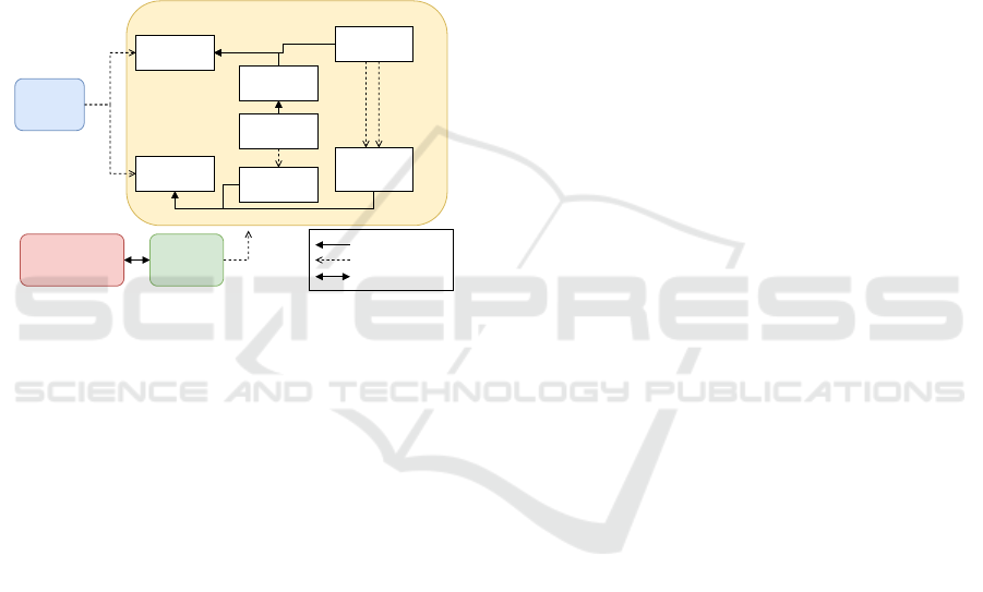
3 KNOWLEDGE BASE
The data model developed for our case study contains
three ontologies (the domain, the service (UFOS-S)
and the data source ontology) and one taxonomy. Fig-
ure 1 shows all ontologies and the taxonomy interact.
Data Source Ontology
queryDataSource
accessDataIn
Service
Ontology
DataSource
DataSource
Components
hasAttribute
DataSheet
DataSheet
Components
Spreadsheet
disjoint
hasTable hasPrimaryKey
Relational
Database
Relational
Database
Components
disjoint
isAssociatedWith
Vocable
Taxonomy
ISO15926 - Part 14
Domain Ontology
subclass
relationship
common concepts
Figure 1: INSIDE Knowledge Base ontologies and taxon-
omy.
The Domain Ontology presents concepts and re-
lations well structured to enable the representation
of the oil and gas industry information and to en-
sure quality for its conceptual models. It uses the
ISO15926 part 14 as upper ontology and describe
concepts related to the commissioning project phase
of an industrial plant within Petrobras company. The
Data Source Ontology describes data sources, all their
structure, and elements, independently of the data
source type. The Vocable Taxonomy defines a set of
terms that complements the domain ontology to map
elements of each data source enabling the represen-
tation of our use case vocabulary. Lastly, the Service
Ontology extends the UFO-S(Nardi et al., 2015) ser-
vice ontology core to describes all basic and compos-
ite data services that INSIDE clients can execute. Ba-
sic services are small queries to one data source, cre-
ated to be combined with other basic services to cre-
ate more complex queries. The service that combines
data services is called composite service. The Service
ontology specializes the basic services in DataSer-
vices, which are simple queries that can be executed
on a data source; Filter, which are services that fil-
ter the data following some predetermined rule; and
RuleComputation which are services that applies a
predetermined rule to a data service result set; while
the composed services are classified in AuxiliarSer-
vice, which are internal and non executable data ser-
vices and DataProcessService that represents all com-
posite services that the client can execute.
The DataService class have two different sub-
classes, the RelationalDataBaseAccessService which
models how to access data on relational databases and
SpreadsheetAccessService, that represents how to ac-
cess data on a Spreadsheet. The Data Source ontol-
ogy contains specific information about each table, in-
cluding all their columns, primary and foreign keys,
and the column type and description. Moreover, each
column is mapped to our Vocable Taxonomy and the
ISO15926 upper ontology, giving semantic meaning
to every column. The main idea of the service com-
position strategy is to compose smaller services to
achieve more complex services that represent more
complex queries. INSIDE can integrate data from dif-
ferent sources to answer queries by composing data
services. Next section, we explain the conceptual
model of our architecture and how each component
of INSIDE interacts with each others.
4 SYSTEM MODEL
We now present the conceptual architecture of IN-
SIDE, which enables semantic interoperability among
distributed and heterogeneous data sources. The in-
frastructure is built up from three main components:
Front-End, KB Manager, and Engine (see Figura2).
In an instantiation of the infrastructure, multiple in-
stances of the Front-End, KB Manager and Engine
can occur. The instances execute independently and
asynchronously with each other and can run on dif-
ferent machines. The Engine communicates through
the publish-subscribe paradigm(Eugster et al., 2003)
with the Front-End, and the KB Manager communi-
cates using HTTP Rest. The internal structure of each
of the three components is described in the following
subsections.
4.1 Front-End
The INSIDE Front-End is a web application that pro-
vides an interface to enable communication between
the user and the INSIDE system. Using the Front-
End, the user can execute any data service or create
new composite services. The user can only create
new composite services that use the existing data ser-
vices on the INSIDE service ontology. In other words,
the user cannot create new basic services through the
Front-End, and it is only possible to create new com-
INSIDE: Semantic Interoperability in Engineering Data Integration
109
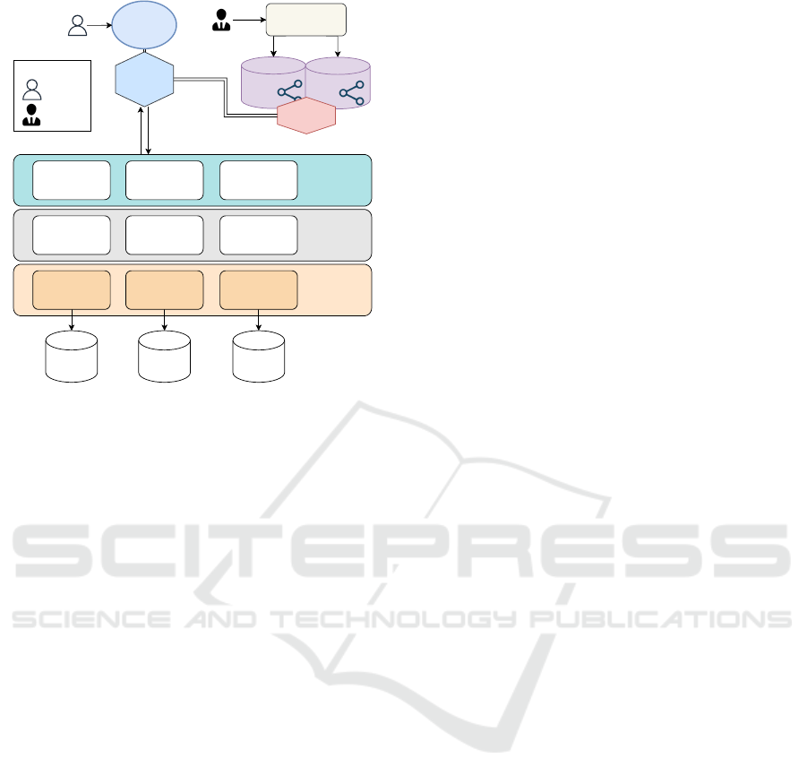
Data access
Data source /
Data model 1
Data model 1
query executor
Data model n
query executor
Data model 2
query executor
Data Manipulation
Query Orchestrator
Query reader and
result parser
Query decomposition
Result filtering and
processing
Query storage
Communication
module
Data source /
Data model 2
Data source /
Data model n
KB: Domain
Ontology
Ontology & Mapping
management
KB: Services
Ontology
KB manager
Legend:
Final User
Ontology
Engineer
Aplication
FrontEnd
Browser
BackEnd
Query
result
INSIDE query
Query result
aggregator
...
Figure 2: An instance of the proposed infrastructure.
posite services using the ones that are already created.
Besides query execution and creation, the Front-End
is also responsible for enabling communication be-
tween the Engine and the KB Manager. From the IN-
SIDE query execution point of view, the Front-End is
the entry point where the user can select and run data
services. To execute a data service, the Front-End
sends to the KB Manager which data service must be
executed. The KB Manager is responsible for gen-
erating the queries to all target data sources and de-
scribing all data manipulations that must be executed
to generate the data service results. We call this com-
plete query description INSIDE query, a query written
in a language that the Engine can understand and ex-
ecute. Thus, the INSIDE query can describe queries
that must be made to multiple data sources, describ-
ing how data of each data source will be joined and
the data manipulations and filters that must be applied
to the result dataset.
4.2 KB Manager
The KB Manager’s main objective is to generate the
INSIDE query, which can execute a specific data ser-
vice. The data services, as explained in section 3, con-
tains all details about the query, target data sources,
mappings, how to join data from different sources, fil-
ters, and rule computations. Each basic service has
an associated query written in its native language,
and all native queries related to all basic services
are persisted on the KB Manager’s auxiliary reposi-
tory. Moreover, all rule computations and filters are
also persisted on the KB Manager’s auxiliary reposi-
tory. On data service execution time, all those native
queries related to the basic services associated with
the data service being executed are added to the IN-
SIDE query. In addition to the INSIDE query genera-
tion, the KB Manager’s logic layer also contains algo-
rithms responsible for persisting a new composite ser-
vice to the INSIDE knowledge base. The functional-
ity of creating new composite services does not allow
the creation of basic services, filters, or rule computa-
tions; these must be created manually directly on the
ontology. The Communication with INSIDE Front-
End module provides functions available through the
web that the Front-End can use to access the KB Man-
ager functions. Finally, the Data Access layer pro-
vides access to both the auxiliary repository and the
knowledge base, where all ontologies are persisted.
4.3 Engine
The Engine is the system responsible for executing
the INSIDE query and sends the query results to the
Front-End. The Engine system model is organized
into three layers. The upper layer is the Query Or-
chestrator layer, which encapsulates three modules.
The first is the communication with all other INSIDE
components through the publish-subscribe paradigm.
The second is the query storage, which register every
INSIDE query received for internal control and log-
ging purposes. And finally the query reader and re-
sult parser, responsible for deserializing all received
INSIDE queries, starting their execution, serializing
all query results, and sending them to the Communi-
cation module. The second layer is the Data Manip-
ulation, which is composite of three modules: Query
decomposition, Query result aggregator, and Result
filtering and processing. The Query decomposition
module separates each sub-query contained in the IN-
SIDE query and sends them to be executed on their
respective data sources. The Query result aggregator
is responsible for combining the answers of each sub-
query to create a final answer for the INSIDE query.
Finally, the Result filtering and processing module
contains a set of functions capable of applying filters
and computations to datasets. Filters and computa-
tions can be applied to datasets after or before joining
them with other datasets. While filters can reduce the
dataset size, rule computations are calculations exe-
cuted upon the dataset to generate new columns. Both
filters and computations are described on the INSIDE
query. The last layer is the Data access, which is re-
sponsible for accessing data on each data source con-
nected to INSIDE. This layer contains different data
connectors to each data source, enabling queries to be
executed.
ICEIS 2023 - 25th International Conference on Enterprise Information Systems
110

5 IMPLEMENTATION
The INSIDE implementation is designed to query
data from both a relational database and equipment
data sheets in the form of Excel spreadsheets. All
communication made by the INSIDE Engine with
other INSIDE components is done using Apache
Kafka
3
through the use of two different APIs: Pro-
ducer API and Consumer API. Both APIs use the con-
cept of Kafka Topics, which are a logical category of
messages; they represent a stream of the same data
type. In order to receive a specific type of stream,
a data stream Kafka consumer must subscribe to the
topic in which the data stream is being published. Ev-
ery Kafka topic in INSIDE is related to a specific type
of INSIDE query in a way that all INSIDE queries that
represent the same data service have their answers
sent to the same Kafka topic. The Kafka topic also
works as a database that can persist data for a certain
period of time.
5.1 Engine
The INSIDE Engine was implemented in Java lan-
guage composed by four layers. The first layer corre-
sponds to the communication infrastructure between
the INSIDE Engine and the Front-End built using
Apache Kafka. All submitted queries are published
by the Front-End to the Orchestrator Input topic, and
each one is executed in the order of arrival. Each
query received by layer 2 (Orchestrator) is executed
in a new thread created only for the execution of
the query. This way, it is possible to run multiple
queries simultaneously in parallel. The Communi-
cation module is subscribed to the Orchestrator In-
put topic, where all INSIDE queries are published.
Every query received is registered in a file for log-
ging purposes by the Query Storage module. After
the INSIDE query is executed by layers 3 and 4, the
query response is published using the Spark Stream-
ing connector for Kafka. Layer 3 (Data Manipu-
lation) is implemented with Apache Spark and per-
forms operations between dataframes, such as joins,
filters, aggregations, and even more complex process-
ing, such as generating new data from the data of one
or more dataframes. Each module of layer 3 can inter-
pret a subquery and its data manipulation details and
know how to execute each data manipulation using
Apache Spark. Finally, layer 4 receives each subpart
of the INSIDE queries that contain a specific query
that must be executed on a data source. There are two
different data access modules implemented, the JDBC
access module and the Excel access module.
3
Apache Kafka: https://kafka.apache.org
5.2 Front-End
The client side of INSIDE Front-End was devel-
oped in JavaScript using Vue.js - a JavaScript frame-
work for developing user interfaces for web applica-
tions. We used an open-source library for creating
flowcharts, to develop the interface that allows the
user to create new composite services as block com-
position. When the user saves the new composite
service, its data is sent to the KB Manager and per-
sisted to the Ontologies. When the user executes a
data service through the browser, the back-end (de-
veloped in Node.js) requests the INSIDE query asso-
ciated with that data service. It communicates with
the KB Manager using HTTP REST and with the En-
gine using Apache KafkaJS. After requesting the IN-
SIDE query, the Front-End receives and sends it to
the INSIDE Engine using KafkaJS to execute it. Af-
ter executing the INSIDE query, the Engine returns
its results to the Kafka topic to enable KafkaJS to re-
trieve them. Finally, on the client side, Socket.IO was
used, a JavaScript library allowing real-time commu-
nication between the browser and the server.
5.3 KB Manager
The KB manager is a web application, developed in
Python language with the Flask framework, that pro-
vide web services to manage the access and manipula-
tion of the facts that are saved in the knowledge base.
The data access layer is implemented using two main
python libraries: (A) SPARQLWrapper, which is used
to execute SPARQL queries on the ISO15926 public
endpoint; (B) the AllegroGraph Python API, which
provides methods that enables querying the ontolo-
gies stored on AllegroGraph. AllegroGraph
4
is the
triplestore in which all the INSIDE ontologies are per-
sisted, it runs on a Docker container, and it is accessed
by a SPARQL endpoint. The Logic layer of KB Man-
ager contains all functions responsible for generating
the INSIDE query associated with a specific data ser-
vice.
6 EXPERIMENTS
6.1 Setup
We used two data sources for the experiments, one
set of pressure vessel datasheets in are Excel spread-
sheets format, and one relational database, which is
4
AllegroGraph: https://allegrograph.com/
INSIDE: Semantic Interoperability in Engineering Data Integration
111

used by the Intergraph SmartPlant P&ID (SPPID soft-
ware) in Oracle Database 11g Enterprise Edition Re-
lease 11.2.0.3.0 - 64bit Production. The total size of
our SPPID database is 96,19 GB, and it contains in-
formation about a real-world oil platform. The pres-
sure vessel datasheets are total of 27, each one con-
taining information about a single pressure vessel.
For all experiments, we executed all three INSIDE
components on a computer with a Quad-Core Intel I7
CPU with 2.7GHz and 16GB of RAM. As our SPPID
relational database contains sensitive information, we
access the relational database through the internet on
all our tests using a VPN. For the communication in-
frastructure, we used Apache Kafka version 2.0 and
Zookeeper. Moreover, we used the Allegro triplestore
as our SPARQL endpoint to access all INSIDE on-
tologies.
6.2 Evaluating Basic Services
The first experiment is focused on evaluating the pro-
cessing time of all basic services developed for our
use case. They are used in a composite service to im-
plement our final use case query. There are a total
of 14 basic services, 13 are basic services that access
the SPPID relational database, and one is a basic ser-
vice that accesses a set of pressure vessel datasheets,
which are Excel spreadsheets. The execution time
showed in the column INSIDE Engine on Table 1 be-
gins when the INSIDE Engine receives the JSON file
that describes the INSIDE-query and ends when all
results are posted to the Kafka topic that the Front-
End is subscribed to receive the query answer. The
column Result Size represents the number of rows ob-
tained from the services, and the column ORACLE
Client is the time elapsed by the Oracle client to exe-
cute the SQL query associated with the basic service
and retrieve all the results (except for the SB27, which
is the only queries spreadsheets).
The time that the INSIDE Engine takes to con-
nect to the database is always around 5,10 seconds.
Since the Oracle Client was already connected to the
database for all our tests, we did not add the database
connection time to the INSIDE Engine column. By
doing so, we can compare the execution of the same
query, one written using our INSIDE-query vocabu-
lary (INSIDE-Engine column) and the other written
directly in SQL (Oracle Client). For all basic services
execution, the time elapsed by the KB Manager and
the Front-End components is much smaller than the
INSIDE-Engine execution time. That is why we do
not show these times on the table. The KB Man-
ager component execution time is always between
0,34 and 0,51 seconds for all basic services, and the
Table 1: Processing time (in seconds) of the basic services
used by the use case query. All processing times are an
average of 20 runs.
Name INSIDE
Engine
ORACLE
Client
Result
Size
SB4 22,90s 9,39s 100000
SB5 0,09s 0,01s 1
SB8 1,16s 0,82s 4368
SB9 0,10s 0,01s 1
SB10 8,13s 2,78s 35259
SB12 0,09s 0,01s 1
SB13 23,43s 14,24s 100000
SB15 24,69s 9,57s 100000
SB16 25,81s 11,48s 100000
SB17 18,27s 11,74s 70886
SB20 1,38s 0,41s 4368
SB22 25,49s 11,12s 100000
SB25 1,64s 0,36s 4368
SB27 116,09s - 27
Front-End adds a 10 ms delay to send the INSIDE-
query to the INSIDE Engine. The KB Manager per-
formance also shows that the time elapsed to generate
the INSIDE-query (JSON file) using the ontologies
(on the KB Manager) does not add much overhead
to the entire query. Finally, the results show that the
INSIDE Engine processing time is acceptable when
compared to the processing time to execute the SQL
query and retrieve all results (Oracle Client column).
6.3 Evaluating Composite Services
The second experiment is focused on evaluating the
processing time of the composite services and how
processing time increase as we add new services to
the INSIDE query. Table 2 summarize the test results.
The first composite service evaluated is service SC1,
which makes an inner join between SB22 and SB20,
selects all columns as output, and posts the results on
the corresponding Kafka topic. The inner join is exe-
cuted in the INSIDE Engine, joining 100.000 records
from service 22 with 4368 records from service 20.
The number of results of SC1 is 4368, and its pro-
cessing time is 154,48 seconds. Second, the SC2 is
a composite service that joins the results of three ba-
sic services: SB20, SB22, and SB25. In summary, it
adds service SB25 to SC1 with an inner join between
SC1 result with service SB25. Thus, SC2 first joins
SB20 with SB22 and then joins its result with service
SB25, and its processing time is 159,322 seconds. Fi-
nally, SC3 is a composite service that adds one more
service to SC2. It adds service SB16 to SC2, making
an inner join between the result of SC2 with service
ICEIS 2023 - 25th International Conference on Enterprise Information Systems
112

SB16. SC3 takes 173,984 seconds to be executed in
the INSIDE engine.
Table 2: Processing time of composite services.
Name Engine Engine Optimized
SC1 154,48s 17,44s
SC2 159,32s 18,23s
SC3 173,98s 16,55s
All basic services are executed in parallel, thus
SC1, SC2 and SC3 takes approximately 26 seconds
to retrieve all data from all basic services. The dif-
ference between the processing time of SC1 and SC2
is 4,84 seconds because it only adds the results of
service SB25, which is only 4368 records. On the
other hand, the difference between SC3 and SC2 is
14,66 seconds, which is higher compared to the in-
crease from SC1 to SC2. This is because SC3 adds
service SB16, which have 100000 results and greatly
increase the size of the data input. The results show
that while the services retrieve a high number of re-
sults, the service composition can greatly increase the
processing time. The third column of table 2 shows
the processing time for the optimized composite ser-
vice version. This optimization is executed by the KB
Manager when all the basic services of a composite
service are targeted to the same relational database.
KB Manager takes all SQL queries and reformulates
them into only one SQL query decreasing the query
processing time.
6.4 Evaluating The Use Case Service
This experiment aims to measure the processing time
of composite service SC14, which represents our real
world use case query. SC14 composite service makes
an inner join between SC13-SPPID and SB27(FD)
and applies a rule computation to the result of this
join which generates a new column to the dataset. A
complex rule computation was applied to the join re-
sult of SC13-SPPID and SB27. It generates ”True”
if the pressure vessel is according to the NR13 stan-
dard, ”False” if not, and ”Undefined” if it is miss-
ing some important data to make the evaluation. Ser-
vice SC13-SPPID is composition of all basic services
listed on table 1 (without the SB27) but applies a fil-
ter to keep in the result dataset only equipment that
are pressure vessels. Table 3 shows the processing
time of each INSIDE component to execute those ser-
vices. The SQL query optimization was possible for
SC13-SPPID, then the INSIDE Engine took 39,25
seconds to execute the INSIDE-query generated by
KB Manager.SB27-FDs is a basic service, but it is re-
quired to read 27 spreadsheets (one for each pressure
vessel) to collect data from each of them. Generat-
ing the SB27-FDs INSIDE-query is quicker, but read-
ing all 27 spreadsheets files, collecting their data, and
putting it together on a united dataset took 116,08 sec-
onds. For SC14, the engine took 135,19 seconds to
execute both SC13-SPPID and SB27-FDs, join their
results, and apply the rule computation to the joined
result to calculate if each pressure vessel is NR13 or
not and post the final dataset to the corresponding
Kafka topic.
Table 3: Processing time of composite services.
Name KB Manager Engine
SC14 20,58s 135,19s
SC13-SPPID 18,58s 39,25s
SB27-FDs 0,48s 116,08s
7 RELATED WORKS
Among the studied solutions in the systematic re-
view of works about data interoperability solutions
in the industry in (Campos et al., 2020), we selected
the more similar works to INSIDE. Dhayne et al.
(Dhayne et al., 2018), classified as level 3 in LCIM
(Semantics level), proposes a semantic solution called
SeDIE to integrate healthcare structured and unstruc-
tured data, based on statistical method and a multi-
criteria decision-making model. It recognizes pat-
terns in HL7 segments to be filled with information
extracted from a free medical text, and converts data
from HL7 messages into RDF, integrating and linking
patient data. The framework SPEDAS (Angelopou-
los and et al., 2019) (Space Physics Environmental
Data Analysis System), also classified as level 3 in
LCIM, is a software development platform supported
by NASA Heliophysics written in Interactive Data
Language (IDL) to support the loading, plotting, an-
alyzing, and integrating of data from various space
and ground observatories. Lastly, Sarabia-Jacome et
al. (Sarabia-J
´
acome et al., 2020), present the Seaport
Data Space (SDS) based on the IDS (Industrial Data
Space) architecture to solve the problem of data in-
teroperability and associated inter-operation between
seaport stakeholders. Additionally to IDS architec-
ture, they propose the integration of a Big Data ar-
chitecture into the SDS environment. Its modules
provide capabilities to extract, clean, and load data,
as such as to store, process, and analyze the shared
data using open-source Big Data platforms and frame-
works such as Apache NiFi, Hadoop, HDFS, Apache
Spark, Apache Kafka, and HBase.
Contrary to the above solutions, the INSIDE clas-
sifies as level 5 in the LCIM model (Dynamic level).
INSIDE: Semantic Interoperability in Engineering Data Integration
113

In addition to describing and representing the data us-
ing domain ontology which gives meaning to all data
mapped to it, INSIDE also models the data flow us-
ing a service ontology. The service ontology allows
the system to understand how the data will flow from
one system to another and not only to give meaning
to each attribute of the connected data sources. The
representation of the data flow between systems is a
positive differential. Also, it enables the INSIDE data
model to identify possible inconsistencies among sets
of services since a service can be defined using an-
other service (composite service).
8 CONCLUSION
This paper presents INSIDE, a system based on on-
tologies that enable semantic interoperability for en-
gineering data. From a practical point of view, for the
oil sector, the study of semantic models contributes
to the definition of the data model to be used, which
is one of the critical points of software development.
In summary, the contributions of this project are: (i)
the proposal of a conceptual model and its implemen-
tation that resulted in the creation of INSIDE, which
uses a composition of services strategy to integrate
multiple heterogeneous data sources; (ii) a prelimi-
nary experiment in which the service composition
technique is evaluated using INSIDE; (iii) a service
ontology, developed for our case study, that describes
all types of queries and interests that a customer has
about a set of different data sources; (iv) a domain tax-
onomy, which encompasses the elements present in
the case study; and (v) proposal of a unique query lan-
guage to query different types of databases. All data
sources connected to INSIDE are mapped to concepts
defined in this taxonomy. This will help engineers
understand the information stored in all mapped data
sources and their components. Also, the query lan-
guage is capable of accessing any data source con-
nected to INSIDE, as well as making it possible to
merge data from these different sources into a result-
ing dataset. The approach was evaluated with the case
study related to the regulatory standard NR-13. The
experiments executed show that the service composi-
tion strategy for database integration helps new de-
velopers to understand the underlying data sources
since the queries and processes of a company are
represented semantically, using the service ontology.
As future works we propose the develop a human-
friendly interface to help engineers create queries to
encapsulate their interests and automatize the genera-
tion of the SQL queries for each basic data service as-
sociated with a relational database. Also, one possible
line of future research is to use international standards
to serialize the data returned from an execution of an
INSIDE query.
REFERENCES
Angelopoulos, V. and et al. (2019). The space physics envi-
ronment data analysis system (spedas). Space Science
Reviews, 215.
Antoniou, G. and van Harmelen, F. (2009). Web ontol-
ogy language: OWL. In Handbook on Ontologies.
Springer.
Atle Gulla., J. (2008). Interoperability in the petroleum in-
dustry. In Proceedings of the Tenth International Con-
ference on Enterprise Information Systems - Volume
4: ICEIS, pages 33–40. INSTICC, SciTePress.
Brickley, D. and Guha, R. (2014). RDF schema 1.1. W3C
recommendation, W3C.
Campos, J., Pinheiro de Almeida, V., Silva, G., Caiado, R.,
Corseuil, E. T., Gonzalez, F., and Pereira, C. (2020).
State of the art on system architectures for data inte-
gration. Rio Oil and Gas Expo and Conference.
Dhayne, H., Kilany, R., Haque, R., and Taher, Y. (2018).
Sedie: A semantic-driven engine for integration of
healthcare data. In 2018 IEEE International Con-
ference on Bioinformatics and Biomedicine (BIBM),
pages 617–622, Los Alamitos, CA, USA. IEEE Com-
puter Society.
Eugster, P. T., Felber, P. A., Guerraoui, R., and Kermarrec,
A.-M. (2003). The many faces of publish/subscribe.
ACM Comput. Surv., 35(2).
Geraci, A., Katki, F., McMonegal, L., Meyer, B., Lane,
J., Wilson, P., Radatz, J., Yee, M., Porteous, H., and
Springsteel, F. (1991). IEEE Standard Computer Dic-
tionary: Compilation of IEEE Standard Computer
Glossaries. IEEE Press.
Nardi, J. C., de Almeida Falbo, R., Almeida, J. P. A., Guiz-
zardi, G., Pires, L. F., van Sinderen, M. J., Guarino,
N., and Fonseca, C. M. (2015). A commitment-based
reference ontology for services. Information Systems,
54:263–288.
Pease, A. (2011). Ontology: A Practical Guide. Articulate
Software Press.
Sakr, S., Wylot, M., Mutharaju, R., Le Phuoc, D., and Fun-
dulaki, I. (2018). Linked data: Storing, querying, and
reasoning. Springer International Publishing.
Sarabia-J
´
acome, D., Palau, C. E., Esteve, M., and Boronat,
F. (2020). Seaport data space for improving logistic
maritime operations. IEEE Access, 8:4372–4382.
Tolk, A. and Muguira, J. (2003). The Levels of Conceptual
Interoperability Model.
W3C-OWL-WG-2012 (2012). OWL 2 web ontology lan-
guage document overview (second edition). W3C rec-
ommendation, W3C.
Ziegler, P. and Dittrich, K. R. (2004). Three decades of data
integration - all problems solved? In IFIP Congress
Topical Sessions.
ICEIS 2023 - 25th International Conference on Enterprise Information Systems
114
