
Development of a Smartphone App for Lane Departure Warning
Nafisa Zarrin Tasnim, Attiq Uz Zaman and M. I. Hayee
Department of Electrical Engineering, University of Minnesota Duluth, Duluth, MN 55812, U.S.A.
Keywords: Smartphone App, Database, GPS, Reference Road Heading, Lane Departure Detection, Algorithms.
Abstract: Unintentional Lane departure is a significant safety risk. Currently, available commercial lane departure
warning systems use vision-based or GPS technology with lane-level resolution. These techniques have their
own performance limitations and are complex and expensive to implement, inhibiting their widespread market
penetration. We have previously developed a lane departure detection (LDD) algorithm using standard GPS
technology. Our algorithm acquires the trajectory of a moving vehicle in real-time from a standard GPS
receiver and compares it with a road reference heading (RRH) to detect any potential lane departure. The
necessary RRH is obtained from one or more past trajectories on that road using our previously developed
RRH generation algorithm. Our previous field tests have shown that our lane departure detection and warning
technique is robust enough to detect unintentional lane departures successfully. Due to its robustness and
simplicity, we have now developed a smartphone app for this technique incorporating our previously
developed LDD and RRH generation algorithms to detect a lane departure and issue a warning to the driver
in real-time using an audible alarm. We have developed the app database structure and have completed
programming the algorithms for the app. We are currently in the testing phase. The smartphone app is being
prepared for both iOS and Android phones, however, the Android app will be available before the iOS app.
1 INTRODUCTION
Modern vehicles include Advanced Driver
Assistance Systems (ADASs) because they play a
vital role in safe driving (Maag et al., 2012). Lane
departure warning is one of the primary ADAS
features to prevent accidents on highways and
freeways if a vehicle unintentionally departs from its
lane. According to the American Association of State
Highway and Transportation Officials (AASHTO),
almost 60% of fatal accidents happen due to an
unintentional lane departure of a vehicle on crucial
roads (Officials, 2008). A recent study that compared
crashes with and without a lane departure warning
system (LDWS) revealed that an in-vehicle LDWS
helped reduce crashes of all severities by 18%,
injuries by 24%, and fatalities by 86% without
considering driver demographics (Cicchino, 2018).
Most lane departure warning systems either use a
single camera and a processor (Hsiao & Yeh, 2006)
(An et al., 2006) (Yu et al., 2008) (Leng & Chen,
2010) or optical scanning and Light Detection and
Ranging (LIDAR) sensors (Lindner et al., 2009) to
identify the impending lane departure. The camera-
based systems employ different image processing
techniques like the linear parabolic lane model (Jung
& Kleber, 2004) or the extended edge-linking
algorithm (Lin et al., 2010) to extract the lane
markings from successive picture frames to calculate
the lateral shift of the vehicle. Camera-based systems
need favorable lighting conditions to recognize the
lane markings at night. However, recent
advancements in image processing techniques during
the past couple of decades conquered the limitation of
diminished lighting conditions to successfully detect
lane departure even in low lighting or night-time
(Hsiao et al., 2008). A Video-Based Lane Estimation
and Tracking (VioLET) system with steerable filters
can detect solid-line and segmented-line markings
under different lighting and road conditions leading
to robust and accurate lane-marking detection
(McCall & Trivedi, 2006). Likewise, optical scanning
systems consisting of a linear array of infrared
transmitting devices can scan the lateral area of the
highway for lane markings even in varying lighting
conditions (Dobler et al., 2000). The performance of
the camera and optical sensor-based systems in
detecting lane departure deteriorates when the road
conditions are unfavorable due to an irregular,
broken, or absence of lane markings or harsh weather
Tasnim, N., Zaman, A. and Hayee, M.
Development of a Smartphone App for Lane Departure Warning.
DOI: 10.5220/0011836000003479
In Proceedings of the 9th International Conference on Vehicle Technology and Intelligent Transport Systems (VEHITS 2023), pages 223-231
ISBN: 978-989-758-652-1; ISSN: 2184-495X
Copyright
c
2023 by SCITEPRESS – Science and Technology Publications, Lda. Under CC license (CC BY-NC-ND 4.0)
223
conditions such as fog, rain, and snow. Moreover,
some systems integrate Global Positioning System
(GPS) data with a camera-based LDWS to increase
the reliability of lane departure detection in adverse
road and weather conditions. However, such systems
require GPS technology, an inertial navigation
sensor, and access to digital maps of lane-level
resolution to correctly identify the GPS position
(Clanton et al., 2009), making such systems more
complex and expensive to implement.
We previously developed an LDWS using a
standard GPS receiver without any image processing
or optical scanning devices. Our previously
developed LDWS used two algorithms to detect an
unintentional lane departure. The first algorithm used
standard GPS technology to obtain a Road Reference
Heading (RRH) from a vehicle’s past trajectories to
generate an RRH for that road (Chowdhury et al.,
2021). The second algorithm calculated the
instantaneous lateral shift by comparing the RRH of
a given road with a vehicle’s current trajectory on that
road using a standard GPS receiver. The change in the
lateral shift was accumulated over time for
unintentional Lane Departure Detection (LDD)
(Faizan et al., 2019).
In this work, we have incorporated the previously
developed RRH generation and LDD algorithms to
develop a smartphone app that can detect an
unintentional lane departure and warn the driver in
real-time using an audible warning.
The rest of the paper is organized as follows.
Section 2 describes the overall architecture of the
smartphone app, followed by section 3, which
describes the app database structure. Section 4
highlights the app’s user interface and functionality,
followed by conclusions in section 5.
2 ARCHITECTURE OF THE
SMARTPHONE APP
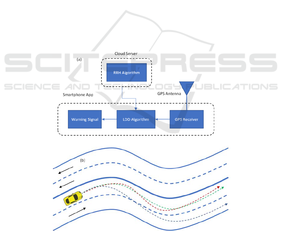
The architecture of the smartphone app combining the
previously developed RRH generation and lane
departure detection algorithms is shown in Figure 1a.
The GPS receiver acquires longitude and latitude
from the position of a moving vehicle in real-time to
be later used by both algorithms. RRH generation
algorithm extracts the RRH of a given road from a
vehicle’s past trajectories on that road. Please note
Figure 1: (a) The system architecture of the smartphone app using previously developed RRH and LDD algorithms. (b)
Conceptual diagram showing how past trajectories (red and green dashed line) of a given vehicle can be used to generate
RRH to detect a future lane departure (blue dashed line).
VEHITS 2023 - 9th International Conference on Vehicle Technology and Intelligent Transport Systems
224

that the RRH algorithm runs on a cloud server which
will be explained later. This algorithm uses an
adequate length of the GPS trajectory on a given road
to generate an RRH for that road. The RRH generated
is then used to detect any future unintentional lane
departure of the vehicle using the previously
developed LDD and RRH generation algorithms
(Figure 1a). The unintentional lane departure
detection using these two algorithms is illustrated in
Figure 1b, where the red and green dashed lines
represent a vehicle’s past trajectories, and the blue
dashed line represents unintentional lane departure.
Our proposed app will only be able to provide a
warning for those roads where the vehicle has
traveled in the past at least once because the necessary
RRH of travel for any given road requires at least one
past vehicle trajectory on that road. From the very
first trajectory, the necessary RRH is extracted and
saved for future use in the cloud database. During a
future trip on the same route, the app will retrieve the
RRH of that road and, using the LDD algorithm, will
detect a potential lane departure to warn the driver.
In addition to the two algorithms, the smartphone
app must establish a secure connection with the cloud
server to manage the extraction and retrieval of RRH
for multiple roads. We have selected Google Cloud
Platform (GCP) as our cloud server, which contains
two databases, one for trajectory upload and one for
RRH storage. Figure 2 describes the architecture of
GCP containing the two databases and its
interconnection with the smartphone app to manage
the secure connection and RRH extraction and
retrieval. While both databases will be described in
the following section, the secure connection and RRH
extraction and retrieval management are described
below.
2.1 Secure Connection
The first step for any smartphone running the app is
to securely connect to GCP to successfully share the
road trajectory and obtain the RRH of any road from
the cloud database. In order to do that, the smartphone
must exchange authentication credentials with the
GCP each time it connects to it.
While launching the app on a smartphone for the
first time, the app requires the user to create a
username, which can be anonymous for privacy
concerns. The authentication credentials are
associated with the username so that it can use those
credentials to establish a connection with GCP for
future use. The block showing “Firebase Auth” in
Figure 2 is responsible for the authentication process
between the smartphone app and GCP.
2.2 RRH Extraction and Retrieval
Management
For any given road, an RRH is generated using the
previously developed RRH generation algorithm as
soon as a new trajectory gets uploaded to the Firestore
database. The actual code for the RRH extraction
algorithm runs inside GCP using the Google cloud
function (Figure 2), a computation service provided
Figure 2: Schematic architecture of the smartphone app and its interconnection with GCP containing app database.
Development of a Smartphone App for Lane Departure Warning
225

by GCP. Google cloud function retrieves raw
trajectory data from the Firestore database and
converts it into a functional RRH. It also saves the
RRH in a structured database called “Postgres”
(lower right block in Figure 2). Whenever a
smartphone needs an RRH for any given road, it
requests the required RRH from the Google cloud
function by sending its current location. If the
relevant RRH exists in the Postgres database, the
cloud function retrieves it and forwards it to the
smartphone to detect lane departure using the
previously developed LDD algorithm. The
smartphone app database structure is discussed in
detail in the following section.
3 APP DATABASE STRUCTURE
The app database structure development is the most
crucial milestone toward the successful development
of the smartphone app. The app needs to retrieve the
corresponding RRH for any given road from the app
database using the vehicle’s current position to detect
and warn the driver of any unintentional lane
departure. This situation is analogous to the initial
locking mechanism of a GPS receiver in which a
vehicle (with a GPS receiver) is pinpointed at its
current location on the map from an extensive
mapping database. Similarly, for a vehicle traveling
on a particular road for the very first time, our
database structure has the ability to expand itself to
accommodate the new RRH as well as to keep the
provision for updating each existing RRH if and when
more future trajectories are available for any given
road which are already part of the database.
Furthermore, the algorithm to extract RRH from past
trajectories applies to large tracts of vehicle
trajectories. However, sometimes trajectories include
unnecessary portions of data like turns on highways
and entrances/exits on freeways which require
exclusion from the RRH before making it a part of the
database. This process demands developing a
structured app database to format and store RRH for
multiple roads in one place.
Although the app database can reside in the
memory of a smartphone, we opted for a cloud
service, i.e., GCP, to accommodate the app database
structure to allow multiple users to have access to the
RRH generated by any participating user. Please note
that the RRH generation algorithm will run on the
cloud server, and the LDD algorithm will run on the
smartphone. Therefore, multiple vehicles traveling on
the same or different roads can upload their
trajectories for the GCP to extract RRH for all those
roads. Resultingly, an RRH generated by one vehicle
can be potentially used by another vehicle for lane
departure detection.
The app database is structured into two separate
databases, one for trajectory upload and one for RRH
storage, both of which are described below.
3.1 Trajectory Upload
Once a smartphone establishes a secure connection
with GCP, it can upload its trajectory to GCP, which
will reside in a “NoSQL” database called “Firestore”
provided by the GCP.
A NoSQL database is appropriate for
accommodating a large amount of data without much
structure. Such a database is mainly used to house a
large amount of raw data, especially if the data are
temporary in nature. In our case, any road trajectory
from even a short trip can contain a large volume of
data which is only temporarily needed for RRH
extraction and can be discarded later after successful
extraction of each RRH. The nature of the data can be
a good estimation tool for the amount of data present
in a raw trajectory. Any trajectory data consists of a
collection of GPS data points where each point is
represented as a snippet of data, as shown in Figure 3.
This snippet of data is stored in Google Firestore
(NoSQL database). The GPS device can generate up
to 10 such points every second while the smartphone
travels along a road producing a large amount of data.
{
// Provided by GPS chip on phone.
“accuracy”: 3,
“heading”: 347,
“latitude”: 38.74422308172889,
“longitude”: -77.19622757445973,
// Provided by Google Roads API
“googleLatitude”:
38.74421031329726,
“googleLongitude”: -
77.19629289235164,
// Generated by our app.
“isManipulated”: true,
“timeStamp”: “2021-06-19
00:03:42.022Z”
}
Figure 3: Snippet of data stored in JSON format.
3.2 RRH Database
The RRH database is the most crucial element of the
app database structure because it accommodates the
RRH for all the roads. As stated before, the location
VEHITS 2023 - 9th International Conference on Vehicle Technology and Intelligent Transport Systems
226
of the RRH database is chosen in the GCP instead of
the smartphone’s memory to allow multiple app users
to upload their trajectories for RRH extraction so that
it is available for any app user. This feature will be
efficient when multiple users will use and test the app
during the beta testing phase. Additionally, this
provides a platform for commercial apps like Google
Maps to integrate the app feature within their
environment. The structure also allows the database
to expand itself to accommodate the new RRH (when
a vehicle with a smartphone travels on a given road
for the first time) as well as to keep the provision for
updating each existing RRH when more future
trajectories are available for any given road that are
already part of the database.
Due to its highly structured nature, a SQL
database called Postgres (bottom right block in Figure
2) is used, which is accessible within the GCP. This
database contains RRH for all road sections, along
with the road name and other relevant parameters.
The relevant parameters of each section of the road
are the start and end points (longitude and latitude),
path average heading (PAH) for the straight sections,
and initial heading (IH), and path average heading
slope (PAHS) for the curve or transition sections.
Whenever a vehicle needs to retrieve an RRH for a
given road, it sends a query to the Postgres database
to retrieve the required RRH using the road name and
the position of the two end points of various sections
of any road present in the database. The RRH of each
section of the road also contains a parameter called
“degree of confidence,” or DoC, which has an integer
value indicating the number of times a particular
RRH has been previously updated. For example, a
DoC value of “1” implies that only one trip generated
the RRH for that road. A DoC value of 2 or 3 means
that two or three past trajectories have been used for
that RRH. Multiple trajectories can be either from the
same vehicle traveling on that road at different times
or by different vehicles traveling on the same road
either at the same time or at different times.
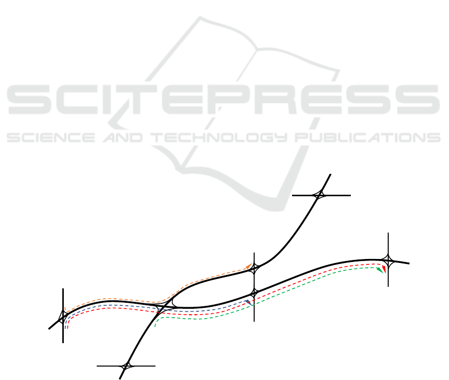
A typical road structure containing two freeways
(FW1 and FW2) is shown in Figure 4 to explain the
RRH database (SQL database). Four different
trajectories are also shown in the Figure using colored
dashed lines. After a trajectory is uploaded in the
NoSQL database (Firestore), it is processed by the
Google cloud function to generate RRH using the
RRH generation algorithm for that road segment.
After generating an RRH, the Google cloud function
stores all sections of RRH in the SQL database
(Postgress). The structure of this database is shown in
Table 1, with a grey highlighted area. The first three
columns of the table (not highlighted) are not part of
the database but have been included to explain the
process of updating the RRH resulting from various
trajectories.
After the first trajectory (dashed blue line in
Figure 4) is uploaded and converted to RRH, all the
relevant parameters of each section of the RRH are
stored in the database along with the road name and
DoC value. In this case, the road name is FW1, and
DoC is 1 for all sections. After the RRH resulting
from this trajectory is saved in the database, a total of
7 entries are made corresponding to 7 sections, as can
as can be seen in Table 1.
Figure 4: A typical road infrastructure containing two freeways to illustrate RRH database structure. The colored dashed lines
are trajectories on that road obtained at different times.
FWY1
FWY2
Exit1.1
Exit1.3
Exit1.4
Exit1.2/2.2
Exit2.1
Exit2.3
Exit2.4
Development of a Smartphone App for Lane Departure Warning
227
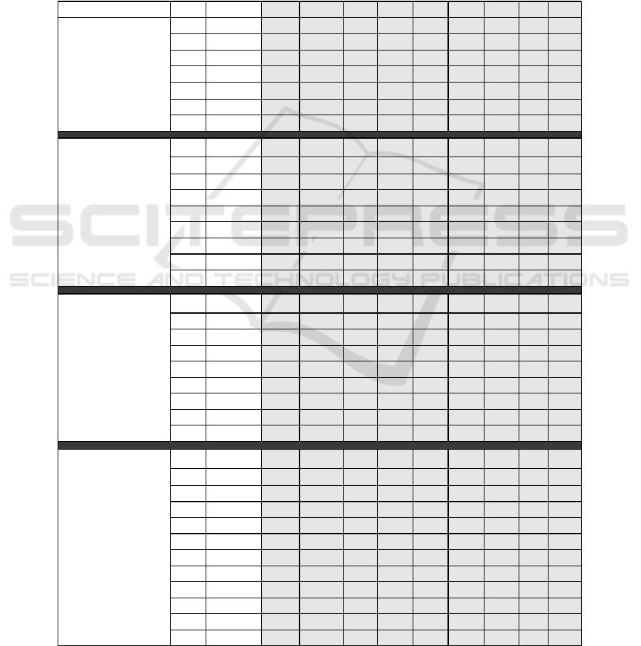
When the second trajectory (red dashed line in
Figure 4) is available and converted to an RRH, the
database entries are updated (Table 1). As seen in
Figure 4, the new trajectory (red dashed line) is
simply the extension of the first trajectory (blue
dashed line). Therefore, the new RRH contains some
of the old sections for the part of the road from the
first trajectory as well as some new sections for the
new part of the road. In this case, the first seven
sections (already present) are updated, and two more
new sections are added, as shown in Table 1
(Trajectory #2). If a section is updated, its DoC value
is increased by one and remains 1 for the new
sections. Please note that the last section or section #7
resulting from the first trajectory may get modified
when RRH sections are generated from the second
trajectory because the last section (either curve or
straight) may get extended and the endpoint may
differ from the previous point. For that purpose, this
section will be either updated or remain the same
depending upon how long the extension is. As a rule
of thumb, if it is not extended by more than 20% in
Table 1: RRH database showing updated database after every new trajetory.
ReferenceItenerary Count Comment Road DoC Start Start End End PAH IH PAHS
1new FW11 x x x x x x
2new FW11 x x x x x x
3new FW11 x x x x x
4new FW11 x x x x x x
5new FW11 x x x x x x
6new FW11 x x x x x x x
7new FW11 x x x x x
1 update FW1 2 x x x x x x
2 update FW1 2 x x x x x x
3 update FW1 2 x x x x x
4 update FW1 2 x x x x x x
5 update FW1 2 x x x x x x
6 update FW1 2 x x x x x x x
7 update* FW1 1or2 x x x x x
8new FW11 x x x x x x
9new FW11 x x x x x x
1FW12xxxxxx
2FW12xxxxxx
3 update* FW1 2or3 x x x x x
4 update FW1 3 x x x x x x
5 update FW1 3 x x x x x x
6 update FW1 3 x x x x x x x
7 update FW1 2 x x x x x
8 update FW1 2 x x x x x x
9 update FW1 2 x x x x x x
1 update FW1 3 x x x x x x
2 update FW1 3 x x x x x x
3 update* FW1 3or4 x x x x x
4FW13xxxxxx
5FW13xxxxxx
6 FW13 xxxxxxx
7 FW12 xxxxx
8FW12xxxxxx
9FW12xxxxxx
10new FW21 xxxxx
11new FW21 xxxxx
12 new FW1 1 x x x x x x
gp y j y
Trajectory#1
(bluedashedline)
fromExit1.1.to1.3
Trajectory#2
(reddashedline)
fromExit1.1toExit
1.4
Trajectory#3
(greendashedline)
fromExit1.2to1.4
Trajectory#4
(orangedashedline)
fromExit1.1to2.3
VEHITS 2023 - 9th International Conference on Vehicle Technology and Intelligent Transport Systems
228

length, we will not consider this as a different section
and increase the DoC value by one. However, if it gets
extended by more than 20%, we will call it a different
section and keep the Doc value to 1. In the future, we
will also consider setting some margins for other
parameters (PAH or IH and PAHS) of a given section
of the RRH to decide on updating the existing section.
4 APP USER INTERFACE AND
FUNCTIONALITY
After establishing the RRH database and the RRH
generation algorithm in GCP, the LDD algorithm is
programmed in the smartphone memory using the
smartphone processor and its GPS receiver. Our
developed smartphone app’s user interface and
functionality are described below. Please note that
currently, the app works for Android-based phones
only. In the future, we intend to develop a similar app
for iOS-based smartphones.
4.1 App User Interface
Once our app is installed on a smartphone and started,
a pop-up screen will appear asking for permission
whether the app can access the device’s location
using the device’s GPS receiver. Figure 5a shows a
screenshot where our app asks the user to choose if
the user wants to share a precise or approximate
location with the app. The user will have three options
to choose from: “While using the app,” “Only this
time,” or“Don’t allow.” The user’s preferences will
be saved once and will not be shown to the user again,
although a user can change these settings anytime
using the settings menu.
After saving the location preferences, signing in
will be required to establish a secure connection to
upload the trajectories and extract the RRH for a
given road from GCP. The sign-in page is shown in
Figure 5b, where users can register using a valid
email and a password of their choice. These
credentials will be required to log in to the app for
every use. The app must be active in the foreground
to take the GPS data and for the lane departure
detection algorithm to work. However, if the app runs
in the background, it will not collect any GPS points,
and neither the LDD algorithm will work. Once the
user logs in to the app, and it is running in the
foreground, the vehicle’s current position will appear
on the map of the smartphone app screen as a blue
dot, as shown in Figure 5c. Typically, a comfortable
view of about ± 100m around the vehicle’s position is
shown on the map of the app screen. Users can zoom
in or zoom out according to their comfort level.
4.2 Functionality
While traveling on the road with the app running in the
foreground, the LDD algorithm will be active and be
able to detect any lane departure and issue an audible
warning. In the future, when the app gets integrated
into a vehicle’s navigation system, the app will be able
to differentiate between intentional and unintentional
lane departures using the turn signal indicator. For
now, our app will issue an audible warning for all lane
departures, including intentional lane changes.
(5a) (5b) (5c)
Figure 5: (a) Screenshot of the app seeking user permission to access the device’s location. (b) Screenshot of the registration
page of the app. (c) Screenshot of the app showing the device location on the map.
Development of a Smartphone App for Lane Departure Warning
229
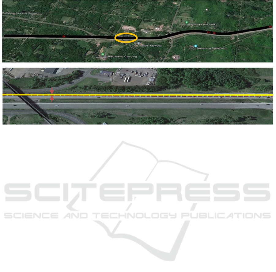
Figure 6: (6a) Picture from the Google Map of the 7 km route on Interstate I-35 with one lane departure highlighted with a
yellow circle. (6b) A zoomed in picture of the lane departure portion circled in yellow in (6a) indicating the lane width with
yellow lines. The lane change inside the yellow circle was made from left to right.
To demonstrate the app’s functionality in the
field, we drove the smartphone running our app in a
vehicle on a 7 km segment of Interstate I-35 near
Duluth, MN, for which an RRH was already
generated from a previous trip. The test vehicle was
driven within the speed limit (70 MPH) on the 4-lane
freeway (2 lanes each way), and many back-and-forth
lane changes were made intentionally in each test run.
For safety reasons, intentional lane changes were
made to test the accuracy of lane departure detection
using the LDD algorithm. The app successfully
identified the lane changes made during the test run
and issued an audible warning. The detection is
completed within a few GPS cycles, where each GPS
cycle is 100 msecs. Normally, the lane departure is
detected for a little less than a second. The accuracy
of our lane departure on any given road depends upon
the accuracy of the RRH of that road. On curved
portions, the accuracy may not be as much as on
straight portions. However, unintentional lane
departures occur mainly on long stretches of straight
road portions as opposed to curved road sections
where the driver must be attentive anyway. Figure 6a
depicts a picture from Google Maps, showing a
typical trajectory of the test run with a lane change
circled in yellow. The zoomed-in portion of this part
of the trajectory with a lane change (from left to right)
is shown in Figure 6b. Please note that the trajectory
with GPS points is shown as a continuum of small
circles laterally shifting from left to right for a lane
change. The lateral shift is approximately one lane
width, as illustrated in Figure 6b, with two yellow
lines. The app development is a work in progress.
Once the app is completely developed, we plan to do
more elaborate field testing and characterize the
accuracy of lane departure detection, which will be
reported in a future publication.
5 CONCLUSIONS
We have developed a smartphone app incorporating
two of our previously developed algorithms to detect
lane departure and warn the driver in real-time. Our
app is appropriate for use on longer stretches of
freeways or rural highways as opposed to urban areas
where the GPS signal is not as strong. Currently, the
app works for Android-based smartphones only, but
we plan to develop a similar app for iOS-based
smartphones as well. Our Android-based app is
almost ready for extensive field testing, and we are in
the middle of doing those tests. After thoroughly
testing our app, we will launch it for public use.
ACKNOWLEDGEMENTS
The authors wish to acknowledge those who made
this research possible. This work was made possible
by Minnesota cities and counties by the Local Road
Research Board with support from MnDOT’s Office
of Research & Innovation.
Lanewidth
VEHITS 2023 - 9th International Conference on Vehicle Technology and Intelligent Transport Systems
230

REFERENCES
An, X., Wu, M., & He, H. (2006). A novel approach to
provide lane departure warning using only one
forward-looking camera. International Symposium on
Collaborative Technologies and Systems (CTS’06),
356–362.
Chowdhury, S., Hossain, M. T., & Hayee, M. I. (2021).
Generation of Road Reference Heading using GPS
Trajectories for Accurate Lane Departure Detection.
VEHITS, 584-593.
Cicchino, J. B. (2018). Effects of lane departure warning
on police-reported crash rates. Journal of Safety
Research, 66, 61–70.
Clanton, J. M., Bevly, D. M., & Hodel, A. S. (2009). A low-
cost solution for an integrated multisensor lane
departure warning system. IEEE Transactions on
Intelligent Transportation Systems, 10(1), 47–59.
Dobler, G., Rothe, S., Betzitza, P., & Hartlieb, M. (2000).
Vehicle with optical scanning device for a lateral road
area. Google Patents.
Faizan, M., Hussain, S., & Hayee, M. I. (2019). Design and
development of in-vehicle lane departure warning
system using standard global positioning system
receiver. Transportation Research Record, 2673(8),
648–656.
Hsiao, P.-Y., & Yeh, C.-W. (2006). A portable real-time
lane departure warning system based on embedded
calculating technique. 2006 IEEE 63rd Vehicular
Technology Conference, 6, 2982–2986.
Hsiao, P.-Y., Yeh, C.-W., Huang, S.-S., & Fu, L.-C. (2008).
A portable vision-based real-time lane departure
warning system: Day and night. IEEE Transactions on
Vehicular Technology, 58(4), 2089–2094.
Jung, C. R., & Kelber, C. R. (2004). A lane departure
warning system based on a linear-parabolic lane
model. IEEE Intelligent Vehicles Symposium, 2004,
891–895.
Leng, Y.-C., & Chen, C.-L. (2010). Vision-based lane
departure detection system in urban traffic scenes.
2010 11th International Conference on Control
Automation Robotics & Vision, 1875–1880.
Lin, Q., Han, Y., & Hahn, H. (2010). Real-time lane
departure detection based on extended edge-linking
algorithm. 2010 Second International Conference on
Computer Research and Development, 725–730.
Lindner, P., Richter, E., Wanielik, G., Takagi, K., & Isogai,
A. (2009). Multi-channel lidar processing for lane
detection and estimation. 2009 12th International IEEE
Conference on Intelligent Transportation Systems, 1–6.
Maag, C., Muhlbacher, D., Mark, C., & Kruger, H.-P.
(2012). Studying effects of advanced driver assistance
systems (ADAS) on individual and group level using
multi-driver simulation. IEEE Intelligent
Transportation Systems Magazine, 4(3), 45–54.
McCall, J. C., & Trivedi, M. M. (2006). Video-based lane
estimation and tracking for driver assistance: Survey,
system, and evaluation. IEEE Transactions on
Intelligent Transportation Systems, 7
(1), 20–37.
Officials, T. (2008). Driving Down Lane-departure
Crashes: A National Priority. AASHTO.
Yu, B., Zhang, W., & Cai, Y. (2008). A lane departure
warning system based on machine vision. 2008 IEEE
Pacific-Asia Workshop on Computational Intelligence
and Industrial Application, 1, 197–201.
Development of a Smartphone App for Lane Departure Warning
231
