
Accuracy Assessment of Direct Georeferencing Using UAV Matrice
210 RTK V2 on Gully Santiš, Island of Pag (Croatia)
Katarina Glavačević
1
, Ivan Marić
2
and Ante Šiljeg
2
1
Independent Researcher, Ludwigshafen am Rhein, Germany
2
Department of Geography, University of Zadar, Zadar, Croatia
Keywords: Direct Georeferencing, Matrice 210 RTK V2, Absolute Accuracy, D-RTK 2, UAV Photogrammetry.
Abstract: Rapid development and increased availability of unmanned aerial vehicles (UAVs) resulted in the exponential
use of these systems in many scientific fields and activities. However, the application of photogrammetric
models derived using the Structure from Motion (SfM) technique largely depends on the use of ground control
points (GCPs). Since the acquisition of the GCPs requires the use of high-quality total stations or GNSS-RTK
receivers, these procedures generally take up a lot of time. Execution of a photogrammetric process without
using the GCPs is called direct georeferencing, and it is becoming an increasingly popular method. In this
research, we tested three methods of RTK positioning using the system of the Matrice 210 RTK V2 and D-
RTK 2 mobile station. The following methods were tested: (a) D-RTK 2 as a base station; (b) D-RTK 2
correction with the third-party base station; (c) network NTRIP corrections CROPOS. An absolute accuracy
assessment of each RTK positioning mode was done using 10 check points (CPs). By calculating the total
RMSE, it was determined that (b) and (c) RTK positioning modes have a centimeter level of accuracy (<10
cm). In this research, it is determined that the tested UAV system for direct georeferencing can be used in a
wide range of geographical applications and other disciplines where absolute accuracy of centimeter-level is
required.
1 INTRODUCTION
The knowledge of accurate information about the
Earth's surface has always played a key role in the
development of scientific disciplines and activities
(Guptill and Morrison, 1995, Šiljeg et al., 2018).
Obtaining reliable spatial data is primarily based on
the development of modern geospatial technologies
(GST) (Linder, 2009). Accurate, precise, and fast
collection of topographic data is becoming the basis
of physical geography (Smith et al., 2016), other
sciences, and sub-disciplines (Pike et al., 2009).
Aerial, UAV and terrestrial photogrammetry is
becoming a dominant technology in the study of
various spatio-temporal changes. In recent years,
obtaining high-resolution topographic models has
been based on the application of UAV
photogrammetry (Stott et al., 2020) and the SfM
technique, which significantly accelerated the
photogrammetric process (Masiero et al., 2017). The
fundamental task of all photogrammetric techniques
is to derive the geometric features of a certain object
or scene (Dittrich et al., 2017). However, the
dominance of UAV/SfM photogrammetry is limited
by the need to mark and collect ground control points
(GCPs) and check points (CPs) using quality and
expensive GNSS receivers (Carbonneau and Dietrich,
2016). The GCPs and CPs need to be marked and
measured according to the optimal distribution, which
can be an extremely long and expensive process
(Sanz-Ablanedo et al., 2018). It is generally
considered that increasing the number of GCPs
results in better model accuracy (Oniga et al., 2018).
In the context of spatio-temporal analysis, additional
problems arise due to the fact that GCPs can move or
disappear due to surface deformations or weather
conditions. Ultimately, a major limitation of this
classic aerial photogrammetry approach is that
sometimes it is not possible to achieve optimal GCPs
and CPs distribution due to security or practical
reasons (e.g. landslides, flood, frozen or swampy
areas, etc.) (Zhang et al., 2019), the unavailability of
the GNSS receiver, high energy relief, shortage of
time, etc. Although the „classical“ way of performing
aerial photogrammetry is recognized as the most
important data collection method in the creation of
topographic maps, it has obvious disadvantages in
long production time, inefficiency, and dependence
184
Glava
ˇ
cevi
´
c, K., Mari
´
c, I. and Šiljeg, A.
Accuracy Assessment of Direct Georeferencing Using UAV Matrice 210 RTK V2 on Gully Santiš, Island of Pag (Croatia).
DOI: 10.5220/0011933700003473
In Proceedings of the 9th International Conference on Geographical Information Systems Theory, Applications and Management (GISTAM 2023), pages 184-191
ISBN: 978-989-758-649-1; ISSN: 2184-500X
Copyright
c
2023 by SCITEPRESS – Science and Technology Publications, Lda. Under CC license (CC BY-NC-ND 4.0)

on GCPs, etc. (Yuan and Zhang, 2008). A new
acceleration of the photogrammetric process comes
with the appearance of the direct georeferencing (DG)
method (Bláha et al., 2011, Rehak et al., 2013). The
DG method does not require GCPs acquisition and
aerotriangulation (AT) in the process of model
derivation (Rizaldy and Firadus, 2012). DG
represents a photogrammetric process in which
modeling is based on the direct measurement of six
exterior orientation (EO) parameters, that is, the
position (XYZ) of the camera, which is measured by
the GNSS receiver, and the orientation/inclination of
the camera (pitch, roll, and yaw), which is measured
by the inertial measurement unit (IMU), in real-time
(Rizaldy and Firadus, 2012). However, the absence of
GCPs represents a significant challenge in assessing
the model’s quality. The development of more
affordable UAV platforms capable of producing
models using the DG approach has begun in recent
years. Therefore, the research about accuracy and
suitability of such an approach as a full-fledged
topographic imaging method is currently increasing
(Liu et al., 2022, Zeybek, 2021, Carbonneau and
Dietrich, 2016). Therefore, this research examines the
accuracy of the DG approach using the popular UAV
(Matrice 210 RTK V2 and D-RTK2) platform. The
camera Zenmuse X7 DL-S 16mm F2.8 was used. The
main goal of the research was to assess the accuracy
of the DG method using the different modes of RTK
positioning: (a) D-RTK 2 as a base station; (a
1
) D-
RTK 2 as a base station with the addition of a few
GCPs; (b) D-RTK 2 correction with the third-party
base station STONEX S10; (c) Network NTRIP
corrections CROPOS.
Also, the following scenarios were tested:
(d) a classical photogrammetric approach using
GCP and CP; (e) method using embedded navigation
sensors (GPS/GNSS and IMU-MEMS) in UAVs.
The purpose of the research was to provide
guidelines for the use of this setup at various scale
(resolution). In this case study, the testing was not
performed under the best possible conditions, because
such conditions, especially in the case where the
application of direct georeferencing is required, are
not always possible. Therefore, the goal was to
determine whether this sensor system corresponds to
the manufacturer's claims in conditions (light wind,
vertically dissected terrain) that are not ideal.
1.1 Gully Santiš (Pag Island)
The research area is gully Santiš (1163 m²), located
on the southeastern coast of the Island of Pag
(Croatia) (Figure 1). The island is dominated by
Cretaceous-Paleogene carbonate deposits of
limestone and dolomite, smaller parts of Paleogene
flysch, and younger Quaternary deposits (Magaš,
2011). The gully was formed on accumulated thick
brown soil, the deposits of which are prone to surface
loss of material. The dimensions of the gully Santiš
are 80 x 15 m, with an area of 1163 m
2,
and a drainage
basin with an area of 0.18 km
2
(Šiljeg et al. 2021).
Figure 1: Location of gully Santiš in Croatia, Pag.
2 MATERIALS AND METHODS
The research methodology is divided into three main
steps that include: (A) marking and measurement of
ground control and check points (GCPs and CPs)
within the research area; (B) derivation of digital
surface models (DSM) and digital orthophoto (DOP)
using: (b
1
) classical photogrammetric image
workflow process (with GCPs and CPs) and (b
2
)
through different ways of RTK positioning (1 - D-
RTK2 as base station; 2 - D-RTK2 correction with a
third party base station; 3- network NTRIP correction
with CROPOS); (C) accuracy assessment of the
derived models.
2.1 Connection of the UAV System
The D-RTK 2 mobile station was placed on an open,
elevated area and was stabilized by a tripod using the
built-in level. Open space means an environment
without obstacles within a >200 m from the source of
high-power radio emissions. After installation D-
RTK 2 was not moved. The mobile station was turned
on, and a constant green light on the power indicator
Accuracy Assessment of Direct Georeferencing Using UAV Matrice 210 RTK V2 on Gully Santiš, Island of Pag (Croatia)
185
indicated that D-RTK2 was connected to ≥10
satellites. Then the (4th) operating mode was
selected, which is intended for work with Matrice 210
RTK V2. Successful connection is done if the
orientation and positioning status of the is in FIX
mode. The UAV takeoff location had to be visible
from the base station location. The selected location
in the middle of the gully was visible from the D-
RTK2 mobile station. UAV mission planning was
done in the DJI Pilot application, single-grid missions
were planned with a front and side photo overlap of
80%. The flight height was set at 30 m. The flight
speed in the mission was 2 m/s.
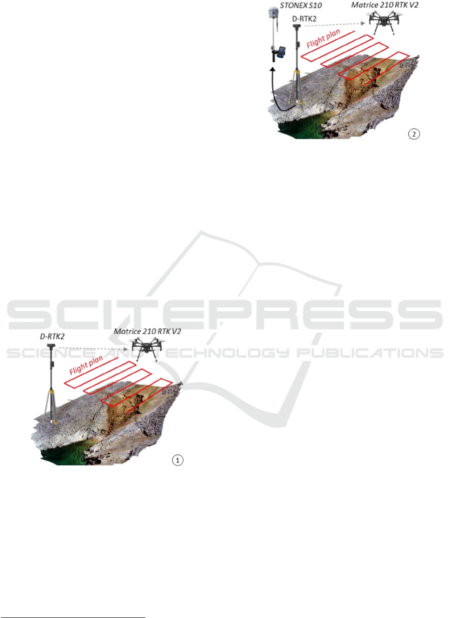
2.1.1 D-RTK 2 as Base Station
The first tested method of RTK positioning was the
D-RTK2 as base station. This method uses only the
D-RTK2 base station to transmit RTK information
directly to the UAV (Fig. 2). The base station is
turned on and it connects to the controller and the
UAV. The primary benefit of this method is very easy
set up. This workflow does not require an internet
connection. If the default coordinates measured with
D-RTR2 are used in the Z value, the height of the base
station does not have to be added. The D-RTK2
measures long. and lat. in decimal degrees (DD), and
altitude as height above ellipsoidal height (HAE
1
).
Figure 2: D-RTK2 as a base station.
2.1.2 D-RTK 2 Coordinate Correction with
a Stonex S10
In the second method of RTK positioning, the precise
determination of the D-RTK2 coordinates was
performed by using the STONEX S10 GNSS
receiver, which was mounted using a suitable tripod
on the same location as D-RTK2 (Fig. 3).
1
Height Above Ellipsoid
Figure 3: D-RTK2 coordinate correction with a STONEX
S10.
After the initialization of the receiver, the
measurement of the point where the D-RTK2 was
mounted lasted 2 min (10 measurement epochs). The
measured coordinates, using STONEX S10 and
NRTK modality, were entered in the DJI GO
application. The precision of the measurement was in
accordance with the official specifications of the
STONEX S10. Since there is no place in the
application to enter the height of the base station, the
measured coordinates representing the antenna phase
center (APC) of the D-RTK2 were entered (1.802 m)
(Buonanno, 2019). The height of the antenna is
calculated as follows: the tripod provided by DJI has
a height of 1,660 m from the end to the bottom of the
antenna. Adding the distance between the base of the
antenna and the phase center of the antenna (0.1419
m) gives a value of 1.802 m, which is added to the
reference height in the DJI GS RTK settings. In
summary, the measured coordinates representing the
phase center of the antenna (APC) D-RTK 2 are
entered. Table 1 shows the differences in the
coordinates of the location where the D-RTK 2
mobile station was mounted, measured by the
STONEX S10 and the D-RTK2 mobile station. The
D-RTK2 measured the height of the antenna almost
40 cm lower. The differences for longitude are about
73.3 cm and for latitude 43.9 cm. Therefore, the
assumption was that the model generated by RTK
positioning using the first operating mode, i.e. where
only D-RTK2 is used as a base station, will deviate
from the model derived by the classic approach in
similar values (long. ≈ 73.3 cm, lat. ≈ -43.869 cm,
elev. ≈ 38,60 cm).
GISTAM 2023 - 9th International Conference on Geographical Information Systems Theory, Applications and Management
186

Table 1: Differences in base station coordinates measured
with D-RTK2 (mode 1) and Stonex S10 (mode 2).
WGS84 X (dd) Y (dd) Z (m)
D-RTK2 15.19281974 44.37452990 69.331
Stonex S10 15.19281054 44.37453387 69.717
Diff. (cm) 73.366 -43.869 -38.60
2.1.3 Network NTRIP Correction with
CROPOS
In the third method of RTK positioning, the
Networked Transport of RTCM via the Internet
Protocol (NTRIP) connection option was used (Fig.
4). This methodology uses NTRIP without a base
station of any kind and provides live RTK data using
an NTRIP stream connected to the Internet. This
process requires an internet connection at the
recording location via local Wi-Fi, hotspot, or
dedicated 5G connection to the controller. The
advantage of this method is that using a networked
workflow requires the least amount of physical
equipment at the recording location. The biggest
disadvantage is the need for an active, reliable
internet connection. Even a brief interruption of the
Internet connection can cause problems.
Figure 4: Network NTRIP correction with CROPOS.
2.2 Marking and Acquisition of GCPs
and CPs
The arrangement of GCPs/CP was determined by the
type of shallow brown soil, extremely dynamic and
subject to erosion that prevails in the research area.
Furthermore, certain parts of the gully are extremely
vertically dissected with a large slope, which
complicates the process of marking and acquisition of
GCPs and CPs. The majority of points were marked
on limited rocky surfaces, which are characterized by
small surface slopes. A total of 10 points were marked
and collected in the research area in order to verify
the accuracy of the derived models. The coordinates
were collected using a STONEX S10 GNSS receiver
which in RTK mode has a horizontal accuracy of 0.8
cm and a vertical accuracy of 1.5 cm. After the
initialization, the points were measured in one
independent measurement, and each point was
measured for 2 min (10 measurement epochs) (Fig.
5). The coordinates of the marked points were
collected in the WGS84 coordinate system in decimal
degrees (DD), while the altitude was collected as
ellipsoidal height (HAE).
Figure 5: Acquisition of GCPs and CPs.
2.3 Processing of UAV Images
In each mission about 240 images were collected.
Flight time of each mission was 14 minutes. UAV
images were processed using Agisoft Metashape
1.5.1. software. The process consisted of seven
commonly known steps in the SfM photogrammetry
process (Marić et al., 2019): (1) image quality
checking; (2) camera accuracy settings; (3) align
photos; (4) gradual selection and optimization of the
camera position; (5) adding GCPs and/or; (6) build a
dense cloud, mesh, and texture; (7) build and export
digital surface model (DSM), and digital orthophoto
(DOP). The quality of all photos was assessed. Those
photos with a quality value < 0.5 were deleted. In the
first step (align photos) about 20 million tie points
were generated. The accuracy parameter in align
photos is set to high, and the key point limit and ie
point limit are set to 40000 and 8000. Interior camera
calibration parameters were determined
automatically after alignment. Using the gradual
selection, all tie points with reprojection error greater
than 0.2 and reconstruction uncertainty greater than
20 were deleted. The GCPs and CPs were added to
the reconstructed sparse point cloud. In some models,
all points served as GCPs, while in others, all points
served as CPs. In cases where GCPs/ CPs were added,
and the reconstructed model was updated, it was
observed that certain camera locations (photos) have
a significant positioning error (e.g. >40 cm).
Therefore, a smaller number of these photos were
Accuracy Assessment of Direct Georeferencing Using UAV Matrice 210 RTK V2 on Gully Santiš, Island of Pag (Croatia)
187
deleted, which were mostly located at the edges of the
mission. This process decreased the model error.
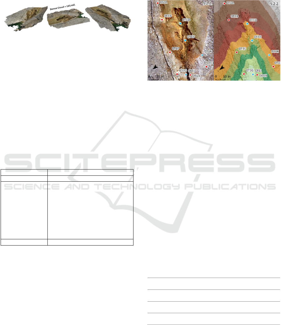
DSM and DOP were derived from the point cloud,
which had approximately 101 million points (Fig. 6).
Figure 6: Derived dense point cloud.
3 RESULTS
3.1 GCP and Check Points
All points were collected using GNSS Stonex S10
and NRTK modality, and the precision of the
measurement was calculated from 10 measurements
collected at each point. Table 2 shows the mean range
value for XYZ coordinates. The precision of the
collected points corresponds to the specified factory
precision of the receiver. The X coordinate deviates
on average by 0.83 cm, the Y coordinate the same,
and the Z coordinate slightly higher (Table 2).
Table 2: The average range of XYZ coordinate values.
Range (cm)
GCP/CP X Y Z
A 0.61 0.69 0.90
B 0.73 0.77 1.80
D 0.37 0.80 0.7
E 0.90 1.06 1.00
F 1.18 0.80 0.90
G 0.71 0.88 1.2
H 1.13 0.74 1.30
I 1.01 0.91 0.50
J 0.97 0.91 1.00
K
0.72 0.70 0.70
MEAN 0.83 0.83 1.00
3.2 The Classical Photogrammetric
Methods
The classic method refers to the dominant way of
performing the UAV photogrammetry process (Fig.
7). In this image processing workflow, the D-RTK 2
mobile station was not used. The collected GCPs
(n=6) were used to position the reconstructed model
in a global coordinate system, while the CPs (n=4)
were used to check the accuracy of the model.
The recorded surface area was 0.0143 km². The
ground samplig distance (GSD) of the DOP was 6.62
mm, and the DSM was 1.32 cm. Point density was
5700 points/m². From the added CPs the root mean
square error (RMSE) was calculated. The RMSE for
the X coordinate
was 1.33 cm, for the Y 1.28 cm, and
for the Z 2.76 cm. The total RMSE of this model was
3.32 cm.
Figure 7: Derived DOP and DSM (classical method).
3.3 Direct Georeferencing
3.3.1 D-RTK 2 as Base Station
In this method of RTK positioning the D-RTK 2
mobile station was used. All collected points were
used as CP (n=10) (Fig. 8). The RMSE for the X
coordinate was 75.89 cm, for the Y 34.98 cm, and for
the Z 26.94 cm. The total RMSE was 87.80 cm. The
large total RMSE is not surprising the difference in
the coordinates of the mobile station location
measured by D-RTK 2 itself and those by Stonex S10
is known (Table 1). The total RMSE was extremely
large (87.809 cm) due to the incorrect measurement
of the location of D-RTK 2. In this reconstructed
model, a smaller number of GCPs were added, with
the aim of determining their impact on model
accuracy. An iterative assessment of the accuracy of
the model was performed (Table 3), first with one,
then two, and finally with three GCP added. Thus, in
the 1
st
scenario, nine CPs were used, in the 2
nd
eight,
and in the 3
rd
seven CPs.
Table 3: The accuracy of different scenarios (D-RTK +
GCPs).
X error
(cm)
Y error
(cm)
Z error
(cm)
Total
(cm)
D-RTK2
+1GCP
20.37 11.68 31.99 39.68
D-RTK2
+2GCP
21.57 9.36 23.05 32.93
D-RTK2
+3GCP
15.10 7.36 9.08 19.09
It can be seen that the total RMSE decreases with
the addition of GCPs. By adding just one GCP, the
total RMSE decreased by 48.129 cm. The second
GCP reduced the RMSE by 6.75 cm, and the third by
GISTAM 2023 - 9th International Conference on Geographical Information Systems Theory, Applications and Management
188

13.84 cm. The total RMSE was reduced by 68.719 cm
by adding only three GCPs.
Figure 8: Derived DOPs and DSMs. (A) D-RTK; (B) D-
RTK+1GCP; (C) D-RTK+2GCP; (D) D-RTK+3GCP.
3.3.2 D-RTK 2 Coordinate Correction with
STONEX S10
In this method of RTK positioning a GNSS receiver,
Stonex S10 was used in measuring the exact
coordinates of the location of the D-RTK 2 mobile
station. As in the first scenario on all acquired points
were used as CPs (n=10). The RMSE for the X
coordinate was 4.09 cm, for the Y 2.69 cm, and for
the Z 5.97 cm. The total RMSE of this model was 7.72
cm. The points “OT1A” and “OT1B”, which were
located on the least number of photos, had the highest
total RMSE. If these two points were excluded from
the analysis, the total RMSE of the model derived by
RTK positioning using the Stonex S10 correction
would amount to 5.99 cm.
3.3.3 Network NTRIP Corrections with
CROPOS
In this method of RTK positioning the NTRIP
connection option with CROPOS (Croatian
Positioning System) was used, providing real-time
RTK data without a base station on the site. All
collected points were used as CPs (n=10) (Fig. 9). The
RMSE for the X coordinate was 4.044 cm, for the Y
2.228 cm, and for the Z 4.488 cm. The total RMSE of
this model is 6.44 cm. The points “OT1A” and
“OT1B”, which were located on the least number of
photos (15 and 25), had the highest total RMSE. If
these two points were excluded from the analysis, the
total RMSE of the model derived from RTK
positioning using the network NTRIP correction
would be 5.31 cm.
Figure 9: Derived DOP and DSM (NTRIP connection with
CROPOS).
3.4 Absolute Accuracy of Tested RTK
Positioning Modes
The official specifications that can be found for many
sensor systems are usually tested and determined
under best-case scenarios. In this case, the testing was
not performed under best-case scenarios precisely
because such conditions, especially in the case where
the application of direct georeferencing is required,
are not always possible. In general, the goal was to
determine if this sensor system corresponds to the
manufacturer's own claims in conditions that are not
ideal. It was found that the accuracy of direct
georeferencing using the Matrice 210 RTK V2 and
the D-RTK 2 depends on the selected mode of
operation. Three modes of RTK positioning were
tested. Table 4 shows the summary results of XYZ
and total RMSE for the derived models. The highest
accuracy, as expected, was achieved in scenario (d)
with the application of GCP and CP resulting in a
total RMSE of 3.22 cm. Furthermore, the centimeter
level of accuracy (<10 cm) was achieved in the
operating mode where the (c) NTRIP connection
option with CROPOS was used, which enables the
positioning of the UAV in real-time, and in the
operating mode where the (b) corrective coordinates
collected by the Stonex S10 receiver were used
(Table 4). These two methods give similar results,
which is expected considering that the STONEX S10
uses the CROPOS system of base stations. The
Accuracy Assessment of Direct Georeferencing Using UAV Matrice 210 RTK V2 on Gully Santiš, Island of Pag (Croatia)
189

advantage of the first method is, that using a network
NTRIP connection option, requires the least amount
of equipment at the recording location. The biggest
disadvantage is the need for an active, reliable
Internet connection. In the second method, another
high-precision GNSS receiver is needed, which could
measure the coordinate on which the D-RTK 2
mobile station was mounted.
Table 4: Summary data on the accuracy of all tested RTK
positioning methods.
Scenario
X error
(cm)
Y error
(cm)
Z error
(cm)
Total
(cm)
D 1.33 1.28 2.76 3.32
C 4.04 2.23 4.49 6.44
B 4.06 2.69 5.97 7.72
A1 +3GCP 15.10 7.36 9.08 19.09
A1 +2 GCP 21.57 9.36 23.05 32.93
A1 +1 GCP 20.37 11.68 31.99 39.68
A 75.90 34.98 26.94 87.81
E 75.48 70.78 93.78 139.7
(a) D-RTK 2 as a base station; (a
1
) D-RTK 2 with the addition of
few GCPs; (b) D-RTK 2 correction with the Stonex S10; (c)
network NTRIP corrections CROPOS; (d) classical approach using
GCP and CP; (e) method using embedded navigation sensors into
UAVs.
The large total RMSE of 87.81 cm which is recorded
for D-RTK 2 is not surprising considering the
differences in the location coordinates of the mobile
station measured by D-RTK 2 itself and those by
STONEX S10 (Table 1). Therefore, the deviation in
the location of D-RTK 2 contributed to this error
(Table 4). Namely, in the official specifications, it is
stated that the accuracy of RTK positioning is
centimeters (horizontal = 1 cm, vertical = 2 cm). This
means that, in ideal recording conditions (absence of
wind), the relative accuracy of the positioning of the
cameras (photos location) will be in centimeters.
However, the single point (absolute) accuracy is 1.5
m horizontally and 3 m vertically. Therefore, this
result is not surprising. By including a smaller
number of GCPs (n=3) there is a significant reduction
in model error (87.81 cm - 19.09 cm). However, the
final total RMSE is still too large (19.09 cm) to justify
the use of XYZ coordinates of the photos in model
orientation. Based on this research, it can be
concluded that, if the D-RTK 2 mobile station retains
this level of absolute accuracy in reading its own
location (≈ 1 m), it is not worth using a smaller
number of GCPs in the orientation of the model,
because ultimately, in order to obtain satisfactory
accuracy, a larger number of them should be added (>
3), which would make the very application of D-RTK
2 senseless if it is about the smaller surface. In
scenario (E), the D-RTK 2 mobile station was not
used for positioning, and GCPs were not used in the
photogrammetric process. The RTK positioning
mode was turned off, and only the XYZ coordinates
of the photos from the UAV's GNSS receiver were
used. In this case, all 10 points were used to check the
accuracy of the model (CP=10). The RMSE for the X
coordinate was 75.5 cm, for the Y 70.8 cm, and for
the Z 93.8 cm. The total RMSE of this model was
139.7 cm. Nevertheless, the accuracy of positioning
is satisfactory considering that only XYZ data of the
photos, collected with the UAV's GNSS receiver,
were used in the process of model orientation.
4 CONCLUSIONS
The research tested three modes of RTK positioning
using the Matrice 210 RTK V2 system and D-RTK 2
mobile station. An assessment of the absolute
accuracy of the photogrammetric models was carried
out through the marking and collection of GCPs/ CPs
(n=10).
By calculating the total RMSE, it was determined
that two (NTRIP network correction with CROPOS
and STONEX S10 correction) of the three tested RTK
positioning modes have a centimeter level of
accuracy. It was found that the accuracy of RTK
positioning using the Matrice 210 RTK V2 and the D-
RTK 2 mobile station depends on the selected mode
of operation. These two methods give similar results,
which is expected given that the STONEX S10 uses
the CROPOS system of base stations. The third
method of RTK positioning, where the D-RTK
determines its location by itself, generates a large
absolute error. This error is not surprising,
considering the differences in the location
coordinates of the mobile station read by D-RTK 2
itself and those read by STONEX S10. This research
established that the tested UAV system for direct
georeferencing can be used in a wide range of
geographic sciences and other disciplines where
absolute centimeter accuracy of different models is
required.
ACKNOWLEDGEMENTS
This work has been supported in part by Croatian
Science Foundation under the project UIP-2017-
05-2694 and conducted within Center for
Geospatial Technology.
GISTAM 2023 - 9th International Conference on Geographical Information Systems Theory, Applications and Management
190

REFERENCES
Bláha, M., Eisenbeiss, H., Grimm, D., & Limpach, P.
(2011). Direct georeferencing of UAVs, In Proceedings
of the International Conference on Unmanned Aerial
Vehicle in Geomatics (UAV-g) (Vol. 38, pp. 131-136).
Copernicus.
Buonanno, M. (2019): D-RTK2 - User Notes - rev_200417,
CNR-ISAFOM, Italy.
Carbonneau, P. E., Dietrich, J. T. (2016): Cost‐effective
non‐metric photogrammetry from consumer‐grade
sUAS: implications for direct georeferencing of
structure from motion photogrammetry, Earth Surface
Processes and Landforms, 42(3), 473-486.
Dittrich, A., Weinmann, M., Hinz, S. (2017): Analytical
and numerical investigations on the accuracy and
robustness of geometric features extracted from 3D
point cloud data. ISPRS journal of photogrammetry
and remote sensing, 126, 195-208.
Guptill, S. C., Morrison, J. L. (1995). Looking ahead. In
Elements of spatial data quality (pp. 189-197).
Pergamon
Linder, W. (2009). Digital photogrammetry (Vol. 1).
Berlin: Springer.
Liu, X., Lian, X., Yang, W., Wang, F., Han, Y., Zhang, Y.
(2022): Accuracy assessment of a UAV direct
georeferencing method and impact of the configuration
of ground control points. Drones, 6(2), 30.
Magaš, D. (2011). Zemljopisna obilježja otoka Paga u
funkciji upoznavanja njegove toponimije. Toponimija
otoka Paga, 5-49.
Marić, I., Šiljeg, A., Domazetović, F. (2019): Geoprostorne
tehnologije u 3D dokumentaciji i promociji kulturne
baštine–primjer utvrde Fortica na otoku Pagu.
Geodetski glasnik, 50, 19-44.
Masiero, A., Fissore, F., Vettore, A. (2017). A low-cost
UWB based solution for direct georeferencing UAV
photogrammetry, Remote Sensing, 9(5), 414.
Oniga, V. E., Breaban, A. I., Statescu, F. (2018).
Determining the optimum number of ground control
points for obtaining high precision results based on
UAS images. In Multidisciplinary Digital Publishing
Institute Proceedings (Vol. 2, No. 7, p. 352).
Pike, R. J., Evans, I. S., Hengl, T. (2009).
Geomorphometry: a brief guide. Developments in Soil
Science, 33, 3-30.
Rehak, M., Mabillard, R., Skaloud, J. (2013): A micro-UAV
with the capability of direct georeferencing,
International Archives of the Photogrammetry, Remote
Sensing and Spatial Information Sciences, Volume XL-
1/W2, 4 – 6 September 2013, Rostock, Germany.
Rizaldy, A., Firdaus, W. (2012). Direct georeferencing: A
new standard in photogrammetry for high accuracy
mapping, International Archives of the
Photogrammetry, Remote Sensing and Spatial
Information Sciences, Volume XXXIX-B1, XXII
ISPRS Congress, 25 August – 01 September 2012,
Melbourne, Australia
Sanz-Ablanedo, E., Chandler, J. H., Rodríguez-Pérez, J. R.,
Ordóñez, C. (2018): Accuracy of unmanned aerial
vehicle (UAV) and SfM photogrammetry survey as a
function of the number and location of ground control
points used, Remote Sensing, 10(10), 1606.
Šiljeg, A., Barada, M., Marić, I. (2018): Digitalno
modeliranje reljefa, Alfa d.d., Sveučilište u Zadru,
Zadar.
Šiljeg, A., Domazetović, F., Marić, I., Lončar, N., Panđa, L.
(2021). New Method for Automated Quantification of
Vertical Spatio-Temporal Changes within Gully Cross-
Sections Based on Very-High-Resolution Models.
Remote Sensing, 13(2), 321.
Smith, M. W., J. L. Carrivick, D. J. Quincey (2016):
"Structure from motion photogrammetry in physical
geography." Progress in Physical Geography 40.2 247-
275.
Stott, E., Williams, R. D., Hoey, T. B. (2020): Ground
control point distribution for accurate kilometre-scale
topographic mapping using an RTK-GNSS unmanned
aerial vehicle and SfM photogrammetry. Drones, 4(3),
55.
Yuan, X., Zhang, X. P. (2008): Theoretical accuracy of
direct georeferencing with position and orientation
system in aerial photogrammetry. The International
Archives of the Photogrammetry, Remote Sensing and
Spatial Sciences, 617-622.
Zeybek, M. (2021). Accuracy assessment of direct
georeferencing UAV images with onboard global
navigation satellite system and comparison of
CORS/RTK surveying methods. Measurement Science
and Technology, 32(6), 065402.
Zhang, H., Aldana-Jague, E., Clapuyt, F., Wilken, F.,
Vanacker, V., Van Oost, K. (2019): Evaluating the
Potential of PPK Direct Georeferencing for UAV-SfM
Photogrammetry and Precise Topographic Mapping.
Earth Surf. Dyn. Discuss, 1-34.
Accuracy Assessment of Direct Georeferencing Using UAV Matrice 210 RTK V2 on Gully Santiš, Island of Pag (Croatia)
191
