
Towards Autonomous Mobile Inspection Robots Using Edge AI
Ricardo C. C
ˆ
amara de M. Santos
a
, Mateus Coelho Silva
b
, Rodrigo Lucas Santos
c
,
Emerson Klippel
d
and Ricardo A. R. Oliveira
e
Departmento de Computac¸
˜
ao - DECOM, Universidade Federal de Ouro Preto - UFOP, Ouro Preto, Brazil
Keywords:
Autonomous Mobile Robot, Inspection Robot, Robot, Edge AI, Artificial Intelligence, Deep Learning, CNN,
YOLOv7, Feedback Control, Object Detection, Jetson Xavier NX.
Abstract:
Recent technological advances have made possible what we call industry 4.0 in which the industrial environ-
ment is increasingly filled with advanced technologies such as artificial intelligence and robotics. Defective
products increase the cost of production and in such a dynamic environment manual methods of equipment
inspection have low efficiency. In this work we present a robot that can be applied in this scenario performing
tasks that require automatic displacement to specific points of the industrial plant. In this robot we use the
concept of Edge AI using artificial intelligence in a edge computing device. To perform its locomotion the
robot uses computer vision with the brand new YOLOv7 CNN and feedback control. As hardware this robot
uses a Jetson Xavier NX, Raspberry Pi 4, a camera and a LIDAR. We also performed a complete performance
analysis of the object detection method measuring FPS, consumption of CPU, GPU and RAM.
1 INTRODUCTION
The technological advances of the 21st century made
possible the fourth industrial revolution, also known
as industry 4.0. Industry 4.0 is the combination
of several technologies, such as digital technologies
(e.g., artificial intelligence, Internet of Things, and
blockchain) and other technological advances (e.g.,
robotics, digital twins, and cyber-physical systems)
all applied to an industrial production environment
(Hassoun et al., 2022). In this way, the industrial
environment is moving towards having a high-level
collaboration between robots and human workers to
increase safety, flexibility, and productivity.
Defective products increase costs and deteriorate
manufacturing processes. Inspection routines for the
preventive detection of anomalies and problems are
of paramount importance for efficiently maintaining
an industrial plant. Conventional manual inspection
methods have a high workload, offer risks and have
low efficiency. In addition, they cannot continuously
satisfy the increasing quality standards of the means
of production. Therefore, robots helps to reduce these
a
https://orcid.org/0000-0002-2058-6163
b
https://orcid.org/0000-0003-3717-1906
c
https://orcid.org/0000-0003-3795-9218
d
https://orcid.org/0000-0003-0312-3615
e
https://orcid.org/0000-0001-5167-1523
problems and it is one of the research focuses around
the world (Ebayyeh and Mousavi, 2020).
A fundamental component of Industry 4.0 is the
flexible manufacturing system, an advanced pro-
duction system that interconnects machines, work-
stations, and logistical equipment, with the entire
manufacturing process. This fabrication system is
intended for highly complex manufacturing tasks
of great topological diversity, guaranteeing delivery
times and minimum manufacturing costs and with
frequent changes (Florescu and Barabas, 2020). In
this way, the need for autonomy in the movement of
the automatic inspection agent arises. So the inspec-
tion agents should move to the inspection sites au-
tonomously and appropriately.
For this matter, we present an autonomous loco-
motion method based on Edge AI technology. This
work aims to present a robot capable of moving to
specific points of the production plant. These sensors
are a camera and a LIDAR. The robot moves to tar-
get positions using object detection in images through
the usage of a CNN (Albawi et al., 2017a) applied to
images captured from a camera installed on the robot.
LIDAR is used to measure the robot’s distance to the
target position and its arrival at the required positions.
Santos, R., Silva, M., Santos, R., Klippel, E. and Oliveira, R.
Towards Autonomous Mobile Inspection Robots Using Edge AI.
DOI: 10.5220/0011972200003467
In Proceedings of the 25th International Conference on Enterprise Information Systems (ICEIS 2023) - Volume 1, pages 555-562
ISBN: 978-989-758-648-4; ISSN: 2184-4992
Copyright
c
2023 by SCITEPRESS – Science and Technology Publications, Lda. Under CC license (CC BY-NC-ND 4.0)
555

2 THEORETICAL REFERENCES
This section presents the necessary theoretical frame-
work for creating the robot and its autonomous loco-
motion methodology.
2.1 Autonomous Mobile Robots
An autonomous mobile robot (AMR) is a system
designed for operation and navigation in an unpre-
dictable and partially unknown environment. For
this, the robot must navigate without interruption and
avoid collision with obstacles within a known con-
fined environment (Ishikawa, 1991). The AMR re-
quires little or no human intervention to navigate and
move around and is designed to follow a pre-defined
path, whether indoors or outdoors.
The fundamentals of mobile robotics consist of
locomotion, perception, and navigation (Alatise and
Hancke, 2020). Indoors, the mobile robot usually re-
lies on the floor plan, sonar location, and inertial mea-
surement unit (IMU), among other sensors. For the
robot to function, it needs to have a range of sensors
that offer an internal representation of the environ-
ment.
2.2 Convolutional Neural Networks
Machine Learning is a field of research in the sub-
field of Artificial Intelligence (AI) that studies the de-
velopment of methods capable of extracting concepts
from data samples. One of the methods used for this
purpose is artificial neural networks (ANN) that can
be understood as a non-linear mathematical model to
predict or generate content based on input data. Net-
works are formed by layers of neurons, which are
the basic units of networks. Each layer of neurons
is connected to each other through connections called
synapses which are the output signal of each neuron
and, at the same time, the input signal of the next
layer, so the information propagates through the net-
work. These synapses are associated with weights de-
fined during the training of the network so that the
model learns to process the information appropriately
(Krogh, 2008).
The term Deep Learning refers to ANN with
a considerable amount of layers. Interest in hav-
ing deeper hidden layers has outperformed classical
methods in different application areas, especially in
(Albawi et al., 2017b) pattern recognition. One of
the most popular deep neural networks is the Con-
volutional Neural Network (CNN). They take this
name because it is the name of the linear mathemat-
ical operation between matrices called convolution.
CNNs perform very well on machine learning prob-
lems. They have several layers that identify hierarchi-
cal patterns. These layers include convolutional layer
learning filters that run on the input image, forming
a feature map as output. Pooling layers are used to
subtract information from the previous layer. Upsam-
pling layers can be used to augment information. Ap-
plications dealing with image data are widely used for
object detection (Arulprakash and Aruldoss, 2022).
2.3 Edge AI
Current artificial intelligence applications, such as
deep learning, are techniques that require high com-
putational power for their execution, which creates
a technical challenge to adapt artificial intelligence
applications for embedded devices (Li et al., 2019).
Edge AI is a new perspective that benefits from Edge
Computing concepts to develop artificial intelligence
applications.
Edge computing and artificial intelligence, by na-
ture, have conflicting requirements. AI generally re-
quires more processing, while edge computing builds
primarily on hardware miniaturization and increased
mobility. However, a recent trend has shown an
increasing number of applications applying the two
concepts together, especially in mobile edge comput-
ing (Chen and Ran, 2019). In this way, the Edge
AI (Wang et al., 2019) concept has the challenge of
adapting AI and hardware models to make it possible
to develop applications for this context.
3 RELATED WORKS
In Szrek et al. (Szrek et al., 2022), a mobile inspec-
tion platform based on autonomous UGV (Unmanned
Land Vehicles) was proposed, equipped with various
sensors (RGB image, sound, gas sensor, among oth-
ers). They used a laboratory with a co-supplier test
cart designed for research purposes. The process was
divided into two parts: inspection planning and exe-
cution. The units are controlled by a module based
on an STM32 microcontroller with an ARM Cortex
M3 core. They employ a SLAM algorithm for lo-
calization and mapping while using MQTT to com-
municate within the modules. Once again, this robot
relies on heavy modules, sensor fusion, and predeter-
mined algorithms to perform its task. It also differs
from our approach as it does not use AI and relies on
more algorithms, more sensors, and heavier modules
to perform the task
Dandurand et al. (Dandurand et al., 2022) present
a system used in Hydro-Quebec of an all-weather au-
ICEIS 2023 - 25th International Conference on Enterprise Information Systems
556

tonomous inspection robot for electrical substations
capable of acting in all climatic situations. In particu-
lar, it aims at substations subject to severe winter con-
ditions in northern countries. The solution uses real-
time kinematic positioning (RTK) for location and an
IMU for attitude awareness. This system also em-
ploys a set of fixed algorithms and does not rely on AI
to perform any task. Although it is also meant for in-
spection, the applications differ from those proposed
in this work in a similar way as the previous ones.
Salimpour (Salimpour et al., 2022) et al. propose
a comprehensive deep-learning framework capable of
monitoring anomalies and changes in environments at
the pixel level in image pairs. They used neural net-
work architectures such as SuperPoint and Superglue
to detect changes and foreign objects in an environ-
ment. A terrestrial robot was used for reference and
query data collection purposes. They employ a com-
plex set of sensors, including two RGB cameras, a LI-
DAR camera, and a rotative LIDAR, to perform their
tasks. Despite this robot employing AI, the study is
not centered on understanding some aspects displayed
in this work, such as real-time constraints and hard-
ware profiling for performing these critical tasks.
Cheng et al. (Cheng and Xiang, 2020) designed
a completely autonomous trail-type inspection robot
for monitoring electrical distribution rooms. It is
equipped with multiple sensors, including an optical
zoom camera, a thermal imaging camera, and a par-
tial discharge detector. It has a software layer that in-
terfaces with the hardware to perform inspection ac-
tions, task management, and data visualization. They
adopt computer-vision tools to perform the recogni-
tion tools. It also differs from our work, as its naviga-
tion is attached to fixed trails, and its image process-
ing does not rely on AI.
Finally, Hercitk et al.(Hercik et al., 2022) present
an autonomous industrial mobile robot with the aim
of cooperation with the production line, working on
logistical tasks. For this matter, they used a commer-
cial robot from Mobile Industrial Robots (Mir), in ad-
dition to a centralized control station for MiR robots
(MiR FLEET) and an I/O module for MiR robots
(MiR WISE) to communicate. This application has
a different purpose and functioning when compared
to the work presented in this task.
Several applications relate to our work. Some
works tackle autonomous navigation tasks and even
autonomous inspection tasks. Nonetheless, the re-
viewed appliances differ from the proposal in this
work for several reasons. Our proposal is from a lean
system, with a minimum sensor set, but relying on AI
to perform inspection tasks in an open space. We also
study requirements such as real-time constraints and
hardware profiling to understand how the Edge plat-
form supports the proposed tasks.
4 METHODOLOGY
In this section, we will explain how our AMR works
in general. Here we present all its physical attributes,
such as its mechanics, the method of autonomous lo-
comotion used, and the hardware, including actuators,
controllers, sensors, and the Edge AI device.
4.1 Physical Attributes
4.1.1 Mechanics
The robot uses a parallelepiped-shaped metal housing
with the possibility of opening an upper part function-
ing as a trunk. The robot has the following dimen-
sions: 22cm width, 34cm length, and 20cm height.
The robot uses four omnidirectional wheels arranged
in the four corners of the housing. In Figure 1, we
show the robot showing its dimensions. The camera
is positioned in the upper front, and the LIDAR is in
the upper part. The robot weight 3.2kg.
Figure 1: Dimensions of the robot.
The use of omnidirectional wheels provides ex-
cellent handling capacity. In contrast, the mechani-
cal construction of these wheels is more complex, and
they require independent steering and control systems
for each wheel. The omnidirectional wheels type used
on the robot is the mecanum wheels.
4.1.2 Hardwares
As actuators, the robot has 4 DC motors of 12 volts
and 200 rpm, each connected directly and individually
to each wheel. As a motor controller, we have a set
of two pieces of hardware: a Raspberry pi 4 model B
(Raspberrypi, 2023) working together with the Step-
Towards Autonomous Mobile Inspection Robots Using Edge AI
557

per Motor HAT V0.1 (Waveshare, 2023), which per-
forms the driver role.
The Raspberry Pi 4 Model B features a 64-Bit
quad-core processor that runs at frequencies up to
1.5GHz with 4GB RAM. It has a dual-band 2.4/5.0
GHz wireless network, Bluetooth 5.0/BLE, True Gi-
gabit Ethernet, USB 3.0, and USB-C power capabil-
ity. Our controller is a composite hardware that we
can divide into two parts, the Raspberry being the
high-level controller and the Stepper Motor HAT be-
ing the low-level controller.
The Edge AI device is an NVIDIA Jetson Xavier
NX development kit (NVIDIA, 2023). Its CPU is
based on a 6-core NVIDIA Carmel ARM v8.2 64-
bit CPU. It has a GPU with 384 NVIDIA CUDA
Cores and 48 Tensor Cores, and 2 NVDLA (NVIDIA
Deep Learning Accelerator) combined with 8 GB of
LPDDR4x RAM. Its connectivity is Gigabit Ethernet
and WiFi/Bluetooth interface (M.2 Key E), 4 USB 3.1
ports, HDMI and DP video output. As sensing units,
we have a YDLIDAR X2 (YDLIDAR, 2023) with a
range frequency of 3000Hz, scanning frequency of 5-
8Hz, range of 0.12-8m and a 30FPS Logitech C920
camera with full HD resolution. A power bank pow-
ers the Raspberry with a capacity of 10000mAh with
DC5V 2.1A output. The robot also has two 11.1V
Lipo batteries.
The sensors are positioned on the upper outer part
of the robot and are connected to Jetson. Jetson works
as an Edge AI platform processing sensor data and ex-
ecuting the navigation methodology. A Jetson is con-
nected to the controllers (Raspberry + Stepper Mo-
tor HAT) via an Ethernet cable that goes directly to
the Raspberry and sends the individual powers to be
transmitted by each motor at each moment. In the ta-
ble 1, we show the function performed by each hard-
ware. We observed that, in this table, each level is
related to the levels positioned directly above and be-
low.
Table 1: Hardware roles table.
ROLE DEVICES
Actuators 4 DC Motors
Low Level Controller Stepper Motor HAT
High Level Controller Raspberry Pi 4
Edge AI Device NVIDIA Jetson Xavier NX
Sensing C
ˆ
amera + LIDAR
4.1.3 Locomotion Method
The robot locomotion method is based on image ob-
ject detection using a CNN followed by displacement
towards this object until the robot is close enough to
perform an inspection or other task. The objects de-
tected in the image represent the objective locations of
robot positioning. We use YOLOv7 CNN to perform
object detection(Wang et al., 2022). A significant ad-
vantage of YOLOv7 is that it can be easily trained us-
ing images of the target locations of the robot’s move-
ment, for example, machines and specific objects pho-
tos in an industrial plant. This work uses traffic cone
images to simulate the target locations. The locomo-
tion method follows the logic of a state machine. This
state machine is presented in Figure 2. We explain
each state in detail and the change of states below.
Figure 2: Locomotion method state machine.
Pre Configured Movement: Our locomotion
method has as input a set N where each element n
i
is
a list of previously configured sequential movements.
This step is the current way the robot handles ob-
stacle avoidance. As the operating plan is known in
advance, a sequence of previously configured move-
ments can be used if it is necessary to deviate from
an object until the camera can visualize the follow-
ing objective location. This sequence lists movements
in the four directions and for previously determined
times. At each entry in this state, the robot executes
the list of movements n
i
. The set of previously con-
figured movements is empty if there is no obstacle at
the operation site. After this state, the robot enters the
search state.
Search: This state is where the robot searches for
the following target location. For this, in this state,
the robot rotates around its axis until the next ob-
ject representing the following objective location is
ICEIS 2023 - 25th International Conference on Enterprise Information Systems
558

detected. This rotation around its axis is performed
non-continuously, with short pauses so that the cam-
era image is not blurred, which makes object detec-
tion difficult. After the robot detects the object, it will
move in its direction. This task is performed in the
tracking control stage.
Tracking Control: This state represents the
movement of the robot toward the target location. The
control method used is feedback control. The variable
to be controlled here is the horizontal center of the de-
tected object. We compare the horizontal center value
of the object with the desired value, which is the cen-
ter of the image. If the object is positioned more to
the right of the image, more power must be applied to
the wheels on the left side of the robot and vice versa.
Equation 1 defines the percentage of total power
RP that is applied to the right side motors and Formula
2 defines the percentage of total power applied to the
left side motors. Where ld is the horizontal distance
from the center of the detected object to the left edge
of the image and rd is the distance from the center
of the object to the right edge of the image. Figure 3
shows the cone detection and the measurements used
to define the power applied to each motor.
Figure 3: Cone detection and the measures used to define
the motors power at tracking control stage.
RP = min(200 ∗ (rd/iw),100) (1)
LP = min(200 ∗ (ld/iw), 100) (2)
The tracking control state control model follows
the traditional feedback control model shown in Fig-
ure 4. Where r is the reference value, in this case, the
horizontal center of the image, e the error calculated
between the horizontal center of the image and the
horizontal center of the detected object, u is the ac-
tion of control calculates in Equations 1 and 2, y the
update of the variable and Y m the new measurement
of the variable.
The robot remains in the tracking control state un-
til one of two conditions is met. The first condition
is until it is in the target location. The definition of
arrival at the target location is given by the LIDAR
Figure 4: Traditional feedback control model applied to our
AMR.
reading, indicating that the robot is at a close distance
from the detected object. If this condition is met, it
passes to the task execution state. The second condi-
tion is when the robot loses visibility of the detected
object. If this happens, it returns to the search state.
These conditions are shown in Figure 2.
Task Execution: The execution of the task in this
work is abstracted and can be any task to be per-
formed by the robot in an industrial plant, for ex-
ample, performing a visual or physical inspection of
machines, reading data, delivering materials or tools,
among other possible tasks. After finishing the execu-
tion of the task, the robot will finish its work if all the
tasks have already been executed. Otherwise, it will
go to the pre-configured movement state, as shown in
Figure 2.
5 EXPERIMENTAL RESULTS
To run our tests, we trained YOLOv7 with traffic cone
images, using 584 images collected from the internet,
each containing one cone or more, 537 for training
and 47 for validation. The trained model was the
YOLOv7-Tiny model. The YOLOv7 uses the Py-
Torch framework with GPU support. The applica-
tion was developed using Python3 and the OpenCV
library.
To validate the methodology, we used four traffic
cones representing the target locations for robot lo-
comotion. Functioning and ability to travel to target
locations were performed in a laboratory. The loco-
motion method proved to be fully capable of moving
to all objective locations in sequence. The use of pre-
configured movements proved to be capable of avoid-
ing obstacles but requires prior knowledge of the op-
erating site. Occlusion of the detection object can also
be circumvented with the list of pre-configured mo-
tions. To avoid using predetermined movements, it
will be necessary to implement a navigation method
that uses LIDAR data with a SLAM (Aulinas et al.,
2008) algorithm.
The operating system used was Ubuntu 18.04
LTS. This operating system has been installed with
default configuration and by default it comes with
Towards Autonomous Mobile Inspection Robots Using Edge AI
559
graphical user interface. his operating system in idle
state has an average RAM consumption of 19%, CPU
consumption is 1% and GPU consumption is 0%.
In order to evaluate the performance of our Edge
AI device, we performed profiling and FPS tests of the
application. Both are extremely important in robotics
because profiling shows how much hardware the ap-
plication uses, displaying whether there is the ability
to study the addition of more sensors and more pro-
cessing methods. On the other hand, FPS shows us
how fast the system is processing information from
the environment. In profiling, the measurements used
were the average usage of the 6 CPU cores, average
RAM, and average GPU usage.
In the tests, we used two types of implementa-
tions. The first is a sequential implementation where
object detection in the image always occurs after im-
age capture. The second is a parallel implementa-
tion where capture and detection occur in concurrent
and synchronized threads so that each captured frame
is processed only once. These two implementation
modes were executed in 3 different image capture res-
olutions, 720x480, 1280x720, and 1920x1080. The
Jetson Xavier NX power mode used for the tests was
the 20 watts mode using six cores.
In Table 2, we can see the average FPS rate for
each tested implementation and resolution. Notably,
the best FPS rate is the parallel implementation with
720x480 resolution. The 720x480 resolution was the
only one where the average detection time was lower
than the average capture time. In this way, the low-
est resolution with parallel implementation was the
only configuration where the bottleneck was the de-
tection of the object itself. The performance was bet-
ter because the capture and detection happen simulta-
neously in the parallel implementation.
On the other hand, the sequential implementation
could not reach the same speed because the capture
time added to the detection time directly influences
the FPS rate. The average time spent in detection
does not vary as much as the capture time as we in-
crease the resolution. This result happens because
the YOLOv7 detection works on a default image size
when performing the inference of 640x640. Every
image submitted to detection is resized to these di-
mensions. For the 1280x720 and 1920x1080 resolu-
tions, we noticed that the bottleneck of the parallel
method is the image capture time, which is similar to
the sums of the capture and detection times of the se-
quential method. This behavior proves that YOLOv7
achieves real-time requirements on Jetson Xavier NX
for object detection.
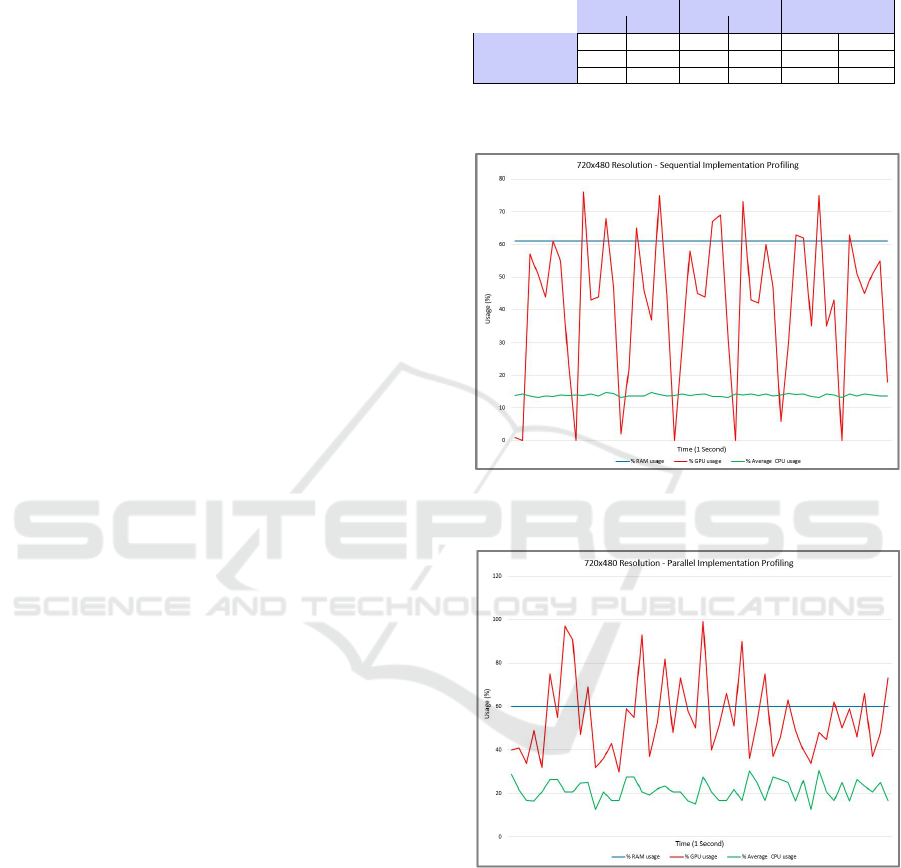
In Figures 5, 6, 7, 8, 9, and 10, we can observe the
hardware consumption within a window of 1 second
Table 2: FPS, capture and process time table. In the first row
we have the different resolutions, ’SEQ.’ refers to sequen-
tial, ’PARL.’ refers to parallel. Process and capture time are
in milliseconds.
Res 720x480 Res 1280x720 Res 1920x1080
SEQ. PARL SEQ. PARL SEQ. PARL
FPS 19.99 25.47 9.99 9.99 4.99 4.99
Process t. (ms) 39.01 38.79 40.69 41.19 42.59 42.41
Capture t. (ms) 10.89 12.07 59.22 99.97 157.30 200.09
with 50 samples and 20 milliseconds between them.
Figure 5: Profiling for 720x480 resolution with sequential
implementation.
Figure 6: Profiling for 720x480 resolution with parallel im-
plementation.
In Figures 5 and 6, we have profiling results for
the 720x480 resolution. Note that there is no GPU
idle time in the sequential implementation, which ob-
tained the highest FPS among all tests. In the sequen-
tial implementation, there are moments of idleness
where the GPU reaches 0% consumption. The aver-
age CPU consumption was also higher in the parallel
implementation.
Figures 7 and 8 show the results of profiling the
1280x720 resolution. Both implementations show
ICEIS 2023 - 25th International Conference on Enterprise Information Systems
560
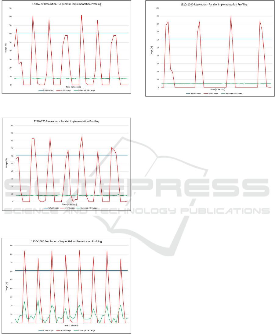
Figure 7: Profiling for 1280x720 resolution with sequential
implementation.
Figure 8: Profiling for 1280x720 resolution with parallel
implementation.
Figure 9: Profiling for 1920x1080 resolution with sequen-
tial implementation.
moments of GPU idleness and similar average CPU
consumption.
Figures 9 and 10 show the results of profiling the
Figure 10: Profiling for 1920x1080 resolution with parallel
implementation.
1980x1080 resolution. Even in the 1280x720 resolu-
tion, there are moments of GPU idleness. The par-
allel implementation was the one with the lowest av-
erage CPU consumption, which indicates the reason
for having the longest capture time among all exper-
iments. The sequential implementation had the most
significant variation in average CPU usage. The aver-
age use of RAM remains the same in all tests. This
use is 61%.
6 CONCLUSIONS
In this work, we present a robot capable of moving
to specific locations in an industrial plant. This robot
applies the Edge AI concept in its architecture. Its
handling is based on a state machine and uses com-
puter vision and feedback control.
The solution employs computer vision to detect
objects representing specific locations in an industrial
plant. This detection happens through the use of a
CNN, more specifically, YOLOv7. After identifying
the local objective, the feedback control works so that
the robot moves to the local objective. The robot was
tested in the laboratory and could perform a move-
ment task in a controlled environment.
The system’s performance test presented here
evaluated image capture and object detection within
three different camera resolutions and with two dif-
ferent implementations, in a sequential and parallel
way. The effects of using different implementations
on object detection performance were presented.
The best result was 25 FPS, with parallel imple-
mentation and 720x480 resolution. This information
shows that YOLOv7 achieves real-time requirements
on Jetson Xavier NX for object detection. Addition-
ally, a profile of the tests was also performed, compar-
Towards Autonomous Mobile Inspection Robots Using Edge AI
561

ing the CPU, RAM, and GPU consumption for each
resolution and type of implementation.
There is a wide range of future work. First, valida-
tion in a real environment can improve the evaluation
of its operation in a more challenging scenario. The
application in mine scenarios, workshops, and ware-
houses is of great value and can bring insights. Based
on sensor fusion, better use of LIDAR can be inte-
grated to achieve fully autonomous navigation where
no movement-related data input will be required. It is
also viable to study the use of other sensors. Finally,
we will apply and validate Reinforcement Learning
and other AI techniques and add probabilities to the
state machine transforming it into Markov Chains to
improve the robot’s functioning.
ACKNOWLEDGEMENTS
The authors would like to thank SASCAR, NVIDIA,
UFOP, CAPES and CNPq for supporting this work.
This work was partially financed by Coordenac¸
˜
ao
de Aperfeic¸oamento de Pessoal de N
´
ıvel Superior
(CAPES) - Finance Code 001, and by Conselho Na-
cional de Desenvolvimento Cient
´
ıfico e Tecnol
´
ogico
(CNPq) - Finance code 308219/2020-1.
REFERENCES
Alatise, M. B. and Hancke, G. P. (2020). A review on chal-
lenges of autonomous mobile robot and sensor fusion
methods. IEEE Access, 8:39830–39846.
Albawi, S., Mohammed, T. A., and Al-Zawi, S. (2017a).
Understanding of a convolutional neural network. In
2017 international conference on engineering and
technology (ICET), pages 1–6. Ieee.
Albawi, S., Mohammed, T. A., and Al-Zawi, S. (2017b).
Understanding of a convolutional neural network. In
2017 International Conference on Engineering and
Technology (ICET), pages 1–6.
Arulprakash, E. and Aruldoss, M. (2022). A study on
generic object detection with emphasis on future re-
search directions. Journal of King Saud University-
Computer and Information Sciences, 34(9):7347–
7365.
Aulinas, J., Petillot, Y., Salvi, J., and Llad
´
o, X. (2008). The
slam problem: a survey. Artificial Intelligence Re-
search and Development, pages 363–371.
Chen, J. and Ran, X. (2019). Deep learning with edge
computing: A review. Proceedings of the IEEE,
107(8):1655–1674.
Cheng, M. and Xiang, D. (2020). The design and applica-
tion of a track-type autonomous inspection robot for
electrical distribution room. Robotica, 38(2):185–206.
Dandurand, P., Beaudry, J., H
´
ebert, C., Mongenot, P.,
Bourque, J., and Hovington, S. (2022). All-weather
autonomous inspection robot for electrical substa-
tions. In 2022 IEEE/SICE International Symposium
on System Integration (SII), pages 303–308. IEEE.
Ebayyeh, A. A. R. M. A. and Mousavi, A. (2020). A review
and analysis of automatic optical inspection and qual-
ity monitoring methods in electronics industry. IEEE
Access, 8:183192–183271.
Florescu, A. and Barabas, S. A. (2020). Modeling and
simulation of a flexible manufacturing system—a ba-
sic component of industry 4.0. Applied sciences,
10(22):8300.
Hassoun, A., A
¨
ıt-Kaddour, A., Abu-Mahfouz, A. M.,
Rathod, N. B., Bader, F., Barba, F. J., Biancolillo, A.,
Cropotova, J., Galanakis, C. M., Jambrak, A. R., et al.
(2022). The fourth industrial revolution in the food
industry—part i: Industry 4.0 technologies. Critical
Reviews in Food Science and Nutrition, pages 1–17.
Hercik, R., Byrtus, R., Jaros, R., and Koziorek, J. (2022).
Implementation of autonomous mobile robot in smart-
factory. Applied Sciences, 12(17):8912.
Ishikawa, S. (1991). A method of indoor mobile robot
navigation by using fuzzy control. In Proceedings
IROS’91: IEEE/RSJ International Workshop on In-
telligent Robots and Systems’ 91, pages 1013–1018.
IEEE.
Krogh, A. (2008). What are artificial neural networks? Na-
ture biotechnology, 26(2):195–197.
Li, E., Zeng, L., Zhou, Z., and Chen, X. (2019). Edge
ai: On-demand accelerating deep neural network in-
ference via edge computing. IEEE Transactions on
Wireless Communications, 19(1):447–457.
NVIDIA (2023). Nvidia jetson xavier nx. Avail-
able in: https://developer.nvidia.com/embedded/learn/
get-started-jetson-xavier-nx-devkit. Accessed on Jan-
uary 14, 2023.
Raspberrypi (2023). Raspberry pi 4 model b. Avail-
able in: https://www.raspberrypi.com/products/
raspberry-pi-4-model-b/. Accessed on January 14,
2023.
Salimpour, S., Queralta, J. P., and Westerlund, T. (2022).
Self-calibrating anomaly and change detection for
autonomous inspection robots. arXiv preprint
arXiv:2209.02379.
Szrek, J., Jakubiak, J., and Zimroz, R. (2022). A mobile
robot-based system for automatic inspection of belt
conveyors in mining industry. Energies, 15(1):327.
Wang, C.-Y., Bochkovskiy, A., and Liao, H.-Y. M. (2022).
Yolov7: Trainable bag-of-freebies sets new state-of-
the-art for real-time object detectors. arXiv preprint
arXiv:2207.02696.
Wang, X., Han, Y., Wang, C., Zhao, Q., Chen, X., and Chen,
M. (2019). In-edge ai: Intelligentizing mobile edge
computing, caching and communication by federated
learning. IEEE Network, 33(5):156–165.
Waveshare (2023). Stepper motor hat v0.1. Available
in: https://www.waveshare.com/wiki/Stepper Motor
HAT. Accessed on January 14, 2023.
YDLIDAR (2023). Ydlidar x2. Available in: https://www.
ydlidar.com/products/view/6.html. Accessed on Jan-
uary 14, 2023.
ICEIS 2023 - 25th International Conference on Enterprise Information Systems
562
