
Simulation Structure for Simulation Model of MCFC–GT Hybrid
System
*
Jarosław Milewski
1a
, Jakub Skibinski
1
and Piotr Biczel
2
1
Institute of Heat Engineering, Warsaw University of Technology, 21/25 Nowowiejska Street, Warsaw, Poland
2
Institute of Electrical Power Engineering, Warsaw University of Technology, 75 Koszykowa Street, Warsaw, Poland
Keywords: Fuel Cells, Hydrogen, Control System, Hybrid System.
Abstract: The control system of MCFC coupled with a gas turbine should be based on the multi–layer structure, (two
or three–layers), wherein the third layer relates to the power output from the system and can be considered
separately. Simulation model of MCFC–GT hybrid system was built. The simulator is based on a zero-
dimensional modelling of the individual elements of the system. The simulator was used for mapping the
main components behaviour (MCFC and GT separately). Based on the obtained maps of the performances
and adopted restrictions on technical–operational nature the operation line for the first line of the control
strategy was obtained. The presented results indicate that the analysed MCFC–GT Hybrid System possesses
a high operation and control flexibility while at the same time maintaining stable thermal efficiency. Operation
of the system is possible over a wide range of parameter changes.
1 INTRODUCTION
Presently, most energy is produced by large baseload
power plants (Kawabata et al., 2012) and distributed
to customers via a grid. In the future the energy
distribution system will probably take a radically
different form—it will be composed of many small
units connected to a network called distribution
generation (DG).
DG is a system of energy distribution where the
energy is produced locally. A connection to the grid
allows energy to be bought from and sold to other
customers. Energy sources for DG will have to meet
certain requirements: appropriate range of power
output, electrical efficiency—which are higher than
presently obtained by large power plants, acceptable
costs of installation, possibility of using standard fuels.
Most of the requirements are met by fuel cell
hybrid systems (HS), which are a combination of
a fuel cell module and gas turbine system and utilized
for power generation, combined heat, and power, and
even triple–generation. Hydrogen is the most
promising energy carrier for future applications.
There are many types of fuel cells, two of them are
high temperature: Molten Carbonate Fuel Cell
a
https://orcid.org/0000-0003-1215-1802
(Ramandi et al., 2014; Razbani and Assadi, 2014;
Sheng et al., 2006; Wee, 2014)—MCFC—and Solid
Oxide Fuel Cell (Ding et al., 2014; Razbani and
Assadi, 2014; Xu et al., 2014) —SOFC. Solid Oxide
Fuel Cells (SOFCs) are potential sources for this
system of energy conversion due to their high
efficiency and possibility of direct use of
hydrocarbons. Moreover, their high working
temperature allows for the possibility of using lower-
cost catalysts (Ni vs. Pt), standard fuels (even
biofuels) and the possibility of adding a gas turbine
subsystem to increase total efficiency.
Control strategy is an important element in
designing any system of this kind and it constitutes
a significant part of the modeling work done. Off-
design (part-load) analysis is an important issue for
any type of system involving MCFC–HS and should
be considered when designing and defining the
operational characteristics. A proper off-design map
of performance underscores control strategy design.
Results drawn from system behavior analysis at part
load conditions should aid in defining the system
structure and its nominal parameters, as well as the
constructional solution and characteristics of a given
subsystem.
*
Paper published in Journal of Fuel Cell Science and
Technology 12(4) DOI:10.1115/1.4031169
202
Milewski, J., Skibinski, J. and Biczel, P.
Simulation Structure for Simulation Model of MCFCâ
˘
A ¸SGT Hybrid System.
DOI: 10.5220/0012052100003546
In Proceedings of the 13th International Conference on Simulation and Modeling Methodologies, Technologies and Applications (SIMULTECH 2023), pages 202-209
ISBN: 978-989-758-668-2; ISSN: 2184-2841
Copyright
c
2023 by SCITEPRESS – Science and Technology Publications, Lda. Under CC license (CC BY-NC-ND 4.0)
Bedont et al. (Bedont et al., 2003) investigated off-
design performance of a hybrid system based on an
existing 100 kW MCFC stack. Chen et al. (Chen et
al., 2006) show that the generating efficiency of the
MCFC-HS ( ≈ 13 kW) is close to 60% at the design
point and over 56% at part load conditions. A few
dynamic response investigations of the MCFC can be
found in (He, 1998; Kang et al., 2001; Sheng et al.,
2006; Yang et al., 2019). The paper (Iora et al., 2010)
presents a model for the off-design analysis of
a hybrid plant based on a MCFC and a gas-turbine.
The model is used to define a possible regulation
strategy for the power plant, minimizing the
performance decay at partial load and allowing
investigation of the interaction issues among the
different plant components. The results indicate the
possibility to effectively regulate the plant power
output acting on the turbine shaft speed, the air-to-
fuel ratio, the bypass of cathode air, and the fuel
utilization, achieving very high part-load efficiency
and respecting constraints on the admitted operating
range for the plant components. In (J Milewski and
Miller, 2012) the results of mathematical modeling
and numerical simulations of the off-design (part-
load) operation of the molten carbonate fuel cell
hybrid system (MCFC-HS) are set out. The governing
equations of modeling are given and an adequate
simulator of the MCFC stack was made and
described. The performance of the MCFC-HS with
part- and over-load operation is shown, and adequate
maps are given and described.
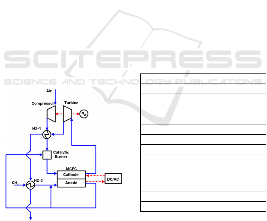
Figure 1: The configuration of MCFC–GT Hybrid System.
In this control strategy study for MCFC-HS, use was
made of methodology and experience of the Institute
of Heat Engineering (Warsaw University of
Technology). Institute of Heat Engineering
methodology was utilized in the mathematical
modeling of the “classic” system elements (e.g.,
compressor, turbine, heat exchanger). HYSYS.Plant
(“HYSYS.Plant Steady State Modelling,” 1998)
software was used for modeling and simulations.
The results presented in this paper concern
a larger system (3 MW), which can be utilized for
office building applications. An axial turbine can
replace the radial turbine for this range of power.
2 MOLTEN CARBONATE FUEL
CELL–GAS TURBINE HYBRID
SYSTEM
The planar MCFC has pre-commercial applications
(100 kW to 2.8 MW) which include the methane–
fueled MCFC Module (MCFC-M) as the main object.
The fuel cell stack, heat exchangers, mixing chamber,
blower, pre-reforming plenum and re-cycle plenum
Table 1: Nominal parameters of the MCFC-GT hybrid
system (Milewski et al., 2010; Jarosław Milewski and
Miller, 2012).
Paramete
r
Value
Overall Efficienc
y
(
LHV
)
, % 58
Re-c
y
cle Facto
r
44
Excess Air Facto
r
1.68
Avera
g
e Cell Volta
g
e, V 0.66
DC/AC inverter efficienc
y
, % 95
Electric
g
enerator efficienc
y
, % 99
Mechanical efficienc
y
of the GT, % 99
Electric motor efficienc
y
, % 95
Turbine Inlet Temperature
(TIT), ○ C
650
Compressor pressure ratio 8.35
Fuel cell electrolyte material Li/Na
Electrolyte matrix thickness, mm 1
are placed inside the MCFC-M. The Molten
Carbonate Fuel Cell—Hybrid System consists of the
following elements:
Simulation Structure for Simulation Model of MCFCâ
˘
A¸SGT Hybrid System
203

• Air Compressor
• Fuel Compressor
• Gas Turbine
• Air Heater
• Fuel Heater
• MCFC Module
The stack consists of parallel, and series
connected cells. The singular cell consists of three
main layers: anode, electrolyte, and cathode. The
electrolyte is kept by a matrix, which provides cell
support. Proper and efficient operation of the MCFC
module requires additional devices.
Process air is delivered to the MCFC at an
elevated temperature and flows through the heat
exchanger. Air then flows through the stack and
escapes on the other side. Finally, it enters the
combustion plenum where the remaining non-
oxidized components are utilized.
Excess power from the compressor turbine
subsystem is converted into electricity. HS efficiency
is given by the equation:
𝜂
𝑃
⋅𝜂
𝑃
𝑃
,
⋅𝜂
⋅𝜂
𝑃
,
𝑛
⋅𝐻𝐻𝑉
where: η —efficiency; g —electric generator; m —
mechanical; C —compressor; n —molar flow,
kmol/s; HHV —Higher Heating Value,
kJ/kmol; DC-AC —DC/AC inverter.
Based on 0 D mathematical modeling the design
point parameters of the system presented in
Fig. 1 were estimated; they were obtained by the
researchers’ own calculations based on an adequate
mathematical model (Milewski et al., 2013). During
the simulation the electrolyte matrix thickness and
electrolyte materials assumed were 1 mm and Li/Na,
respectively. The main system parameters are
presented in Table 1.
3 THE CONTROL STRATEGY
Mathematical modeling is now the basic method for
analyzing systems incorporating fuel cells. A zero-
dimensional approach is used for the modeling of
system elements. Mathematical models of MCFC,
and other system elements as well as the control
strategy for MCFC–GT based on triple–layer control
system is presented in our previous works (Milewski
et al., 2010; Jarosław Milewski and Miller, 2012). As
the results of the previous works adequate maps of
performances were obtained with indicated the
control line of the system. In general, it should be
underlined that in the case of a system with
a pressurized MCFC and gas turbine set there is
a possibility of changing the system power output by
changing not only the amount of fuel but also the
voltage and the MCFC current at variable rotational
speeds of the compressor-turbine unit. This is
accompanied by varying system efficiencies. Hence
there is a need to formulate an appropriate control
concept (control strategy logic) and approach for
technical realization.
Figure 2: Triple-layer control system.
A triple layer control system is proposed for
MCFC-HS operation control. The system consists of
three layers: Control Strategy, Adaptation, and
Regulation (see Fig. 2).
The first layer is responsible for safe and efficient
operation of the whole hybrid system. Adequate
functional relationships between all controlled
parameters and constraints should be applied. The
adaptation layer is responsible for making corrections
to first layer characteristics due to the degradation of
system elements. The last layer of the control system
acts in dynamic mode to realize the control strategy.
The control strategy is based on three functional
relationships:
𝑚
𝑓𝑃
𝑛𝑓𝑃
𝐼
𝑓𝑃
where: P
HS
—is power demanded by an external load.
Approximately, 16,000 system operation points
(state points) were found. Every state point is defined
by three independent parameters: delivered fuel flow,
rotational speed of compressor-turbine subsystem,
and stack current. The other flow and electric
parameters were collected for these three parameters.
This data set was analyzed, and it was found that the
best system performances are obtained at the highest
values of fuel utilization factor. The highest possible
fuel utilization factor was found to be 90%. This
means that fuel flow can be correlated with used
SIMULTECH 2023 - 13th International Conference on Simulation and Modeling Methodologies, Technologies and Applications
204

electric current from the stack by the following
relationships:
𝐼
𝑚
𝑐𝑜𝑛𝑠𝑡
,
𝑎⋅𝑃
𝑏 (1)
,
𝑎⋅𝑃
𝑏 (2)
where: a and b —linear regression factors. The linear
regression factors a and b are: 2.1 ⋅ 10
-4
and 8.69 ⋅ 10
-
2
.
The maps presented below include the values of
parameters for constant fuel utilization factor of 90%.
Adequate maps of performance were generated by
a MCFC–GT Hybrid System simulator using 0 D
mathematical modeling. The operation line of
MCFC–GT Hybrid System was determined based on
in-depth analysis of the maps obtained. The best
performance and safe operation of the system can be
achieved with constant fuel utilization factor (at the
highest possible value). Setting the constant fuel
utilization factor at 90% appears acceptable and
adequate relationships are proposed (1 and 2). Thus,
the obtained relationships are used in the first layer of
the triple layer control system.
The second layer is needed for adaptation of the
control strategy to changes in external environments
(fuel quality, single element degradations, etc.). The
long operation of the MCFC–GT Hybrid System is
not the subject of the paper; thus, this layer remains
empty.
4 THE CONTROL SYSTEM
The third layer of the control system is responsible for
dynamic operation of the system and requires to be
built as the control system of the unit. The control
strategy can be realized based on various
architectures, in this paper we propose to use internal
DC micro network to balance the power between
MCFC stack and gas turbine subsystem.
Figure 3: The general structure of DC/DC converter.
The control system is based on DC/DC
converters, which can be classified in various ways,
but generally they possess the similar structure as
shown in Fig. 3. Two major subsystems can be
distinguished here the power circuit and control
circuit. The heart of the control circuit regulators is
selected signal (voltage, current or power, input or
output, or any combination of these), depending on
the application, and the modulator. Power circuit
consists of an input filter, the encoder system
transformer and rectifier (in some types of converters,
for example in the breastbone) and output filter.
Figure 4: Block scheme of single unit controller.
Figure 5: Texas Instruments TMS320F2812 controller.
Currently control systems for complex circuitry,
such as hybrid systems that use different sources of
energy, the building blocks of the special signal
processors DSP, commercially available controller
(Texas Instruments TMS320F2812—see Fig. 5) was
used. The main tasks of the used controller in the
hybrid system control are:
• measurements of currents and voltages of each
local devices
Simulation Structure for Simulation Model of MCFCâ
˘
A¸SGT Hybrid System
205
• if necessary, modifying the control signal to
ensure constant current–voltage conditions at
the output resulting from the setpoints coming
from the main controller.
• transmission of information on the operation
of the inverter by using external interfaces
• possibility to change the setting operation of
the inverter via the external interface.
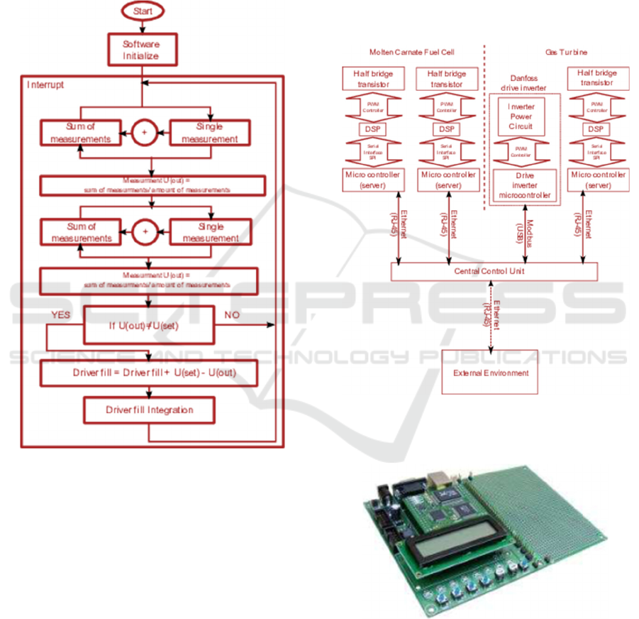
Figure 6: Block scheme of the algorithm implemented in
the single unit controller.
The designed control system was achieved on the
processor TMS320F281 calling the timer interrupt
every 50 microseconds (see Fig. 6). The
discontinuation of this measurement is made,
integration and correction of the width of the
rectangular waveform. This is sufficient because the
frequent measurement gives the ability to quickly
respond to changing output parameters. PWM signal
generation takes place outside the main program. It is
independent of the computational process. Thus,
when conducting the calculation of new settings
waveforms are still generated from a predetermined
frequency—typically 10 .. 30 kHz.
A good idea is also to use multiple interfaces, e.g.
ISP for communication and RJ-45 interface to make
simple changes or reading an information from
master (external) controller, as implemented in
MCFC–GT hybrid system—Fig. 7. The used
microcontroller (TMS320F2812) cannot be
connected in a simple way to Ethernet interface, and
since it is necessary to realize the communication
between CPU to the local actuators, it was decided to
apply additional microcontroller for a web server
function. Fig. 8 presents the view motherboard with
integrated microcontroller ATMEGA 128 carrying
out the functions of the web server.
Figure 7: The structure of the communication between the
MCFC module and gas turbine sub-system by the control
system.
Figure 8: A view of motherboard which integrating
a microcontroller ATMEGA 128 16 MHz with Ethernet
controller RTL1819AS IEEE 802.3 10Mb/s for carrying out
the function of a web server.
The main assumptions designed control system,
using several communication interfaces, standards,
SIMULTECH 2023 - 13th International Conference on Simulation and Modeling Methodologies, Technologies and Applications
206
and protocols (Ethernet, SPI, ModBus) for
communication between components of MCFC-GT
hybrid system are as follows:
• Power electronics inverter control for
simulating MCFC behavior based on signals
from the CPU based on two cooperating
microcontrollers ATMEGA 128 and
TMS320F2812, one of whom one acts as
server and the other is responsible for the
stable operation of the inverter.
• Classic serial interface was used for the
communication between TMS320F2812
and a microprocessor (server). Interface is
relatively simple to use, the amount of
information sent by it will not be large, and
the distance between the two processors will
be the order of centimeters, so there is no
significant risk of interference between the
control signals.
• Gas Turbine subsystem controller is
a microcontroller Danfoss drive, see Fig. 9
• Drivers of power electronic converters
enable parallel operation of both
components (MCFC and gas turbine set) are
based on two cooperating microcontrollers,
one of which acts as a server and the other is
responsible for the stable operation of the
inverter.
• Communication between the central control
unit and the controller of the MCFC and the
driver circuits enable parallel operation is
realized by Ethernet.
• Communication between the central control
unit and the Gas Turbine set controller (drive
inverter) is implemented using the ModBus
protocol.
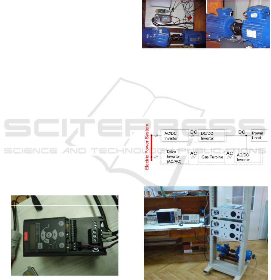
Figure 9: Danfoss drive inverter.
The control system was implemented into software–
hardware simulator of the MCFC–GT hybrid system
which is composed by the following elements:
• two power electronics inverters AC/DC with
half-bridge topology with power 2 kW each
• one power electronics inverter DC/DC with
half-bridge topology with a power of 2 kW
• hardware model of Gas Turbine set
consisting of a three-phase synchronous
motor and three-phase synchronous
generator mechanically connected.
Figure 10: Ga Turbine set hardware–based model with an
inverter drive by Danfoss.
For mapping the MCFC behavior the two power
electronic converters are used, whereby one (AC/DC
converter) simulates the fuel cell and the second
(DC/DC) is responsible for cooperation with the
turbomachinery. The simulating of the air
compressor–gas turbine–generator required the
statement of both machines in the system gas turbine
Figure 11: Scheme of the electric system of the simulator.
Figure 12: The simulator with connected measurements and
data acquisition instrumentation.
set (engine shaft connected to the shaft of the
generator by using a coupling). For powering a model
Simulation Structure for Simulation Model of MCFCâ
˘
A¸SGT Hybrid System
207
of gas turbine set, the Danfoss drive inverter with
a power of 2.2 kW is used—see Fig. Turbine with an
inverter drive the company Danfoss.
The output synchronous generator connected with
the AC/DC inverter is responsible for cooperation
with MCFC. Schematic diagram of the electrical part
of the simulator is shown in Fig. 11. Initially it was
assumed that the system would operate with an
external electric power system, but ultimately limited
to a DC power receiver. Fig. 12 shows the view of the
built simulator with measurements and data
acquisition instrumentation.
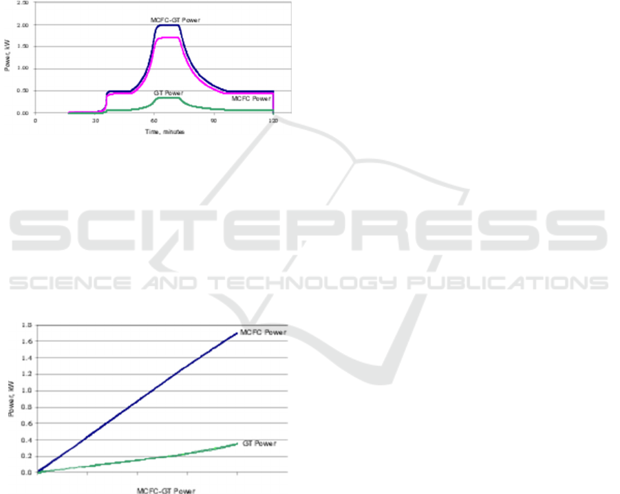
Figure 13: The measured power generated by the system
and the corresponding equipment obtained using the control
system.
The control system and hardware–software
simulator was developed from a series-manufactured
components. The simulator was controlled by the
control system with implemented the control strategy.
Fig. 13 presents the power as a function of time
recorded during the tests under load by the assembled
system.
Figure 14: MCFC and Gas Turbine set powers as functions
of total system power (MCFC–GT).
Fig. 14 presents the dependence of the particular
components that make up the MCFC-GT hybrid
system as a function of output power (compare
against Eqs (1) and (2)). The curves in
Figs 13 and 14 confirm the correctness and validity
of the control strategy carried out, simulation and
constructed mathematical models.
5 CONCLUSIONS
The control system of MCFC coupled with a gas
turbine should be based on the multi–layer structure,
(two or three-layers), wherein the third layer relates
to the power output from the system and can be
considered separately.
Simulation model of MCFC–GT hybrid system
was built. The simulator is based on a zero-
dimensional modeling of the individual elements of
the system. The simulator was used for mapping the
main components behavior (MCFC and GT
separately).
Based on the obtained maps of the performances
and adopted restrictions on technical–operational
nature the operation line for the first line of the control
strategy was obtained. The highest system efficiency
is achieved by working at the highest possible fuel
utilization in the MCFC stack. It was assumed that the
limit value of this parameter is 90%. Adequate
relationships are proposed for achieving this
assumption (see Eqs (1) and (2))—the fuel amount
delivered to the system is in proportion to the amount
of electric current drawn from the MCFC stack.
Maintaining the safe and efficient operation of the
system is realized by gas turbine set in this case, the
gas turbine subsystem, what is obtained by
appropriate changes in the rotational speed of the
shaft.
The control system which realizes the obtained
control strategy was built. Then, hardware-based
models of the main elements were created based on
the electric equipment. The gas turbine was simulated
by coupled electric engine and electric motor
powered by driver inverter. The MCFC was
simulated by programmed micro-controller for giving
current–voltage characteristics. The hardware–
software model was connected to the control system
and adequate simulations were performed.
The presented results indicate that the analyzed
MCFC–GT Hybrid System possesses a high
operation and control flexibility while at the same
time maintaining stable thermal efficiency. Operation
of the system is possible over a wide range of
parameter changes.
The presented control strategy offers some
practical advantages, which include maintaining the
operating point at a possibly high level of efficiency
even under changed operating conditions.
Furthermore, it is possible to separate the overriding
control layer (layer III) from the global strategy of
such a system.
SIMULTECH 2023 - 13th International Conference on Simulation and Modeling Methodologies, Technologies and Applications
208

ACKNOWLEDGEMENTS
This paper was supported by the program Lider grant
nr 0005/L-11/2019 by the National Centre for
Research and Development, Poland.
REFERENCES
Bedont, P., Grillo, O., Massardo, A.F., 2003. Off-design
performance analysis of a hybrid system based on an
existing molten fuel cell stack. J. Eng. Gas Turbines
Power 125.
Chen, Q., Weng, Y., Zhu, X., Weng, S., 2006. Design and
Partial Load Performance of a Hybrid System Based on
a Molten Carbonate Fuel Cell and a Gas Turbine. Fuel
Cells 6.
Ding, J., Li, X., Cao, J., Sheng, L., Yin, L., Xu, X., 2014.
New sensor for gases dissolved in transformer oil based
on solid oxide fuel cell. Sensors Actuators, B Chem.
202, 232–239.
He, W., 1998. Dynamic Model for Molten Carbonate Fuel-
Cell Power-Generation Systems. Energy Convert.
Manag. 39, 775–783.
HYSYS.Plant Steady State Modelling, 1998.
Iora, P., Campanari, S., Salogni, A., 2010. Off-design
analysis of a MCFC-gas turbine hybrid plant.
Kang, B.S., Koh, J.-H., Lim, H.C., 2001. Experimental
study on the dynamic characteristics of {kW}-scale
molten carbonate fuel cell systems. J. Power Sources
94, 51–62.
Kawabata, M., Kurata, O., Iki, N., Tsutsumi, A., Furutani,
H., 2012. Advanced integrated gasification combined
cycle {(A-IGCC)} by exergy recuperation---Technical
challenges for future generations. J. Power Technol. 2,
90–100.
Milewski, J, Miller, A., 2012. Off-design analysis of MCFC
hybrid system. Rynek Energii 151–160.
Milewski, Jarosław, Miller, A., 2012. Triple-layer based
control strategy for molten carbonate fuel cell--hybrid
system. Chem. Process Eng. 445–461.
Milewski, J., Świercz, T., Badyda, K., Miller, A.,
Dmowski, A., Biczel, P., 2010. The control strategy for
a molten carbonate fuel cell hybrid system. Int. J.
Hydrogen Energy 35, 2997–3000.
Milewski, J., Wołowicz, M., Miller, A., Bernat, R.,
RafałBernat, 2013. A reduced order model of molten
carbonate fuel cell: A proposal. Int. J. Hydrogen Energy
38, 11565–11575. https://doi.org/10.1016/j.ijhydene.
2013.06.002
Ramandi, M.Y., Dincer, I., Berg, P., 2014. A transient
analysis of three-dimensional heat and mass transfer in
a molten carbonate fuel cell at start-up. Int. J. Hydrogen
Energy 39, 8034–8047.
Razbani, O., Assadi, M., 2014. Artificial neural network
model of a short stack solid oxide fuel cell based on
experimental data. J. Power Sources 246, 581–586.
https://doi.org/10.1016/j.jpowsour.2013.08.018
Sheng, M., Mangold, M., Kienle, A., 2006. A strategy for
the spatial temperature control of a molten carbonate
fuel cell system. J. Power Sources 162, 1213–1219.
Wee, J.-H., 2014. Carbon dioxide emission reduction using
molten carbonate fuel cell systems. Renew. Sustain.
Energy Rev. 32, 178–191.
Xu, H., Dang, Z., Bai, B.-F., 2014. Electrochemical
performance study of solid oxide fuel cell using lattice
Boltzmann method. Energy 67, 575–583.
Yang, C., Deng, K., He, H., Wu, H., Yao, K., Fan, Y., 2019.
Real-Time Interface Model Investigation for MCFC-
MGT HILS Hybrid Power System. ENERGIES 12.
https://doi.org/10.3390/en12112192.
Simulation Structure for Simulation Model of MCFCâ
˘
A¸SGT Hybrid System
209
