
Model-Based Documentation of Architectures for Cloud-Based Systems
Marvin Wagner and Maritta Heisel
University of Duisburg-Essen, Duisburg, Germany
Keywords:
Cloud-Based System, Metamodel, Method, Cloud System Analysis Pattern, Design Phase.
Abstract:
In recent years, the importance of cloud-based systems highly increased. Users can access these systems
remotely, e.g. for sharing data with others. Furthermore, complete applications can be realized directly in the
web browser. Designing such systems is a challenging task for software architects, which can be supported by
following a model-based approach. The structure of an architectural model can be defined in a metamodel, thus
providing an unambiguous system description. The so created model can not only be used in the subsequent
steps of software development, e.g. during implementation, but also for further analysis of privacy and security
issues. In this context, we provide three contributions in this paper. We first define a metamodel that defines
the semantics of a cloud-based system. We derived the elements from our experience in industrial projects.
Second, we offer a step-wise method to model a cloud-based system. As input, we make use of a pattern that
describes the system’s context. Third, we provide a graphical editor as tool support to assist cloud architects
in applying our approaches.
1 INTRODUCTION
Cloud providers offer state-of-the-art services for pro-
cessing and analyzing massive amounts of data and
offer customers rapid elasticity for their applications.
In the future, cloud-based systems will be even more
in demand, for example for machine learning (Vahdat
and Milojicic, 2021).
From a technical point of view, a cloud architect
designs a cloud-based system in the form of con-
nected applications that use various cloud services
and run on the cloud provider’s platform. The ap-
plications are accessible from the Internet through IP
addresses. In addition, the cloud provider offers ad-
ministrative interfaces for the configuration and man-
agement of cloud services.
A suitable overview of the cloud’s architecture is
required for developing and analyzing cloud-based
systems. Such an overview helps developers to com-
municate with each other. Another advantage is
to clarify in the early development phases whether
the system overview created corresponds to the cus-
tomer’s wishes. Usually, architectures are docu-
mented on the fly, thus leading to ambiguous interpre-
tations of the system under development. To address
this issue, the documentation requires semantic rules
and structured guidance.
With our contributions, we aim to assist cloud ar-
chitects in creating a system overview including the
cloud architecture. As the starting point, we make use
of the Cloud System Analysis Pattern (CSAP) (Beck-
ers et al., 2011) to establish the context of the cloud.
It documents the general structure of the cloud system
and relevant stakeholders that interact with the cloud.
Based on this high-level overview, we propose a step-
wise method to create and document the cloud’s ar-
chitecture. A special focus lies on the interfaces of
the different components and the communication be-
tween them. We make use of a model-based approach
for the documentation. The semantics of the architec-
tural model to be created is formalized with a meta-
model. The metamodel is a further development of re-
search conducted by a collaboration the University of
Duisburg-Essen with Siemens AG. To exemplify the
application of our method and the created model, we
make use of a case study for renting vacation homes.
Additionally, we present validation conditions to en-
sure the correct instantiation of the metamodel.
By providing a graphical editor, we assist archi-
tects in creating the architectural model. It helps to
easily instantiate the metamodel and preserves the de-
fined semantics at the same time.
The remaining sections of our paper are structured
as follows: In section 2, we describe CSAP. In section
3, we present our metamodel, followed by our docu-
mentation method in section 4. Additionally, in this
332
Wagner, M. and Heisel, M.
Model-Based Documentation of Architectures for Cloud-Based Systems.
DOI: 10.5220/0012077800003538
In Proceedings of the 18th International Conference on Software Technologies (ICSOFT 2023), pages 332-344
ISBN: 978-989-758-665-1; ISSN: 2184-2833
Copyright
c
2023 by SCITEPRESS – Science and Technology Publications, Lda. Under CC license (CC BY-NC-ND 4.0)

section we present the example of using our method.
We provide in section 5 for our metamodel validation
conditions. The tool support in form of the graphical
editor is presented in section 6. After that, we discuss
our method and metamodel in section 7. We discuss
related work in section 8 and conclude our work in
section 9 by summarizing our contributions and pro-
viding an outlook on future research directions.
2 CLOUD SYSTEM ANALYSIS
PATTERN (CSAP)
We describe the Cloud System Analysis Pattern
(CSAP) (Beckers et al., 2011) and the method to use
the pattern in this section. The description of CSAP
is needed because our method and the corresponding
metamodel build on it. We further provide an example
instance of the pattern of a rental system for vacation
homes. It serves as the initial input for our method,
which we describe in section 4. The pattern is ap-
plied in the analysis phase of the software develop-
ment lifecycle and provides guidance for context es-
tablishment. It is related to parts of the ISO 27000 se-
ries of standards for information security (ISO, 2018).
CSAP helps the user to systematically perform re-
quirements analysis in the field of cloud computing.
The method to use CSAP consists of three steps and
eleven sub-steps. Also, two templates are provided
for documenting stakeholders. One template serves to
describe direct stakeholders, e.g., the cloud providers.
The other template serves to describe indirect stake-
holders, e.g., legislators or insurances. The templates
consist of the name, description, relations to the cloud
(only in the direct template), motivation, relations
to other stakeholders, assets (only in the direct tem-
plate), compliance, and privacy. Compliance means
that all parties comply with the laws of the respec-
tive states. Privacy means that especially the cloud
provider respects the privacy of the customer. The
cloud provider must comply with the GDPR (General
Data Protection Regulation). By filling in these tem-
plates, we gather knowledge about the stakeholders.
The name is the identifier for the stakeholder, and the
description is used to describe the stakeholder infor-
mally. The relations to the cloud field are used to de-
scribe the inputs and outputs between the stakeholder
and the cloud. The motivation states why the stake-
holder wants use the cloud, e.g. cost reduction. Re-
lations to other stakeholders describe the relation of
the stakeholder to other stakeholders e.g. ”controlled
by” or ”influenced by”. Assets are considered, too.
Assets are valuable items such as the personal data of
a stakeholder, which should be protected by the cloud
provider, if the data is stored or processed by the cloud
provider.
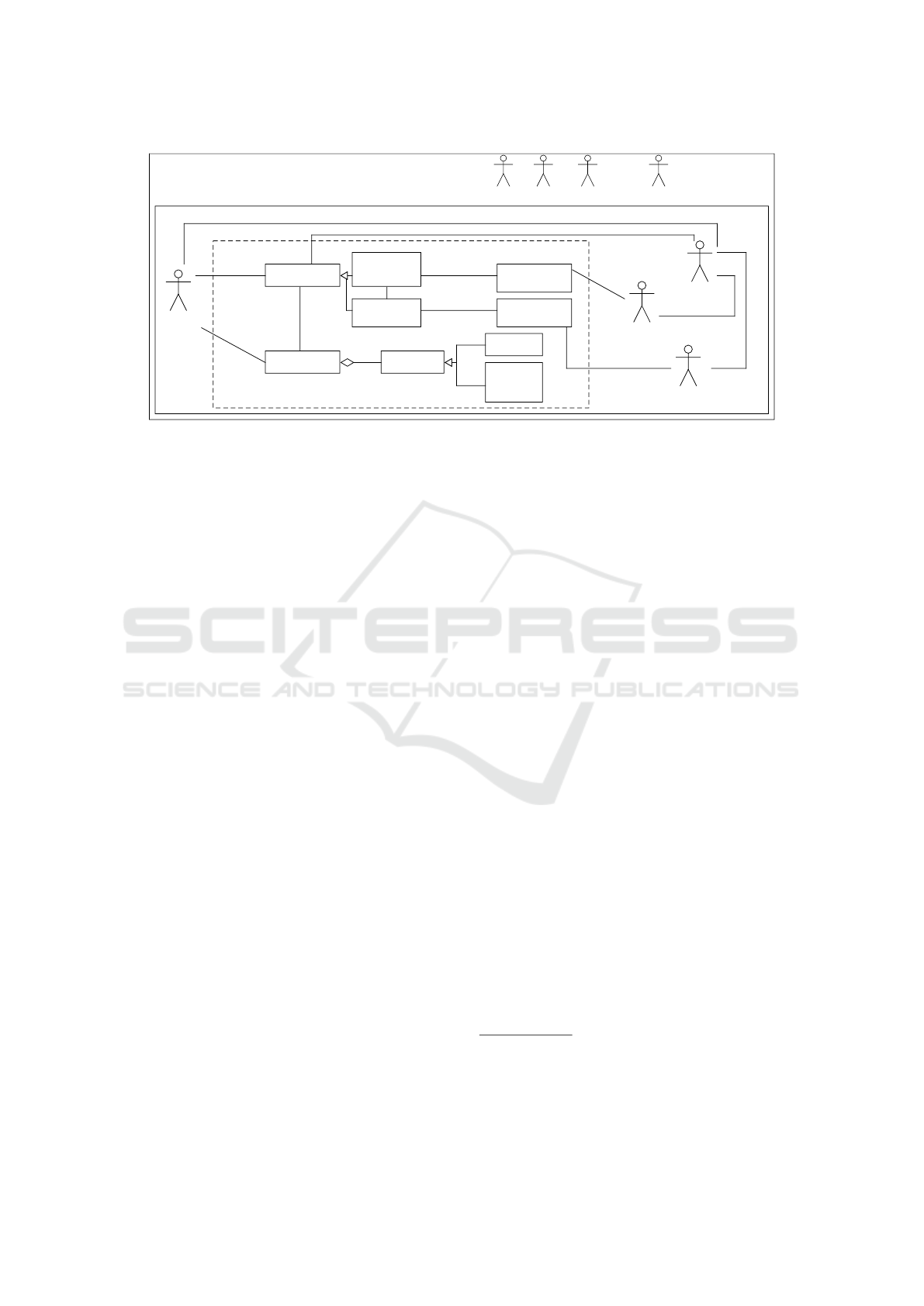
First, we introduce and describe the actors that are
used by the CSAP, see Fig 1. The Cloud Provider
has resources and rents them to Cloud Customer who
wants to provide some service to the End Customer.
Legislators are legal entities such as Germany or the
European Union. Another indirect stakeholder in the
pattern is called Domain, which stands for any stake-
holder that is indirectly involved in the cloud system,
other than as legal entities.
There are three ways of operating cloud systems:
IaaS (Infrastructure as a Service), PaaS (Platform as
a Service), and SaaS (Software as a Service) (Mogull
et al., 2017). IaaS comprises the hardware resources
at some physical location that provide computational
power, storage, or network infrastructure. PaaS pro-
vides deployment platforms, which developers can
use to load and run application code without manag-
ing the underlying resources. Finally, SaaS is defined
as software that is offered by the cloud provider. A
cloud customer rents such software and gets access to
it for example via the internet. Thus, the cloud cus-
tomer needs no extra computational power to use it.
In Figure 1, we show an example instance of the
CSAP. The general structure is defined as follows:
The example uses PaaS, and SaaS which are com-
plemented by VacationRentalSoftware and Personal-
Data. The VacationRentalSoftware is built by the
CloudDeveloper. The PersonalData is related to the
EndCustomer. PaaS, and SaaS are Service(s) which
are provided by a CloudProvider and are based on a
Pool. A Pool is owned by the CloudProvider, and
a Pool consists of Resource(s). Resources can be
Hardware or Software. The CloudDeveloper works
for a CloudCustomer who rents Service(s) from a
CloudProvider. PaaS, SaaS, Service, Pool, Resource,
Hardware, and Software belong to the Cloud it-
self. The CloudProvider, CloudCustomer, CloudDe-
veloper, and EndCustomer belong to the Direct Sys-
tem Environment. Legislator and Domain belong to
the Indirect System Environment.
The method consists of three steps, and the steps
are divided into sub-steps (Beckers et al., 2011).
1. Instantiate the direct system environment
(a) State the instantiations of the cloud stakehold-
ers. We use the step to document the stake-
holders and companies which are involved in
the cloud system to be modeled.
(b) Define further stakeholders for the CSAP. This
step is necessary to document each stakeholder
that is involved.
(c) Instantiate for each direct stakeholder the direct
stakeholder template. The template is available
Model-Based Documentation of Architectures for Cloud-Based Systems
333

in (Beckers et al., 2011). We use the template
to document all relevant information for each
stakeholder.
2. Design the cloud-based system
(a) We use the functional description of a software
to define in which cloud layers (IaaS, PasS, and
SaaS) our software is located in. The cloud lay-
ers are described in (ISO 18384, 2016). Ad-
ditionally, we define the in- and output of the
service(s) and their relation to the direct stake-
holders.
(b) Next, we define the data more precisely. For
this purpose, we can use class diagrams.
(c) We need to provide the geographical location(s)
of the cloud. This is crucial, because we need
to know which legal entities need to be consid-
ered.
(d) Next, we need to decide if the cloud shall be
private, public, or hybrid.
(e) State the technical implementation behind the
system. That means we need to know the re-
quired resources to provide the service(s).
3. Instantiate the indirect system environment
(a) Determine the relevant domains by considering
outsourced processes and determining relevant
legislators. Legislators are countries where the
cloud, users, or provider’s resources are lo-
cated.
(b) Define further indirect stakeholders for the
CSAP, for example legislators.
(c) Instantiate for each stakeholder the indirect
stakeholder template. It is available in (Beck-
ers et al., 2011).
The example instantiation of the CSAP shown
in Figure 1 is the input for our method. We use
stereotypes in our example to clarify the instantia-
tion of the classes from the pattern. The context of
the example is that a Vacation Home Owner wants
to rent his/her vacation homes via an online applica-
tion. That shall happen through a cloud-based sys-
tem. The direct stakeholders are Amazon as Cloud
Provider, VacationOwner as Cloud Customer, Devel-
opment Unit as Cloud Developer, and VacationTenant
as End Customer. We use Amazon as a cloud provider
because it is one of the best known along with Mi-
crosoft Azure. Amazon provides Service and owns
a Pool of Resources. A Resource can be either a
Server or a NetworkAndVirtualizationSoftware. Va-
cationOwner uses PaaS HostVacationRental offerings
to develop, deploy and operate the cloud-based Vaca-
tionRentalService. It is complemented by a Software
Product VacationRentalSoftware. Additionally, the
VacationTenant uses the VacationRentalSoftware as a
SaaS. This is complemented by PersonalData of the
VacationTenant. There are four indirect stakeholders.
Three are of the stereotype Legislator. Those are Ger-
many, the EU (European Union), and the US (United
States). The VacationOwner is German and wants to
provide his/her service in Germany. So, Germany as
Legislator is needed and Germany is a member of the
EU. Also, Amazon is an international company based
in the US. Additionally, the Tax Office is involved,
because the VacationOwner will earn money with the
application.
3 METAMODEL
Our metamodel is provided for structured storage of
the results of our method (see section 4). We use the
Eclipse Modeling Framework (EMF)
1
for the meta-
model (Steinberg et al., 2009). It is an open source
modeling framework which forms the technical ba-
sis for our tool support as described in section 6. We
split the metamodel in three parts: (i) communication
and data, (ii) components and interfaces, and (iii) ser-
vices. Each class in the metamodel has two attributes
for a name and a description. The notation is com-
parable to UML class diagrams (Object Management
Group, 2015). All grey classes are abstract and cannot
be instantiated. Our metamodel contains components,
which have interfaces. We use the terminology of the
standard (ISO 18384, 2016) for the interfaces.
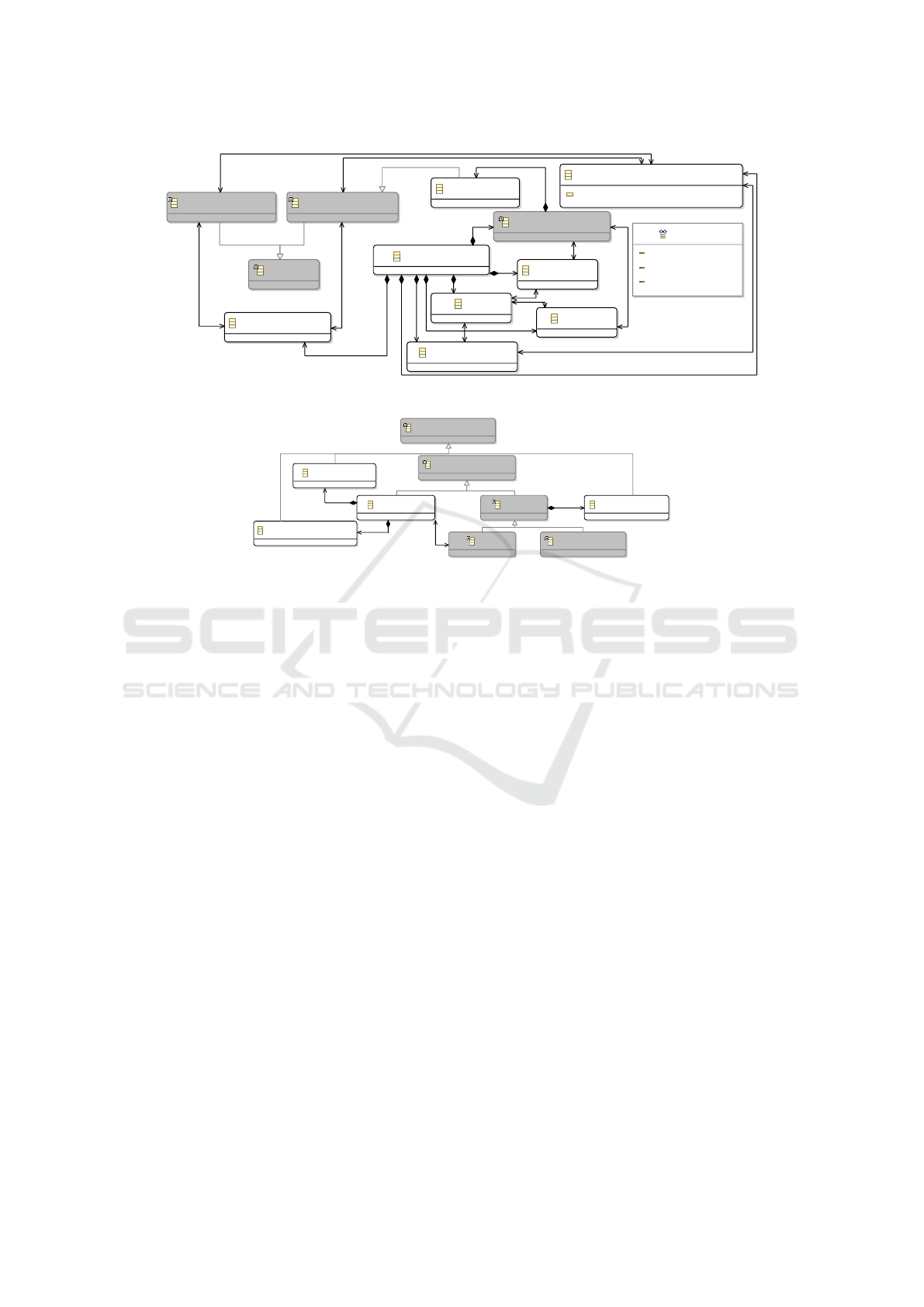
3.1 Communication & Data
We begin with the communication and data model-
ing. Our first class is CloudSystem, see Fig 2. It is
the root element of the metamodel. It contains the
classes Data, VirtualNetworkCommunication, Sub-
networkZone, and CloudComponent. The class Data
has three associations to other classes, which describe
actions on Data. It can be transmittedVia a Virtual-
NetworkCommunication, processedAt a CloudCom-
ponent, and storedAt a CloudComponent. We use
classes for modeling the associations transmittedVia,
processedAt, and storedAt, because there shall be a
possibility to store additional information about the
action. A VirtualNetworkCommunication connects a
RequiredInterface with a ProvidedInterface and the
VirtualNetworkCommunication has a type. We pro-
vide three types: internal, routedViaInternet, other.
At the moment we only have three types to choose
from. The selection is still being expanded, and the
1
EMF - https://www.eclipse.org/modeling/emf/
ICSOFT 2023 - 18th International Conference on Software Technologies
334
1..*
builtBy
worksFor
provides
owns
«Data»
PersonalData
«SaaS»
VacationRental
Service
Indirect System Environment
«Domain»
TaxOffice
«Legislator»
LegilatorUS
«Legislator»
LegislatorEU
«Legislator»
Germany
«CloudCustomer»
VacationOwner
«EndCustomer»
VacationTenant
«CloudDeveloper»
Development Unit
«Cloud
Provider»
Amazon
Cloud
«Software>
NetworkAnd
Virtualization
Software
«Hardware»
Server
«Ressource»
Ressource
Center
«Pool»
Pool
«Software Product»
VacationRental
Software
«Service»
CloudService
«PaaS»
HostVacation
Rental
Direct System Environment
UsedBy
inputBy
/outputBy
1..*
*
isComplementedBy
1..* *
has
1..*
1..*
IsMonitoredBy
*
1..*
has
*
1..*
1..*
*
*
*
1..* 1..*
1..*
1..*
isBasedOn
1..*
1..*
isComplementedBy
1..* *
Figure 1: Example Instantiation of CSAP.
corresponding queries as to whether the types are
valid are still being developed. We need these for later
validation conditions. The type internal is used when
the source and the target of VirtualNetworkCommu-
nication are both inside the cloud system, which we
model. The type routedViaInternet is used when
there is a VirtualNetworkCommunication outside our
cloud system between the source and the target of the
VirtualNetworkCommunication, for example, when a
client accesses the cloud system from outside. Inter-
face is the supertype of RequiredInterface and Pro-
videdInterface. An OutgoingPort has the supertype
RequiredInterface and is part of a CloudComponent.
It is used to show that a VirtualNetworkCommunica-
tion starts at that CloudComponent. A ProvidedIn-
terface denotes the receiver of that communication.
ProvidedInterface(s) and RequiredInterface(s) can be
assigned to a SubnetworkZone.
3.2 Components & Interfaces
In this part of the metamodel we refine the two classes
CloudComponent and ProvidedInterface. CloudCom-
ponent is supertype of the classes Application and
Service. An Application has two types of interfaces:
ApplicationInterface, for example APIs (Application
Programming Interfaces), and UserInterface. Both
interfaces have the supertype ProvidedInterface. A
Service contains a ConfigInterface. It used to config-
ure the Service. Furthermore, Service is the supertype
of Host, and SpecificService.
3.3 Services
The last part of the metamodel is shown in Fig 4. It
defines the classes SpecificService and Host. Virtual-
Machine, ContainerCluster, and GenericHost have
the supertype Host. We derived these three types from
AWS (Amazon Web Services)
2
and Azure
3
. With a
VirtualMachine, the cloud provider provides a run-
ning instance of a virtual machine e.g. Amazon EC2
or Azure Virtual Machine. Typically, cloud providers
provide the option to configure the automated scal-
ing of machine instances. Alternatively, applications
are deployed into containers, which use OS (operat-
ing system)-level virtualization to provide indepen-
dent, small runtime environments. Another host is a
ContainerCluster (Amazon ECS, Azure Kubernetes
Service). ContainerClusters are similar to virtual ma-
chines, but the architecture is different. Container-
Cluster(s) have benefits such as increased ease and
efficiency of container image creation, and cloud and
OS distribution portability
4
. The third and last type of
a Host is GenericHost. It covers all host types except
virtual machine and container cluster. It can be also
used if it is not important which host type is needed
to solve a problem.
CentralService and InstantiatedService have the
supertype SpecificService. We derived them from
AWS and Azure, too. Prominent examples for Cen-
tralServices are AWS S3 and Azure Blob Storage,
object storage services for which system owners can
buy storage space, and configure its accessibility.
The main purpose of Blob Storages is to store mas-
sive amounts of unstructured data. Unstructured data
means that the data has no underlying model or defi-
nition.
5
A database as a service is one example of an
InstantiatedService. Both binds of service have their
own interface types CentralServiceInterface and In-
2
https://aws.amazon.com/
3
https://azure.microsoft.com/en-us/
4
https://kubernetes.io/docs/concepts/overview/
5
https://docs.microsoft.com/en-
us/azure/storage/blobs/storage-blobs-introduction
Model-Based Documentation of Architectures for Cloud-Based Systems
335
CloudSystem
OutgoingPort
CloudComponent
VirtualNetworkCommunication
type : VNCTypes = internal
SubnetworkZone
VNCTypes
internal
other
routedViaInternet
Interface
Data
RequiredInterface
ProvidedInterface
storedAt
processedAt
transmittedVia
Figure 2: Metamodel: communication & data.
ConfigInterface
ApplicationInterface
UserInterface
Application
CloudComponent
Service
SpecificSer vice
Host
ProvidedInterface
Figure 3: Metamodel: components & interfaces.
stantiatedServiceInterface. Both such interfaces are
used to communicate with these services.
4 METHOD
We now present our method to model architectures
for cloud-based systems. We use an instantiation of
CSAP (see Section 2) as input for our method. The
method consists of six steps. Our method enables
the architect to obtain a detailed technical view of
the cloud-based system in form of a model, which
is based on our metamodel as described in section 3.
The abstraction level is lower than in CSAP.
In the following, we describe each step of the
method in detail and apply it to our vacation rental
case study, using the CSAP Vacation Rentals example
from Fig 1 as input. We instantiate the classes of the
metamodel and provide questionnaires for some steps
that aid the architect in selecting metamodel elements.
The results are presented as UML composite structure
diagrams (Object Management Group, 2015).
4.1 Step 1: Create Hosts and Specific
Services
Description. The aim of this step is to create in-
stance(s) of the types Host and/or SpecificService.
Different types of Host and SpecificService are de-
scribed in section 3. First, we take a look at the input
CSAP. Then, we create for each element of the stereo-
type PaaS in our architecture an instance of Host or
SpecificService. For this, we may need additional in-
formation to find the best fitting type. The Host(s) and
SpecificService(s) are represented by a UML Com-
posite Structure Component with the corresponding
stereotype.
Questionnaire. We provide for this step a question-
naire for the architect to decide the type of the PaaS.
• Should the PaaS rely on an existing service
(database, etc.) from the cloud provider?
– Yes → Should a CentralService or an Instanti-
atedService be used?
*
CentralService → Instantiate a CentralSer-
vice.
*
InstantiatedService → Instantiate an Instanti-
atedService.
– No → Should ContainerCluster be used?
*
Yes → Instantiate a ContainerCluster.
*
No → Should a VirtualMachine be used?
· Yes → Instantiate a VirtualMachine.
· No → Instantiate a GenericHost.
Example. In our example, we use Fig 1 as our input.
The result of this step is shown in Fig 5. We have one
element of the stereotype PaaS with the name Host-
VacationRental in our example. We want a simple
ICSOFT 2023 - 18th International Conference on Software Technologies
336

InstantiatedServiceInterface
ConfigInterface
Service
HostConfigInterface
SpecificService
Host
VirtualMachine
ContainerCluster
GenericHost
CentralService
InstantiatedService
CentralServiceInterface
ProvidedInterface
Figure 4: Metamodel: platform services.
«VirtualMachine»
VRVirtualMachine
Figure 5: Result of Step 1.
virtual machine to host our vacation rental software.
So, we create for that element an instance of the type
VirtualMachine with the name VRVirtualMachine in
our architecture. We choose an instance of Virtual-
Machine, because it fits best on the basis of the ques-
tionnaire.
4.2 Step 2: Create Applications
Description. In the second step, we create for each el-
ement of the stereotype SaaS in the CSAP at least one
Application in our metamodel instance. Sometimes a
software consists of multiple applications. For that,
we take a look at our CSAP instance and create an-
other instance of Application if needed. If the Appli-
cation is a self-created software, it needs to run on a
Host. Hence, we may add an association between the
new Application and a Host with the label runsOn.
An Application is represented by a UML Composite
Structure Component with the stereotype Application.
Questionnaire. We provide questions which guide
the software architect through the choices of the host
types for the application.
• Is the application self-created?
• Yes → Which host type shall be used for it?
– Virtual Machine → Create a VirtualMachine
and create a relation to from the Application to
VirtualMachine with the label ’runsOn’.
– ContainerCluster → Create a ContainerClus-
ter and create a relation to from the Application
to ContainerCluster with the label ’runsOn’.
– GenericHost → Create a GenericHost and cre-
ate a relation to from the Application to Generic
with the label ’runsOn’.
• No → Go to step 3.
«Application»
VacationRental
Software
«VirtualMachine»
VRVirtualMachine
runsOn
Figure 6: Result of Step 2.
Example. In our example, we have one SaaS. Hence,
we create one instance of Application with the name
VacationRentalSoftware. It is self-created software.
Hence, we add an association between Vacation-
RentalSoftware and VirtualMachine. The result of
this step for our example is shown in Fig 6.
4.3 Step 3: Derive Data Storages
Description. In the third step, we derive the neces-
sary Data Storages from the CSAP instance. For this,
we create for each Data in the CSAP instance an in-
stance of InstantiatedService or CentralService in our
metamodel instance. In addition, we derive additional
data storages from the context of the cloud-based sys-
tem.
Questionnaire. We provide questions that guide the
software architect through the choices of the different
types of data storages. Depending on which technol-
ogy or service will be used for storage, a CentralSer-
vice or an InstantiatedService can be selected. This
depends entirely on the cloud provider. A CentralSer-
vice is mainly managed by the cloud provider and the
InstantiatedService is not.
• Is there any other data that is needed that does not
appear in the CSAP instance for the final product
to work or that should be used?
– Yes → Should a CentralService or an Instanti-
atedService be used?
*
CentralService → Create an additional Cen-
tralService for that data. Repeat until all data
is recorded.
*
InstantiatedService → Create an additional
InstantiatedService for that data. Repeat until
all data is recorded.
– No → Go to the next question.
Model-Based Documentation of Architectures for Cloud-Based Systems
337

«InstantiatedService»
EndUser
Storage
«InstantiatedService»
VacationRental
Storage
Figure 7: Result of Step 3.
• Should a CentralService or an InstantiatedService
be used to store the data?
– CentralService → Instantiate a CentralService.
– InstantiatedService → Instantiate an Instanti-
atedService.
Example. The result of this step is shown in Fig
7. The instantiated CSAP contains one instance of
Data ’Personal Data’ explicitly. Therefore, we cre-
ate an instance of InstantiatedService with the name
’EndUserStorage’. We can derive a second Data Stor-
age. The cloud-based system needs additional data
about the rental houses. Hence, we create a second
instance of an InstantiatedService and name it ’Va-
cationRentalStorage’ where all information about the
vacations homes are stored. We choose an Instan-
tiatedService, because Amazon AWS and Microsoft
Azure provides several solutions for databases.
4.4 Step 4: Create Interfaces and
Connections
Description. The difference between an Interface
and a VirtualNetworkCommunication is that an inter-
face provides interaction possibilities with a compo-
nent, where as a VirtualNetworkCommunication uses
two interfaces. In this step, we create instances of in-
terfaces and network communications. For this, we
combine the outputs of steps 2 and 3. Each Cloud-
Component can have several interface types, because
of the inheritance to the sub-classes. The types are
named in Figures 3 and 4. We take a look at the
CloudComponents which we instantiated in the last
three steps and derive from the CSAP and additional
knowledge from the system description the necessary
interfaces to communicate with other CloudCompo-
nents. Additionally, the CloudComponent(s) need
OutgoingPort(s) to establish a VirtualNetworkCom-
munication. The OutgoingPort(s) are represented in
our example as UML Composite Structure Socket,
and the ProvidedInterface(s) are represented as UML
Composite Structure Lollipop. Each Service needs a
ConfigInterface, and each Host needs a HostConfig-
Interface. Both are needed to configure the Service
and/or the Host. CentralService and InstantiatedSer-
vice need at least one ProvidedInterface to use the
Service. Depending on the type of ProvidedInterface
and the network zones to which the ProvidedInterface
has been assigned, different types can be selected for
the VirtualNetworkCommunication.
Questionnaire. We provide questions that aid the ar-
chitect to decide the type of ProvidedInterface. Ap-
plications need at least one ProvidedInterface(s).
• Does the Application need an ApplicationInter-
face for configuration or to provide access to it-
self for other Applications or a UserInterface to
provide access for EndUser(s) or DevelopmentU-
nit?
– ApplicationInterface → Instantiate Applica-
tionInterface.
– UserInterface → Instantiate UserInterface.
• Does the Application need additional Application-
Interface(s) or UserInterface(s)? The question
can be repeated as often as you like.
– ApplicationInterface → Instantiate Applica-
tionInterface.
– UserInterface → Instantiate UserInterface.
• Does the CloudComponent need a RequiredInter-
face?
– Yes → Instantiate OutgoingPort
Example. The result of this step is shown in Fig 8.
In our example, we do not annotate the Outgoing-
Port(s) and VirtualNetworkCommunication(s) for rea-
sons of overview and readability. We need Provided-
Interfaces and two OutgoingPorts: Both Instantiated-
Services EndUserStorage and VacationRentalStorage
need one ConfigInterface and one InstantiatedServi-
ceInterface. The ConfigInterfaces are needed to con-
figure the InstantiatedService, in our case databases.
Furthermore, they need the InstantiatedServiceInter-
face to provide the data to other CloudComponent.
The VirtualMachine needs one HostConfigInterface.
It provides the possibility to configure the VirtualMa-
chine, and it offers the possibility to configure the Ap-
plication, which is running on a Host. Finally, the Ap-
plication needs one Interface and two OutgoingPorts
which are needed to communicate with the Instantiat-
edServices. The ProvidedInterface is a UserInterface.
It is needed so that a user, in our case the EndCus-
tomer, can interact with the Application.
4.5 Step 5: Create Data
Description. In the fifth step, we create the instances
of Data and their relations to CloudComponents and
VirtualNetworkCommunications. The relations can
have the stereotypes processedAt, storedAt, and trans-
mittedVia. We do not get all necessary information
from the instantiated CSAP. Therefore, we need addi-
tional information from the cloud-based system de-
scription, about what data shall be handled by the
ICSOFT 2023 - 18th International Conference on Software Technologies
338

«UserInterface»
UserInterfaceApp
«HostConfigInterface»
ConfigManagInterface
«InstantiatedServiceInterface»
StorageVacInterfaceDev
«InstantiatedServiceInterface»
StorageEndUsterInterfaceDev
«InstantiatedService»
EndUser
Storage
«InstandtiatedService»
VacationRental
Storage
«Application»
VacationRental
Software
«VirtualMachine»
VRVirtualMachine
«ConfigInterface»
BuiltInConfigEnUsInterface
«ConfigInterface»
BuiltInConfigVacInterface
runsOn
Figure 8: Result of Step 4.
cloud-based system. We may have to go back to step
3 if we realize that we have forgotten some data stor-
age. The Data is represented by a black-edged rectan-
gle with the stereotype Data and not by a UML Com-
posite Structure Component. Moreover, we represent
the processedAt, storedAt, transmittedVia by a dashed
line, which is not the same as a dependency.
Questionnaire. We provide questions that aid the ar-
chitect to decide, if Data need relations to CloudCom-
ponent(s) and/or Interface(s). The questionnaire has
to be processed for each Data instance.
• Is the Data processed at a CloudComponent?
– Yes → Create one processedAt relation be-
tween the Data and the CloudComponent. Re-
peat until all processedAt(s) are found.
– No → Go to the next question.
• Is the Data stored at a CloudComponent?
– Yes → Create one storedAt relation between the
Data and the CloudComponent. Repeat until all
storedAt(s) are found.
– No → Go to the next question.
• Is the Data transmitted via a VirtualNetworkCom-
munication?
– Yes → Create one transmittedVia relation be-
tween the Data and the VirtualNetworkCommu-
nication. Repeat until all transmittedVia(s) are
found.
– No → Finished.
Example. The result of that step for our example
is shown in Fig 9. In our example, we can derive
PersonalDataOfAnEndUser directly from the CSAP.
From the context of our example, we know that we
handle additional data of the vacation houses Vaca-
tionData. PersonalDataOfAnEndUser is processe-
dAt the VacationRentalSoftware and is transmittedVia
the UserInterfaceApp and the StorageEndUserInter-
face. VacationData is processedAt VacationRental-
Software. Also, it is transmittedVia StorageVacInter-
face and it is storedAt VacationRentalStorage.
4.6 Step 6: Split Interfaces and
Components into Sub-Network
Zones
Description. In the last step, we create Subnetwork-
Zone(s). Interface(s) and OutgoingPort(s) can be as-
signed to one SubnetworkZone. The information for
this step is not included in the CSAP. So, we need
additional information about how the system shall be
structured in SubnetworkZone(s). Two Interface(s) of
the same CloudComponent can be in different Sub-
networkZone(s), because a CloudComponent can act
as firewall or as router. The SubnetworkZone is repre-
sented by a rectangle with a thick black border.
Example. In our example, we need only one Subnet-
workZone because it is a small cloud-based system. It
is named CompanyZone.
The final output of our method is an architecture
with data for our cloud-based system (see Figure 10).
5 VALIDATION CONDITIONS
To make sure that the developed cloud architecture
makes sense, we have defined a number of valida-
tion conditions (VCs). If such a condition is not ful-
filled by the model, a semantic error is present, and
the model should be revised. Our validation condi-
tions are executed on our metamodel, which is imple-
mented in Eclipse Modeling Framework (EMF). The
majority of the validation conditions are implemented
in our tool. One Validation conditions marked with •
needs to demonstrated manually by the architect.
1. Each element needs a name.
2. Each element needs a description.
3. A CloudSystem needs to contain at least one
CloudSystemComponent.
4. Each CloudSystemComponent needs at least one
ProvidedInterface.
5. Each Application runs at least on one Host.
6. Each VirtualNetworkCommunication has exactly
one ProvidedInterface and one RequiredInterface.
7. Each SubnetworkZone needs to contain at least
one ProvidedInterface or RequiredInterface.
8. Each VirtualNetworkCommunication needs a
type.
Model-Based Documentation of Architectures for Cloud-Based Systems
339

«storedAt
«transmittedVia»
««InstantiatedServiceInterface»>
StorageVacInterface
«UserInterface»
UserInterfaceApp
«processedAt»
«trans
mitted
Via»
«InstantiatedServiceInterface»
StorageEndUserInterface
«InstantiatedService»
EndUser
Storage
«InstantiatedService»
VacationRental
Storage
«Data»
VacationData
«Data»
PersonalData
OfAnEnduser
«Application»
VacationRental
Software
«VirtualMachine»
VRVirtualMachine
«transmittedVia»
«stored
At»
«Config
Interface»
BuiltInConfigEndUserInterface
«Config
Interface»
BuiltInConfigVacInterface
«processed
At»
«HostConfigInterface»
ConfigManagInterface
runsOn
Figure 9: Result of Step 5.
«UserInterface»
UserInterfaceApp
«transmittedVia»
«processedAt»
«processedAt»
«storedAt»
«trans
mitted
Via»
«stored
At»
«InstantiatedServiceInterface»
StorageEndUserInterface
«InstantiatedService»
EndUser
Storage
«InstandtiatedService»
VacationRental
Storage
«SubNetworkZone»
CompanyZone
«Data»
VacationData
«Data»
PersonalData
OfAnEnduser
«Application»
VacationRental
Software
«VirtualMachine»
VRVirtualMachine
«transmittedVia»
«Config
Interface»
BuiltInConfigEnUsInterface
«Config
Interface»
BuiltInConfigVacInterface
«InstantiatedServiceInterface»
StorageVacInterface
«HostConfigInterface»
ConfigManagInterface
runsOn
Figure 10: Final Result of our Method.
9. Each Interface of the types ApplicationsInter-
face, HostConfigInterface, ConfigInterface, Cen-
tralServiceInterface, and InstantiatedServiceIn-
terface needs to be used through one connection.
10. Each CloudSystem contains at least one SubNet-
workZone.
11. Each Data has at least one association stored, pro-
cessed, or transmitted.
12. For each end user of the CSAP must exists at least
one UserInterface. •
13. The source and target CloudSystemComponent of
a VirtualNetworkCommunication need to be dif-
ferent.
14. For each PaaS of the CSAP must exist, at least one
Host.
15. A UserInterface shall not be used from a Cloud-
Component.
16. Each Application needs a ProvidedInterface.
17. The ProvidedInterface of an Application needs to
be part of a SubnetworkZone.
18. An end user shall not have access to a HostCon-
figInterface.
19. An end user shall not have access to a ConfigIn-
terface.
20. An end user shall not have access to an Applica-
tionInterface.
21. An end user shall not have access to an Cen-
tralServiceInterface.
22. An end user shall not have access to an Instantiat-
edServiceInterface.
23. Each PlatformService needs at least one Config-
Interface.
24. Each Host needs at least one HostConfigInterface.
These validation conditions can not guarantee the
appropriateness of the cloud architect, but ensure its
internal consistency.
ICSOFT 2023 - 18th International Conference on Software Technologies
340

6 TOOL SUPPORT
To assist software architects in using our method, we
provide a graphical editor for modeling a system’s ar-
chitecture. It is based on the Eclipse Modeling Frame-
work (EMF) (Steinberg et al., 2009) and Sirius
6
. Sir-
ius builds on EMF and the Acceleo Query Language
(AQL). AQL is a specification language similar to
OCL
7
. It is used to work with EMF metamodels. The
elements can be filtered, created, deleted, and ma-
nipulated with AQL. All technologies are realized as
Eclipse plugins and are available open-source. In the
following, we describe the main components of the
editor, as well as its graphical user interface.
Our editor mainly consists of the following three
elements:
Metamodel. The metamodel is realized as an Ecore
model. Ecore is a part of EMF. It defines the se-
mantics for any architecture model that can be cre-
ated with our graphical editor by restricting the
elements to be created, as well as the relations
that can be modeled between them, as described
in section 3. It is part of the editor’s backend. The
metamodel is not visible for the user of the tool.
Model Instance. Each model instance is an instance
of the metamodel and describes a cloud-based
system. It contains all CloudComponent(s), In-
terface(s), and VirtualNetworkCommunication(s)
of a concrete system. The instance can be created
and modified via the graphical user interface of
our editor. Furthermore, the editor allows storing
the results of the modeling process persistently.
The model instances are part of the backend, too.
Graphical Representation. Model instances can be
represented in a user-friendly way, as an archi-
tecture diagram. We implemented different work
flows in our tool to create and modify model ele-
ments based on the graphical representation. The
work flows and diagram elements are defined in
a so-called Viewpoint Specification, which forms
the basis for the user interface. Furthermore, the
Viewpoint Specification ensures consistency be-
tween model instances and the graphical repre-
sentation. We use in the editor our own notation
with boxes for the elements. Figure 11 presents
a screenshot of our editor. The shown dialog is
for creating an instance of an InstantiatedService.
The graphical representation is our front end.
The support tool is in a prototype stage. The sup-
port tool and the questionnaires guide the architect
through the modeling process of a cloud-based system
6
Sirius - https://www.eclipse.org/sirius/
7
https://www.omg.org/spec/OCL/2.4/PDF
based on our method. All required documentation can
be created with the tool. We provide dialogs to create
the different model elements along with the required
attributes. Additionally, the support tool preserves the
semantics of our metamodel. The validation condi-
tions of section 5 can be checked at any time. Sir-
ius provides the possibility for architects to start the
check. 23 validation conditions can be checked auto-
matically while creating an element of the metamodel
in the editor.
With the tool, we provide the possibility to de-
velop, store, check, and evolve cloud system archi-
tectural descriptions.
7 DISCUSSION
In this section, we summarize the advantages of using
our method and the metamodel. The method docu-
ments the architecture for a cloud system. At all, it
is the preparatory step for deeper analyzing the cloud
system.
The documentation includes relevant components,
interfaces, and communications. It can be used by the
architects establish a common understanding of the
cloud system and they can discuss the further process
of the development of a cloud system.
Additionally, the documentation can be used to
analyze possible security problems. For this, it is nec-
essary to develop a taxonomy, which defines possible
attack types for the different interfaces of our meta-
model. Then, an automatic method can be executed to
identify for each interface the attack surface. Further-
more, the metamodel can be extended with treatments
to close or minimize the attack surface. The security
analysis can be supported with validation conditions,
too.
Since we also present data in our documentation,
and these can be deemed relevant for privacy, we can
directly identify which parts of the cloud system come
into contact with this data. We can extend the graphi-
cal editor for privacy aspects. Then, the architect can
determine for each data the component relevant for
privacy.
8 RELATED WORK
Ma et al. (Ma et al., 2017) propose a security view and
presentation of security-related information which are
required for cyber-physical production systems. They
use the reference architecture model RAMI 4.0. The
paper discusses how to represent a system description
with architectural artifacts in RAMI 4.0 and how to
Model-Based Documentation of Architectures for Cloud-Based Systems
341

Figure 11: Example Dialog of our Editor.
extend the modeled architectural artifacts to include
security. Similar to our approach, the viewpoint can
be used to analyze security and its application is sup-
ported by a tool. RAMI 4.0 does not provide as de-
tailed description possibilities as our metamodel.
Maidl et al. (Maidl et al., 2019) provide a meta-
model for cyber-physical systems. That metamodel
has a similar structure to our metamodel but only con-
siders cyber-physical systems. The authors use sev-
eral components and interfaces types in their meta-
model. The model is well defined but not sufficient
for cloud-based systems. We define a metamodel for
cloud-based systems and introduce a method to use it
systematically. A method for the instantiation of their
metamodel is not given by Maidl et al.
There are collections of several architectural pat-
terns addressing specific cloud and virtualization
functionalities (Fehling, 2014; Erl et al., 2015), which
provide a detailed view of specific functionalities.
Those patterns can serve as an extension for our meta-
model to provide more details about the cloud-based
system. The patterns in the books do not provide a
detailed metamodel to instantiate.
Rest Assured
8
was a project of the European
Union’s Horizon 2020 research and innovation pro-
gram. The main goal of that project was to deliver
end-to-end cloud architectures and methodologies for
assuring secure data processing in the cloud. The
project has several publications about cloud-based
systems. The public deliverables of the project in-
clude a high-level architecture for a cloud-based sys-
tem. Our metamodel provides a more technical view
on a cloud-based system, including interfaces and
their types.
Syed and Fern
´
andez (Syed and Fernandez, 2017;
Syed and Fernandez, 2015) provide patterns with a
8
https://restassuredh2020.eu/publications/
special focus on containers, their structure, and their
execution environment. The patterns presented in
these papers can be used to model the infrastructure
between the containers. In contrast to our metamodel,
they concentrate on the container, whereas a Contain-
erCluster is only a part of our metamodel. The pat-
terns can be used to refine our ContainerCluster in
more detail.
Sousa et al. (Sousa et al., 2018a; Sousa et al.,
2018b) propose several patterns for engineering soft-
ware for the cloud. For instance, the authors propose
a pattern for continuously monitoring the system as
a black box. These patterns can be used to provide
other abstraction layers on cloud-based systems that
have been modeled with the presented pattern. Also,
the patterns can be used for our metamodel to con-
sider more abstraction layers.
Fern
´
andez et al. (Fern
´
andez et al., 2016) describe
patterns to model ecosystems of clouds. The patterns
allow considering security aspects, as well. Currently,
the presented patterns focus on details of one specific
platform instance. Especially with regard to cloud
platforms and their shared resources, it is essential
to consider dependencies on other clouds. Therefore,
combining the patterns can provide important infor-
mation for analyzing the security of a cloud-based
system. The output of our method can be used as in-
put for their pattern analysis.
Afzal and Piadehbasmenj (Afzal and Piadehbas-
menj, ) present several architectures for Model-based
testing (MBT). They use AWS as a cloud provider and
GraphWalker as an MBT tool. In relation to our meta-
model, they focus on testing which is not included in
our metamodel or method. Additionally, our meta-
model provides a more detailed view of cloud-based
architecture.
Nkenyereye et al. (Nkenyereye et al., 2020)
present architectures, applications, and virtual ma-
ICSOFT 2023 - 18th International Conference on Software Technologies
342

chine migration for vehicular cloud networks. They
also provide a detailed comparison of existing frame-
works in software-defined vehicular cloud networks.
Their architectures focus on vehicle cloud-based sys-
tems. In contrast we consider cloud-based systems in
general.
9 CONCLUSION
Ma et al. (Ma et al., 2017) propose a security view and
presentation of security-related information which are
required for cyber-physical production systems. They
use the reference architecture model RAMI 4.0. The
paper discusses how to represent a system description
with architectural artifacts in RAMI 4.0 and how to
extend the modeled architectural artifacts to include
security. Similar to our approach, the viewpoint can
be used to analyze security and its application is sup-
ported by a tool. RAMI 4.0 does not provide as de-
tailed description possibilities as our metamodel.
Maidl et al. (Maidl et al., 2019) provide a meta-
model for cyber-physical systems. That metamodel
has a similar structure to our metamodel but only con-
siders cyber-physical systems. The authors use sev-
eral components and interfaces types in their meta-
model. The model is well defined but not sufficient
for cloud-based systems. We define a metamodel for
cloud-based systems and introduce a method to use it
systematically. A method for the instantiation of their
metamodel is not given by Maidl et al.
There are collections of several architectural pat-
terns addressing specific cloud and virtualization
functionalities (Fehling, 2014; Erl et al., 2015), which
provide a detailed view of specific functionalities.
Those patterns can serve as an extension for our meta-
model to provide more details about the cloud-based
system. The patterns in the books do not provide a
detailed metamodel to instantiate.
Rest Assured
9
was a project of the European
Union’s Horizon 2020 research and innovation pro-
gram. The main goal of that project was to deliver
end-to-end cloud architectures and methodologies for
assuring secure data processing in the cloud. The
project has several publications about cloud-based
systems. The public deliverables of the project in-
clude a high-level architecture for a cloud-based sys-
tem. Our metamodel provides a more technical view
on a cloud-based system, including interfaces and
their types.
Syed and Fern
´
andez (Syed and Fernandez, 2017;
Syed and Fernandez, 2015) provide patterns with a
9
https://restassuredh2020.eu/publications/
special focus on containers, their structure, and their
execution environment. The patterns presented in
these papers can be used to model the infrastructure
between the containers. In contrast to our metamodel,
they concentrate on the container, whereas a Contain-
erCluster is only a part of our metamodel. The pat-
terns can be used to refine our ContainerCluster in
more detail.
Sousa et al. (Sousa et al., 2018a; Sousa et al.,
2018b) propose several patterns for engineering soft-
ware for the cloud. For instance, the authors propose
a pattern for continuously monitoring the system as
a black box. These patterns can be used to provide
other abstraction layers on cloud-based systems that
have been modeled with the presented pattern. Also,
the patterns can be used for our metamodel to con-
sider more abstraction layers.
Fern
´
andez et al. (Fern
´
andez et al., 2016) describe
patterns to model ecosystems of clouds. The patterns
allow considering security aspects, as well. Currently,
the presented patterns focus on details of one specific
platform instance. Especially with regard to cloud
platforms and their shared resources, it is essential
to consider dependencies on other clouds. Therefore,
combining the patterns can provide important infor-
mation for analyzing the security of a cloud-based
system. The output of our method can be used as in-
put for their pattern analysis.
Afzal and Piadehbasmenj (Afzal and Piadehbas-
menj, ) present several architectures for Model-based
testing (MBT). They use AWS as a cloud provider and
GraphWalker as an MBT tool. In relation to our meta-
model, they focus on testing which is not included in
our metamodel or method. Additionally, our meta-
model provides a more detailed view of cloud-based
architecture.
Nkenyereye et al. (Nkenyereye et al., 2020)
present architectures, applications, and virtual ma-
chine migration for vehicular cloud networks. They
also provide a detailed comparison of existing frame-
works in software-defined vehicular cloud networks.
Their architectures focus on vehicle cloud-based sys-
tems. In contrast we consider cloud-based systems in
general.
REFERENCES
Afzal, W. and Piadehbasmenj, A. Cloud-based architec-
tures for model-based simulation testing of embedded
software.
Beckers, K., Schmidt, H., K
¨
uster, J., and Faßbender, S.
(2011). Pattern-based support for context establish-
ment and asset identification of the ISO 27000 in the
field of cloud computing.
Model-Based Documentation of Architectures for Cloud-Based Systems
343

Erl, T., Cope, R., and Naserpour, A. (2015). Cloud Com-
puting Design Patterns. Prentice Hall.
Fehling, C. (2014). Cloud computing patterns : fundamen-
tals to design, build, and manage cloud applications.
Springer.
Fern
´
andez, E., Yoshioka, N., Washizaki, H., and Syed, M.
(2016). Modeling and security in cloud ecosystems.
Future Internet, 8:13.
ISO (2018). ISO 27000 Information Security – Overview
and vocabulary. International Organization for Stan-
dardization.
ISO 18384 (2016). ISO 18384 Information Technology –
Reference Architecture for Service Oriented Architec-
ture. International Organization for Standardization.
Ma, Z., Hudic, A., Shaaban, A., and Plosz, S. (2017). Se-
curity viewpoint in a reference architecture model for
cyber-physical production systems.
Maidl, M., Wirtz, R., Zhao, T., Heisel, M., and Wagner,
M. (2019). Pattern-based modeling of cyber-physical
systems for analyzing security.
Mogull, R., Arlen, J., Gilbert, F., Lane, A., Mortman, D.,
Peterson, G., and Rothman, M. (2017). Security guid-
ance for critical areas of focus in cloud computing
v4.0. Research report, Cloud Security Alliance.
Nkenyereye, L., Nkenyereye, L., Tama, B. A., Reddy, A. G.,
and Song, J. (2020). Software-defined vehicular cloud
networks: Architecture, applications and virtual ma-
chine migration.
Object Management Group (2015). Unified modeling lan-
guage specification version 2.5.
Sousa, T. B., Ferreira, H. S., Correia, F. F., and Aguiar, A.
(2018a). Engineering software for the cloud: Auto-
mated recovery and scheduler. In Proceedings of the
23rd European Conference on Pattern Languages of
Programs.
Sousa, T. B., Ferreira, H. S., Correia, F. F., and Aguiar, A.
(2018b). Engineering software for the cloud: External
monitoring and failure injection. In Proceedings of
the 23rd European Conference on Pattern Languages
of Programs.
Steinberg, D., Budinsky, F., Paternostro, M., and Merks,
E. (2009). EMF: Eclipse Modeling Framework 2.0.
Addison-Wesley Professional, 2nd edition.
Syed, M. H. and Fernandez, E. B. (2015). The software con-
tainer pattern. In Proceedings of the 22Nd Conference
on Pattern Languages of Programs.
Syed, M. H. and Fernandez, E. B. (2017). The container
manager pattern. In Proceedings of the 22Nd Euro-
pean Conference on Pattern Languages of Programs,
EuroPLoP ’17.
Vahdat, A. and Milojicic, D. S. (2021). The next wave in
cloud systems architecture.
ICSOFT 2023 - 18th International Conference on Software Technologies
344
