
The Features of Design Calculation Stages of Parameters of Flow
Path of Cascade Compressor of Twin Shaft Gas Turbine Engine Core
on Base of 1D and 2D Dimensional Models of Their Working Process
V. N. Matveev
a
, E. S. Goriachkin
b
, G. M. Popov
c
, O. V. Baturin
d
and I. A. Kudryashov
e
Department of Aircraft Engine Theory, Samara National Research University,
34 Moskovskoe Highway, Samara, Russian Federation
ivan.kudryash1337@gmail.com
Keywords: Aviation Gas Turbine Engine, Twin-Shaft Engine Core, Compressor’s Cascades, Flow Path.
Abstract: The features of the stages of the design calculation of the parameters for the formation of the initial design of
the flow path of the compressor cascade of a twin-shaft engine core of gas turbine engine are presented and
described. The article describes recommendations for choosing values of load coefficient, efficiency and other
important parameters for stages of medium-pressure and high-pressure cascades at the stage of
thermodynamic calculation. At the stage of design gas-dynamic calculation of the compressor at the middle
diameter, typical distributions of axial velocity component and reaction rate along the flow path of compressor
cascades should be taken into consideration. At the same time, it is necessary to provide requirements for the
level of flow braking and static pressure coefficients in the rotor wheels and stator blades, load and Stepanov’s
coefficients. The features of the design gas-dynamic calculation of the compressor along the radius of the
flow path are a variety of flow twist laws at the inlet to the rotor wheels, distributions of the pressure increase
and efficiency by the height of the blades. In conclusion, an example of three-dimensional model of
compressor flow path formed taking into consideration features of design calculation of parameters of cascade
compressors of twin-shaft engine core of gas turbine engine on the basis of the corresponding flow path
scheme in the meridional plane is presented.
1 INTRODUCTION
Traditionally, the aerodynamic design of core
compressors for aircraft engines, including core
compressor cascades for bypass turbofan engines,
involves the following steps (Kholshevnikov K.V.,
1970, Belousov A.N., 2006):
design of the flow path (FP) of compressor
cascades in the meridional plane;
design calculation of compressor cascade FP
parameters using one- and two-dimensional
models of their working process;
definition of characteristics of compressor
cascades in view of possible regulation and values
a
https://orcid.org/0000-0001-8111-0612
b
https://orcid.org/0000-0002-3877-9764
c
https://orcid.org/0000-0003-4491-1845
d
https://orcid.org/0000-0002-7674-6496
e
https://orcid.org/0000-0002-2729-0824
of its parameters on the basic modes of the engine
operation;
computational aerodynamic refinement of the
spatial form of a flow path of compressor cascades
by means of modern methods of computational
gas dynamics (Hirsch, C., 2007).
Before describing the features of the design
calculation of the FP parameters of twin-shaft core
compressors, it should be noted that it is a multi-level
iterative process. This design calculation is one of the
initial steps of the design and its results are
subsequently adjusted significantly in the 3D
modelling and strength-testing steps. It is
nevertheless an important step to get the initial
compressor configuration, which will be further
Matveev, V., Goriachkin, E., Popov, G., Baturin, O. and Kudryashov, I.
The Features of Design Calculation Stages of Parameters of Flow Path of Cascade Compressor of Twin Shaft Gas Turbine Engine Core on Base of 1D and 2D Dimensional Models of Their
Working Process.
DOI: 10.5220/0012078300003546
In Proceedings of the 13th International Conference on Simulation and Modeling Methodologies, Technologies and Applications (SIMULTECH 2023), pages 225-233
ISBN: 978-989-758-668-2; ISSN: 2184-2841
Copyright
c
2023 by SCITEPRESS – Science and Technology Publications, Lda. Under CC license (CC BY-NC-ND 4.0)
225

refined in later steps using much more demanding and
resource-intensive mathematical models. The
efficiency and labour-intensiveness of the engine
design and construction process as a whole also
largely depends on the success of the initial design of
the CORE compressor cascade flow paths in the
three-dimensional formulation.
Approaches to the formation of FP shape of
multistage axial compressors (MAC) of the main
engine structural unit (core) are proposed in a number
of works (Belousov A.N., 2006, Bykov, N.N., 1984,
Gelmedov, F.S., 2002, Belousov A.N., 2003). In
particular, they are considered by Matveev V.N.
(2022) on design of FP in meridional plane, the work
is devoted to the next step of design - design
calculation of parameters of flow path of compressor
cascades by means of one-dimensional and two-
dimensional models of their working process.
In spite of the fact that considerable attention has
been paid to these calculations in the known
publications, the questions of their implementation
methods are still topical. The fact is that as new
generations of engines appear, there is a need to
partially adjust algorithms for determining the
parameters of the flow path of MAC and restrictions
of regime, aerodynamic and structural-geometric
nature. It is connected both with new approaches and
information opportunities of gas turbine engine
(GTE) design, and with new materials, production
technologies and design expertise.
2 PURPOSE AND STEPS OF
DESIGN CALCULATION OF
CORE COMPRESSOR
CASCADES
Design calculation of core compressor cascades is
carried out after thermodynamic calculation of all
engine and initial formation of a shape of a flow path
of the core in a meridional plane. As a result of these
steps in the first approximation for the medium and
high-pressure compressor cascades the numbers of
stages, characteristic diameters of FP and rotor speeds
are determined.
The aim of the design calculation of a compressor
is to determine all geometrical parameters required to
form the initial three-dimensional appearance of its
flow path.
The design calculation of the FP parameters of a
core compressor cascade using one- and two-
dimensional models of its working process is
traditionally divided into the following steps
(Belousov A.N., 2006).
Step 1. Design thermodynamic calculation of the
compressor.
Step 2. Mid-diameter design aerodynamic
calculation of the compressor.
Step 3. Design aerodynamic calculation of
compressor on radius of FP.
Step 4. Estimation of geometric values of profiles
and their grids in various cross-sections along the
compressor FP height.
3 DESIGN THERMO-GAS-
DYNAMIC CALCULATION OF
COMPRESSOR CASCADES
A flow path diagram of the intermediate and high
pressure cascades (intermediate pressure compressor
(IPC) and high pressure compressor (HPC)) of a core
compressor in the meridional plane, indicating the
characteristic cross sections, is shown in Figure 1,a.
The design thermodynamic calculation of the
MAC cascades is carried out by means of a one-
dimensional model of the working process at the
design mode, usually the cruising one. In this design
process, several schemes of compressor cascades are
considered, differing in number of stages and
configuration of FP, from which the most promising
variants are further selected according to various
criteria.
The input data for thermodynamic calculation of
compressor cascades are parameters, the values of
which are obtained in the previous steps of design.
They include pressure ratios, specific works, rotor
speeds of IPC and HPC, total pressures and
temperatures in characteristic sections, as well as
design and geometrical parameters of compressor
cascades, describing their appearance in meridional
plane, such as number of stages 𝑧
and characteristic
diameters, in particular.
The design thermodynamic calculation of IPC and
HPC can be characterised by the following points.
1. There are two ways of distributing the values of
the head consumption coefficient 𝐻
=𝐻
/
𝑈
by stages of IPC and HPC. At the first
"classical" method this distribution has almost
parabolic form, see Figure 1,b (Kholshevnikov K.V.,
1970, Belousov A.N., 2006). When this method is
used, the value of 𝐻
in IPC increases from
𝐻
of the first stage, which is equal or slightly
greater than 0.20, to the last stages up to 0.30...0.33.
SIMULTECH 2023 - 13th International Conference on Simulation and Modeling Methodologies, Technologies and Applications
226
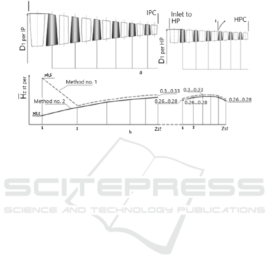
Figure 1: Flow path diagram of a twin-shaft core compressor with two ways of distributing the head coefficient values over
the stages: a - flow path diagrams for IPC and HPC; b - head coefficient distributions.
In HPC the value of 𝐻
increases from
0.26...0.28 in the first stage to 0.30...0.33 in the
middle stages and decreases to 0.26...0.28 towards the
exit from HPC.
This distribution of 𝐻
occurs because there
is an increased flow irregularity at the inlet to the first
stage and its efficiency is not high. In addition, the
choice of higher 𝐻
values in the first stages is
hindered by the desire to ensure a uniform head over
the blades' height. At the small values of the relative
hub diameter typical to the first stages, excessively
large flow turning angles can occur in the hub
sections.
In the last stages of the HPC, due to the reduced
blade height, the efficiency of the stages decreases as
a result of increased relative values of radial
clearances and an increased proportion of secondary
losses.
In addition, at the HPC outlet, in order to ensure
stable (without a stall) operation of the combustion
chamber, it is desirable that the reduced flow speed
𝜆
should not exceed 0.30...0.32. In this regard, in
the last stages of HPC the flow rate coefficient 𝐶
̅
=
𝐶
/𝑈
is sharply reduced (sometimes up to
0.39...0.41) and the Stepanov load coefficient 𝐻
/𝐶
̅
increases (Stepanov, G.Yu., 1958). In order to keep
the latter from exceeding the limit value of 0.65, it is
necessary to reduce the head at the last stages.
Reducing the head in the first and last stages of
the compressor cascade also has a beneficial effect on
providing the required gas-dynamic stability margin
of the MAC in off-design modes.
At the second method of coefficient values
distribution of consumed head by stages at the first
stage of IPC it is proposed by Gelmedov, F.S. (2003),
Matveev V.N. (2022) to increase significantly
coefficient 𝐻
up to the value exceeding 0.50
(Fig. 1,b) by using high head (transsonic) wide-chord
stage. The nature of distribution of 𝐻
values
over the other stages of the IPC and HPC remains
practically the same. Only due to an increase in air
temperature behind the transonic stage, while
maintaining the same velocity level in relative motion
at the inlet to the 𝜆
rotor wheels, the 𝐻
values, starting from the second stage of the IPC, can
be slightly increased.
The second method of distributing 𝐻
over
the stages can in some cases reduce the number of
stages, the axial dimensions and the mass of the
MAC, but its efficiency is usually reduced.
Any distribution of 𝐻
values over the
stages must respect the equilibrium (1) and (2):
𝐿
=𝐻
𝑈
(1)
𝐿
=𝐻
𝑈
(2)
The Features of Design Calculation Stages of Parameters of Flow Path of Cascade Compressor of Twin Shaft Gas Turbine Engine Core on
Base of 1D and 2D Dimensional Models of Their Working Process
227

where 𝑈
and 𝑈
are circumferential
speeds on the periphery of i-th rotor wheels of the IPC
and HPC.
2. The initial distribution of the efficiency values
for the IPC and HPC stages is based on the
considerations outlined in point 1.
At the middle and last stages of the IPC, as well
as at the middle stages of the HPC, the highest stage
efficiencies are assigned from the range 𝜂
=
0.900...0.910. For the first subsonic and transonic
stage, the efficiency value decreases in comparison
with 𝜂
by 1.5...2.0 %, for the second stage
by 0.7...1.0 %, and for the third stage by 0.3...0.5 %.
If the first stage is supersonic, its efficiency value
decreases by 3.0...4.0% relative to 𝜂
.
At the penultimate stage of HPC value of
efficiency decreases by 0.3...0.5 % in comparison
with 𝜂
, and at the last stage - by 0.7...1.2 %.
Thus, each i-th stage of IPC and HPC is assigned
in the first approximation to the efficiency value
𝜂
.
3. Stage-by-stage thermodynamic calculation of
each compressor cascade, from the first stage to the
last stage, is carried out in the usual way, for example,
as proposed by Belousov A.N. (2006) using 𝜋−𝑖−
𝑇 -functions (Dorofeev, V.M., 1973) to take into
account the change in the specific heat capacity of air
as its temperature changes.
Usually, this calculation of the IPC and HPC is
carried out in several iterations in order to clarify the
pressure ratio and the efficiency of each stage of the
MAC.
4. In case of air intake behind e.g. I-stage of HPC
(Fig. 1,a) for turbine cooling, the cascade efficiency
value is found by the formula (3):
𝜂
=
𝐺
(
𝑖
∗
−𝑖
∗
)
+𝐺
(𝑖
∗
−𝑖
∗
)
𝐺
(
𝑖
∗
−𝑖
∗
)
+𝐺
(𝑖
∗
−𝑖
∗
)
(3)
where
𝐺
is the air flow rate from the inlet of the
HPC to the outlet of the I-stage;
𝐺
- air flow rate from the inlet of the (I+1)-
stage to the HPC outlet;
𝑖
∗
- total enthalpy of the flow at the inlet to
HPC;
𝑖
∗
and 𝑖
∗
- total enthalpies of the flow in
isoentropic and real compression process after the I-
stage of HPC;
𝑖
∗
and 𝑖
∗
- total enthalpies of the flow in
isoentropic and real compression process at the HPC
outlet.
Thus, as a result of thermodynamic calculation of
the compressor cascade, taking into account the noted
features, values of pressure ratio and efficiency of its
stages, efficiency of the whole cascade, as well as the
total pressures and temperatures of air flow in all
inter-row gaps are determined.
4 DESIGN AERODYNAMIC
CALCULATION OF THE
COMPRESSOR AT MID-
DIAMETER
The aim of the design aerodynamic calculation of the
stages of IPC and HPC core is to determine the
kinematic and thermodynamic parameters in the
characteristic sections of the flow path of the stages
at the mid-diameter (Figure 2). In this case parameters
characterizing working process of elementary blade
rows of cascades at this diameter are also determined.
The input data for the design calculations of the
MAC are energy and flow rates, thermodynamic and
aerodynamic, as well as geometric parameters, the
values of which are obtained from the previous steps
of the design calculation.
The design aerodynamic calculation of the mid-
diameter MAC stage is carried out by means of a one-
dimensional model of its working process, taking into
account the following features:
1. Based on the values of the axial velocity
components at the inlet and outlet of the MAC
𝐶
and 𝐶
, the distribution of the 𝐶
value at the inlet and outlet of each blade row of the
compressor is carried out:
in the case of IPC, it is usually assumed that
𝐶
= 𝐶
and the axial component of
the flow velocity 𝐶
along the entire
compressor flow path remains unchanged;
in case of HPC 𝐶
is smaller than 𝐶
and then two variants of 𝐶
distribution along
the compressor's flow path are possible. In the
first variant, the 𝐶
decreases from the inlet to
the outlet of the MAC from 𝐶
to the value
of 𝐶
. In the second option, the 𝐶
value in the first few stages remains unchanged
and equal to 𝐶
, and in the subsequent stages
𝐶
gradually decreases from the value of
𝐶
to the value of 𝐶
. At the same
time the decrease of 𝐶
in one blade row
should not exceed 10...12 m/s (Belousov A.N.,
2006).
SIMULTECH 2023 - 13th International Conference on Simulation and Modeling Methodologies, Technologies and Applications
228
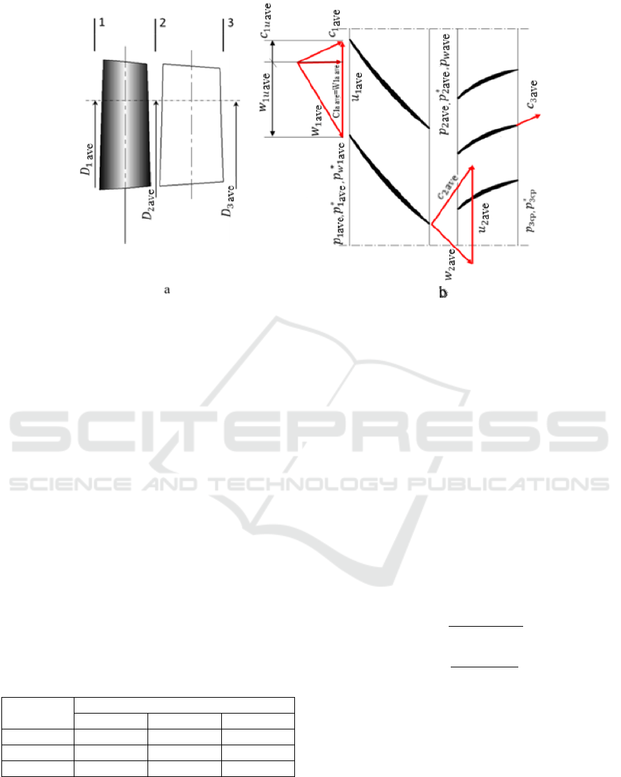
Figure 2: Compressor stage scheme: a - in the meridional plane; b - in the circumferential plane.
Further, during aerodynamic calculation in
different cross-sections along the blade height the
distribution of 𝐶
along the blade rows can be
changed and specified, in particular in order to
provide acceptable values of flow angles in relative
motion 𝛽
, flow turning angles ∆𝛽
and reduced flow
speed in relative motion at the inlet to the rotor wheels
(RW).
2. Initial distribution of 𝜌
degree of
reactivity by MAC stages is made taking into account
the recommendations of Table 1 (Belousov A.N.,
2006).
At the subsequent steps of aerodynamic
calculation distribution of 𝜌
values by stages is
specified in accordance with rational values of static
pressure ratio in RW grids 𝐶
=(𝑝
−𝑝
)/
(𝑝
∗
−𝑝
) and guide vanes (GV) 𝐶
=(𝑝
−
𝑝
)/(𝑝
∗
−𝑝
) at different radii of FP (Koch, C.C.,
1981).
Table 1: Range of 𝜌
values depending on the type and
position of stage in the MAC.
Stage type Position of stage in the MAC
first middle last
Subsonic 0.50….70 0.50…0.70 0.65…0.80
Transonic 0.65…0.75 - -
Supersonic 0.70…0.80 - -
After that, aerodynamic calculation of stages of
IPC and HPC at the middle diameter is carried out in
the traditional sequence, presented, in particular, by
Belousov A.N. (2006).
In order to obtain an efficient and stable
compressor, attention must be paid to the values of
the following relative parameters that characterise its
operation.
1. Flow braking in relative motion in RW 𝑊
/
=
𝑊
/𝑊
and in absolute motion in GV 𝐶
/
=
𝐶
/𝐶
(De Heller criterion). In order to avoid
increased hydraulic losses in the RW and GV, the
values of these ratios must be greater than 0.70
(Kampsti, N., 2000). Otherwise, it will be necessary
to change the 𝜌
value. If the required 𝑊
/
or
𝐶
/
cannot be achieved in this way, it will be
necessary to reduce the required head and redistribute
the 𝐻
values across the MAC stages.
2. Formulas (4) and (5) for static pressure ratio in
RW and GV:
𝐶
=
𝑝
−𝑝
𝑝
∗
−𝑝
(4)
𝐶
=
𝑝
−𝑝
𝑝
∗
−𝑝
(5)
In order to avoid increased hydraulic losses in the
RW and GV, these coefficients must not exceed 0.40
(Koch, C.C., 1981). The values of
𝐶
and
𝐶
can be influenced by changing the degree of
reactivity 𝜌
. In subsonic compressor stages it is
advisable to ensure an approximate equality of
𝐶
and 𝐶
coefficients.
3. Theoretical head coefficient 𝐻
=𝐻
/
𝑈
calculated from the peripheral circumferential
speed of the RW 𝜂𝐷
𝑛/60.
The Features of Design Calculation Stages of Parameters of Flow Path of Cascade Compressor of Twin Shaft Gas Turbine Engine Core on
Base of 1D and 2D Dimensional Models of Their Working Process
229

The value of this coefficient must not exceed 0.33
(Kholshevnikov K.V., 1970, Belousov A.N., 2006).
Otherwise, it is necessary to reduce the consumed
head of the stage or to increase, if it is possible under
the condition of limiting the value of reduced relative
flow velocity in relative motion at the RW inlet
𝜆
, circumferential velocity 𝑈
.
4. Flow rate coefficient calculated from the
peripheral circumferential velocity of the RW 𝐶
̅
=
𝐶
/𝑈
.
Statistics show that at the inlet to the first stage of
the IPC the 𝐶
̅
value is usually in the range of
0.45...0.55, and at the inlet to the first stage of the
HPC it is in the range of 0.45...0.50. At the IPC outlet,
𝐶
̅
= 0.45...0.55, and at the HPC outlet, 𝐶
̅
=
0.40...0.45 (Kholshevnikov K.V., 1970).
5. Stepanov load coefficient 𝐻
=𝐻
/𝐶
̅
.
In order to ensure the highest stage efficiency, it
is advisable that the value of this coefficient does not
exceed 0.65. Rational range of Stepanov load
coefficient values is 0.55...0.65 (Stepanov, G.Yu.,
1958).
5 DESIGN AERODYNAMIC
CALCULATION OF THE
COMPRESSOR ALONG THE
RADIUS OF THE FLOW PATH
The purpose of the design aerodynamic calculation of
MAC stages along the radius is to determine
kinematic and thermodynamic parameters in
characteristic sections of the stage flow path at
different radii - from the hub to the peripheral one.
Besides, at the same radii it is reasonable to find
values of parameters characterizing working process
of elementary blade rows and stages as a whole, such
as static pressure ratio coefficients, flow braking in
RW and GV, coefficients of theoretical head and flow
rate, calculated by circumferential speed at RW
periphery, Stepanov load coefficients.
As input data for the calculation geometrical
parameters of the flow path in the meridional plane,
parametric diagrams (total pressure and temperature
as well as flow angle) along the radius at the IGV inlet
and values of flow parameters at average diameters of
the MAC stages are used.
Design aerodynamic calculation of the MAC
stage at different radii is carried out in the traditional
way using two-dimensional axisymmetric model of
the working process and is accompanied by the
following features.
1. When determining the distribution of static
pressure, static temperature and flow density at the
inlet to the IGV of IPC it is necessary to take into
account the unevenness of the total pressure and total
temperature and flow angles in this section, for which
the equation of radial equilibrium with the curvature
of the current lines in the meridional plane is used.
This problem is solved discretely on
axisymmetric circles, by which the whole cross-
section plane at the IGV inlet is divided into m (m ≥
16...20) ring sections of equal area, located from hub
diameter to middle diameter, and the same number of
ring sections of equal area, located from middle
diameter to peripheral diameter (Figure 3).
The calculation circles at the RW inlet and outlet
sections, as well as at the GV outlet of each stage of
the IPC and HPC, are then formed in a similar way.
It should be noted here that, due to the presence of
boundary layer on the hub and peripheral FP surfaces,
the axisymmetric model does not allow obtaining
reliable calculation results in this area. Therefore, it is
reasonable to determine the values of flow parameters
in the 2D model at the circumferences corresponding
to the hub and periphery by extrapolating the values
of the related parameters at the preceding
circumferential cross-sections.
2. The flow swirl law at the RW inlet 𝐶
=
𝑓(𝐶
;𝑟
) can be set not only analytically, but
also with corrections to the selected 𝐶
=
𝑓
(
𝐶
;𝑟
)
+∆𝐶
pattern.
3. Pressure ratio of the stage 𝜋
∗
can be set not
only constant, but also variable along the radius,
taking into account its value at the average diameter
𝜋
∗
=𝑓
(
𝜋
∗
;𝑟
)
.
4. Distribution of values of relative efficiency of
the stage 𝜂̅
=𝜂
/𝜂
(j - number of the
calculation circle) over the height of the flow path is
carried out as follows. At value of relative hub
diameter 𝑑
̅
=𝐷
/𝐷
=𝑟
/𝑟
of the stage
in the range 0.65...0.92, typical for HPC (Belousov
A.N., 2006), in the first approximation over all height
of the blade is taken 𝜂̅
=1.
In a range 𝑑
̅
= 0.45...0.65, typical for IPC
(Belousov A.N., 2006), in area of 10 % of blade
height in hub and peripheral zones it is reasonable to
reduce relative efficiency 𝜂̅
linearly to tract
surfaces by ∆𝜂̅
= 0.03...0.05. In this case in a range
of change of relative blade height ℎ
=ℎ
/ℎ =
(𝑟
/𝑟
−𝑑
̅
)/(1 − 𝑑
̅
) from 0 to 0.1
dependence 𝜂̅
=1+∆𝜂̅
(10ℎ
−1) should be
used, and in a range ℎ
= 0.9...1.0 - 𝜂̅
=1+
∆𝜂̅
(9 − 10ℎ
).
SIMULTECH 2023 - 13th International Conference on Simulation and Modeling Methodologies, Technologies and Applications
230
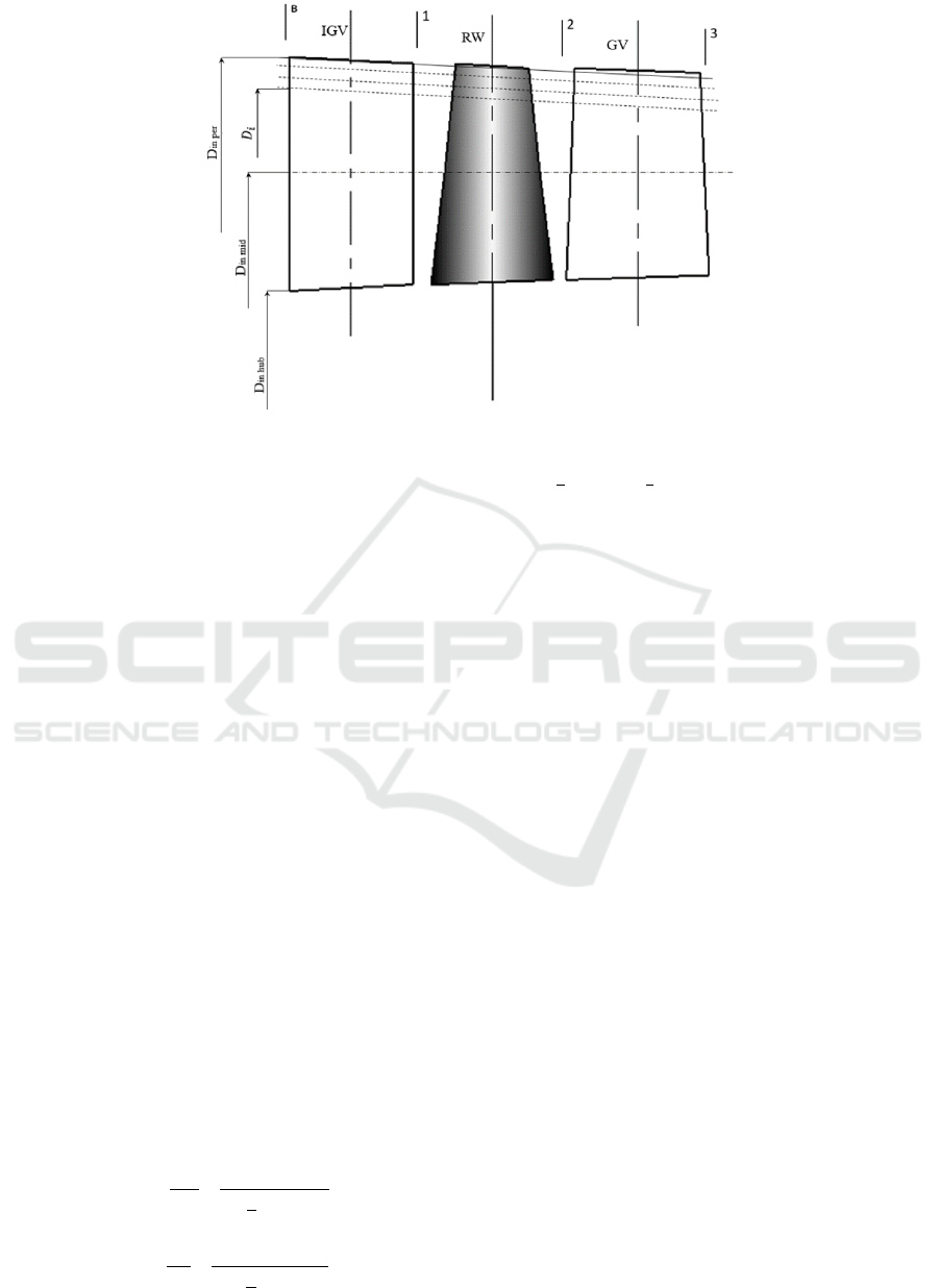
Figure 3: Two-dimensional axisymmetric flow scheme in the first compressor stage.
5. Values of axial component of flow velocity on
design circles in interventional gaps are determined
by means of connection equation of circumferential
and axial components of flow velocity without taking
into account curvature of current lines in meridional
plane, but taking into account dependences 𝐶
=
𝑓
(
𝐶
;𝑟
)
±∆𝐶
and 𝜋
∗
=𝑓
(
𝜋
∗
;𝑟
)
.
6 AN ASSESSMENT OF THE
GEOMETRIC VALUES OF THE
PROFILES AND THEIR GRIDS
AT VARIOUS CROSS-
SECTIONS ALONG THE
HEIGHT OF THE
COMPRESSOR FLOW PATH
Preliminary estimation of geometric profile values
from the results of aerodynamic calculation of
compressor stages along the radius is carried out
using traditional methods, for example, the method
presented by Belousov A.N. (2006), Bykov. N.N.
(1984). Additionally, it is advisable to determine the
values of diffusivity factor by S. Liebling’s of RW
and GV grids at all design j-th radii at the end of the
calculation:
𝐹
=1−
𝑊
𝑊
+
(𝑊
−𝑊
)
2(
𝑏
𝑡
)
𝑊
(6)
𝐹
=1−
𝐶
𝐶
+
(𝑊𝐶
−𝐶
)
2(
𝑏
𝑡
)
𝐶
(7)
where
(
)
and (
)
are the solidity of the RW and
GV grids at the calculated j-th radii.
It is considered rational to provide values of S.
Liebling’s diffusivity factor in the range of 0.40...0.50
(Kampsti, N., 2000). An acceptable value of this
parameter in the process of calculation is most often
achieved by changing the density of the grid profiles.
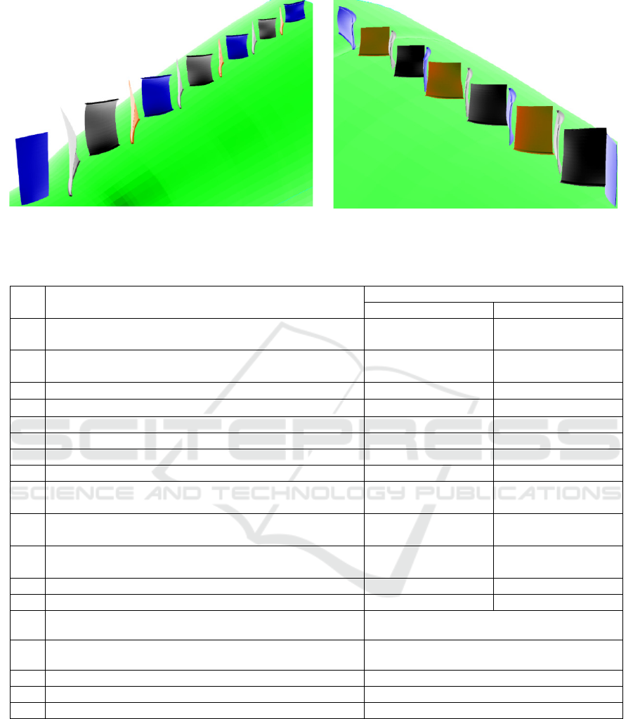
Initial three-dimensional models of IPC and HPC
(Figure 4) of perspective core have been created
taking into account the above features of steps of
design calculation of parameters of flow path
cascades of compressor of two-shaft CORE. The
schematic of these compressors in the meridional
plane with observance of proportions in axial and
radial directions has been presented earlier in Fig. 1,a.
7 CONCLUSIONS
In the article the revealed features of design
calculation of FP parameters of cascade compressor
of two-shaft core are resulted, which have allowed to
supplement a matrix of requirements to one-
dimensional and two-dimensional models of working
process of multistage compressors with specific
requirements to similar models of IPC and HPC,
which are summarized in Table 2. In the same table,
the requirements for the relative MAC parameters
characterising the working process of stages and their
blade rows, which are quite often discussed in
textbooks and articles on compressor theory, but
rarely used in published methods for their design
calculations, are also presented.
The Features of Design Calculation Stages of Parameters of Flow Path of Cascade Compressor of Twin Shaft Gas Turbine Engine Core on
Base of 1D and 2D Dimensional Models of Their Working Process
231
Intermediate pressure compresso
r
. High pressure compresso
r
.
Figure 4: Three-dimensional models of IPC and HPC.
Table 2: Additional requirements for one- and two-dimensional IPC and HPC working process models.
No Parameter
Required range of values or pattern
IPC HPC
1
Coefficient of consumed head of the first subsonic stages
𝐻
0.20…0.26 0.26…0.28
2
Coefficient of consumed head of the first transonic or
supersonic stages 𝐻
0.50…0.60 -
3
Coefficient of consumed head of the middle stages 𝐻
- 0.30…0.33
4
Coefficient of consumed head of the last stages 𝐻
0.30…0.33 0.26…0.28
5
Efficiency of the first subsonic or transonic stages
0.885…0.895 0.880…0.890
6
Efficiency of the first supersonic stage
0.865…0.880 -
7
Efficiency of the middle stages
0.905…0.910 0.900…0.905
8
Efficiency of the last stages
0.880…0.890 0.875…0.885
9
Regularity of the relative efficiency of the stage over the
blade height at ℎ
=0.1
𝜂
̅
=1+∆𝜂
̅
(10ℎ
−1) 𝜂
̅
=1
10
Regularity of the relative efficiency of the stage over the
blade height at ℎ
=0.1…0.9
𝜂
̅
=1 𝜂
̅
=1
11
Regularity of the relative efficiency of the stage over the
blade height at ℎ
=0.9…0.10
𝜂
̅
=1+∆𝜂
̅
(9 − 10ℎ
) 𝜂
̅
=1
12
Flow rate coefficient of the first stages
0.45…0.55 0.45…0.50
13
Flow rate coefficient of the last stages
0.45…0.50 0.40…0.45
14
Allowable reduction in the axial component of the flow
velocit
y
in one blade row
10…12 m/s
15
Flow braking in RW in relative motion and in GV in absolute
motion
≥
0.7
16
Static pressure ratio in the RW and GV
≤
0.4
17
Stepanov load factor
0.55…0.65
18
S. Liebling's diffusivity factor of the RW and GV grids
0.40…0.50
ACKNOWLEDGEMENTS
The research was supported by Russian Science
Foundation grant no. 22-79-00210.
REFERENCES
Kholshevnikov K. V. (1970). The book, Theory and
Calculation of Aircraft Blade Machines. Moscow,
Mashinostroenie.
Belousov A. N. (2006). The book, Design
thermogasodynamic calculation of the main parameters
SIMULTECH 2023 - 13th International Conference on Simulation and Modeling Methodologies, Technologies and Applications
232

of aviation blade machines. Samara: Publishing house
of Samara State Aerospace University.
Hirsch, C. (2007). The book, Elsevier.
Bykov, N. N. (1984). The book, Choice of parameters and
determination of the main dimensions of compressors
and gas turbines of gas turbine generators of GTE.
Moscow: MAI Publishing House.
Gelmedov, F. S. (2002). The book, Methodology of axial
compressor design. Teploenergetika.
Belousov A. N. (2003). The book, Theory and Calculation
of Aircraft Blade Machines. Samara: Publishing house
"Samara House of Printing".
Matveev V. N. (2022). The book, Algorithm of forming the
appearance of the flow part of the blade machines of the
twin-shaft gas generator of an aviation gas turbine.
Vestnik RGATU.
Stepanov, G. Yu. (1958). The book, Fundamentals of Blade
Machines Theory, Combined and Gas Turbine.
Dorofeev, V. M. (1973). The book, Thermogasdynamic
calculation of gas-turbine power plants (in Russian).
M.: "Machine engineering".
Koch, C. C. (1981). The book, Stalling Pressure Rise
Capability of Axial Flow Compressor Stages. J. Eng.
Eng. Power.
Kampsti, N. (2000). The book, Aerodynamics of
compressors. M.: Mir.
The Features of Design Calculation Stages of Parameters of Flow Path of Cascade Compressor of Twin Shaft Gas Turbine Engine Core on
Base of 1D and 2D Dimensional Models of Their Working Process
233
