
Improving the Thermal Condition of the High-Pressure Turbine
Blade
V. M. Zubanov
a
, G. M. Popov
b
, S. A. Melnikov
c
, A. I. Sherban
d
and Liu Xin
e
Department of Aircraft Engine Theory, Samara National Research University,
34 Moskovskoe Highway, Samara, Russian Federation
Keywords: Aircraft Engine, Turbine Cooling, Cooled Blades, Cooling Efficiency Coefficient.
Abstract: An increase in the temperature of the gases forces the cooling system of the turbine blades to become more
and more complex. The presented article describes a complex and computer-intensive numerical model of a
working blade of a modern high-pressure turbine of a civil aviation aircraft gas turbine engine, which includes
a flow region, a blade body, internal cooling channels and coolant supply channels. Using this model, the
thermal state of the blade was determined and potential problem areas were found: hot gas leakage, coolant
stagnation and overheating. Based on the analysis, several options were proposed for changing the
configuration of the internal channels of the blade, which reduce the negative effects found. Although the
proposed design options did not fully achieve all the requirements for the blade, they made it possible to find
promising ways for further improvement. Also, the authors have practically worked out conjugate numerical
models to study the thermal state of the turbine.
1 INTRODUCTION
The operation of modern gas turbine engines (GTE)
is impossible without a cooling system for high-
temperature gas turbine components. Therefore, the
turbine cooling system includes cooling of the nozzle
blades (NB) and rotor wheels (RW). The cooling
schemes for the NB and RW in the first stage of a
high-pressure turbine (HPT) are the most complex.
They must ensure a component temperature at which
the turbine can operate effectively throughout its full
service life, bearing in mind that the total working
fluid temperature at the combustion chamber outlet
𝑇
∗
can exceed 1800 K in modern engines (Han
J.C.,2012, Inozemtsev A.A., 2006).
Different schemes of cooling air channels, which
contain heat exchange intensifiers, are used to cool
the HPT rotor blades (Kopelev S.Z., 1983, Nagoga
G.P.,1996, Vieser, W., 2002). The design of effective
blade cooling schemes is a time-consuming process,
a
https://orcid.org/0000-0003-0737-3048
b
https://orcid.org/0000-0003-4491-1845
c
https://orcid.org/0000-0002-0170-3846
d
https://orcid.org/0000-0001-6699-3541
e
https://orcid.org/0000-0002-3137-8247
which is currently difficult to imagine without the use
of CFD tools.
The purpose of this work was to perform a
detailed analysis of the thermal condition of the
cooled HPT rotor blade (RB) using the Ansys CFD
Post software, and to develop and implement
measures to improve the thermal condition of the
blade and increase the efficiency of its cooling
scheme.
In the course of this work, alternative schemes of
internal cooling channels were developed based on
the analysis of the thermal condition of the HPT rotor
blades. Geometric models of the blade under study
were created with preservation of the external shape
and different schemes of internal cooling channels.
Using these models, several series of calculations
were carried out. The results of various cooling
schemes have been compared with each other in order
to assess the effect of changes in the HPT rotor blades
cooling scheme on its temperature condition.
234
Zubanov, V., Popov, G., Melnikov, S., Sherban, A. and Xin, L.
Improving the Thermal Condition of the High-Pressure Turbine Blade.
DOI: 10.5220/0012078400003546
In Proceedings of the 13th International Conference on Simulation and Modeling Methodologies, Technologies and Applications (SIMULTECH 2023), pages 234-242
ISBN: 978-989-758-668-2; ISSN: 2184-2841
Copyright
c
2023 by SCITEPRESS – Science and Technology Publications, Lda. Under CC license (CC BY-NC-ND 4.0)
2 COMPUTATIONAL MODEL
PREPARATION
As the initial data, the results of calculation of the
thermal condition of the initial variant of the HPT RB
cooling scheme were used. This cooling scheme is
referred to hereinafter as the "basic" one, since
modified cooling channels schemes were created
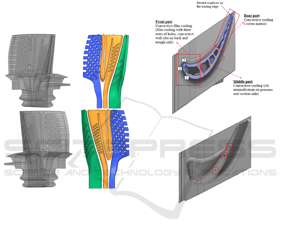
based on it. The geometric model of the "basic" blade
and its inner cavity is shown in Figure 1.
Figure 1: Shape of the basic rotor blade and its inner cavity.
Three-dimensional geometric models of the blade
and gas-air regions were created in the Siemens NX
software package. The RB inner cavity had a complex
system of channels and included different types of
convective cooling intensifiers, shown in Figure 2.
The blade has a total of three internal channels:
front, middle and rear. The rear part of the blade is
cooled by means of a vortex cooling matrix formed
by crossed ribs which are moulded on the inner
surfaces of the pressure and suction side. The coolant
exits from the vortex matrix into the flow path
through 8 slotted windows near the trailing edge. In
the front and middle inner channels there are ribs on
the pressure and suction side walls to intensify
convective cooling. The upper part of the vortex
matrix is fed with coolant by means of additional
openings from the middle channel. There are three
vertical rows of holes near the leading edge of the
blade to form a film cooling on the surface of the
blade. The first row has 16 holes, the second and third
rows have 17 holes each. All holes have a diameter of
0.55mm. The film cooling of the upper blade face is
formed by blowing out a part of the coolant through
four holes of 1 mm diameter on the peripheral end of
the HPT RB.
Figure 2: Blade cooling scheme, top view.
The computational model for the coupled
thermal-hydraulic calculation of the RB was created
in Ansys CFX (Ansys Workbench Product Release
Notes). The CFD model of the RB consisted of four
domains (Figure 3):
the stationary domain of the NB blade passage
channel;
the rotating domain of the RW blade passage
channel, also including the inter-disk cavity in
front of and after the RW;
rotating domain of the front, middle and rear parts
of the inner cavity of the RW;
the rotating domain of the cooling air inlet to the
blade.
Inlet 1 is the cross-section at the main flow inlet
to the HPT;
Improving the Thermal Condition of the High-Pressure Turbine Blade
235

Inlet 2 - cross-section at the inlet to the RB cooling
system;
Inlet 3 - cross-section at the inlet to the cooling
area of the front surface of the RW disc;
Inlet 4 - cross-section at the inlet to the cooling
area of the rear surface of the RW disc;
Outlet - cross-section at the outlet of the main
flow from the HPT.
Figure 3: Computational model for coupled thermal-
hydraulic calculation of the rotor blade.
The numerical values of the initial data were taken
according to the results of the thermodynamic and
hydraulic calculation of the engine, as well as the 1D
calculation of the turbine.
The calculation took into account the fact that in
the model there are 2 working bodies (air and
combustion products), while taking into account that
they depend on the gas temperature (Dorofeev V.M.,
1973).
3 ANALYSIS OF BASIC ROTOR
BLADE COOLING SCHEME
Figures 4 and 5 show calculated temperature
distributions on external and internal surfaces of the
rotor blade at cooling air flow rate 𝐺
= 4.2% of gas
flow rate through throat of inter-blade channels of NB
𝐺
.
.
The maximum value of the calculated RB
temperature occurs in the periphery area closer to the
trailing edge and is 1136.8 °C.
Figure 6 shows the distribution of temperature
values and their average value in cross-sections
located at different heights of the RB.
The maximum value of the calculated RB
temperature occurs in the periphery area closer to the
trailing edge and is 1136.8 °C./
Figure 4: Temperature distribution on the external surfaces of
the rotor blade.
Figure 5: Temperature distribution on the internal surfaces of
the rotor blade.
Figure 6: Shape of the basic rotor blade and its inner cavity.
Figure 6 shows the distribution of temperature
values and their average value in cross-sections
located at different heights of the RB.
SIMULTECH 2023 - 13th International Conference on Simulation and Modeling Methodologies, Technologies and Applications
236

Based on the obtained cross-sectional temperature
distribution, the following problem areas were
identified for the studied RB.
Firstly, it is the overheated peripheral part of the
blade at the exit edge. And, secondly, there is an area
with temperature difference more than 150°С from
the middle of internal rib to the external surface of the
suction side at the blade bottom (see Fig. 6, section at
relative height from the hub equal to 5%). The
presence of this zone leads to stresses that reduce the
low-cycle fatigue margin.
Increased irregularity of the temperature field in
the blade is caused by vortex zones and stagnation
zones in the cooling channels. Examples are shown in
Figures 7 and 8.
On the basis of the problems described, proposals
have been developed for refining the internal cooling
channels of the RB.
Figure 7: Vortex flow zone in the film cooling channel.
In order to eliminate the vortex in the film cooling
channel, the shape of the channel was corrected,
namely the ratio of the maximum cross-sectional area
of the channel to the inlet cross-sectional area was
reduced by a factor of 1.3. The cross-sectional areas
of the film cooling channel have been modified as
shown in Figures 9 and 10.
To reduce the blade temperature near the trailing
edge, the shape of the internal channels was changed,
through which air entered the matrix and was then
discharged into the flow path of the turbine through
the holes in the trailing edge. This also reduced
hydraulic losses in the new channel configuration.
Figure 8: Stagnation zone in the film cooling channel.
Figure 9: Cross-sectional areas of the film cooling channel
of the basic scheme.
Connecting the film cooling channel to the vortex
matrix channel helped to get rid of the stagnation zone
and to additionally supply the overheated area around
the trailing edge at the blade periphery with cooling
air.
Improving the Thermal Condition of the High-Pressure Turbine Blade
237
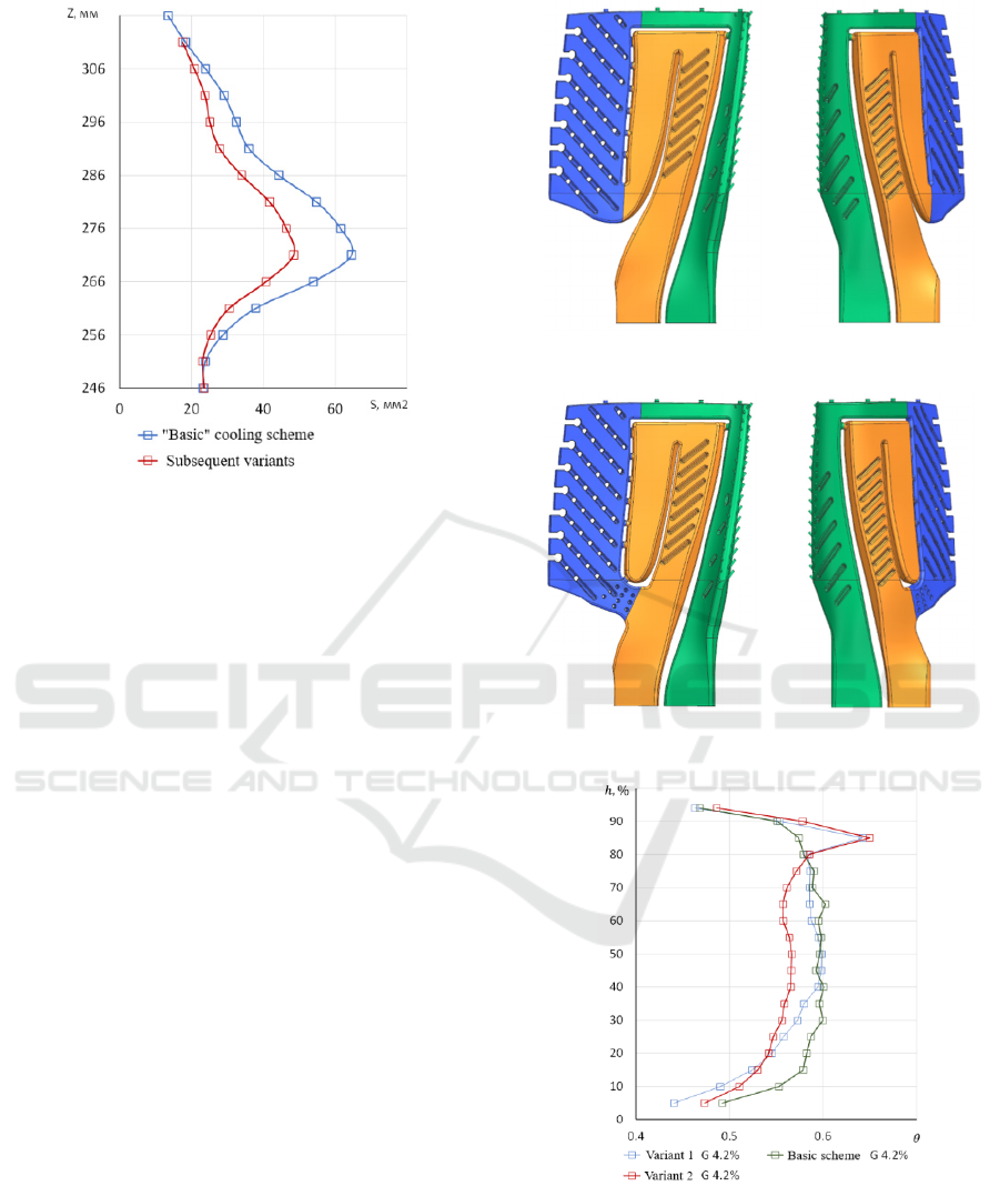
Figure 10: Change in cross-sectional area of the film
cooling channel.
However, the film cooling operation was more
difficult to regulate with this arrangement, because
once all the channels were connected, the other two
channels began to influence the film cooling
parameters.
Also, to eliminate overheating near the trailing
edge, the number of holes connecting the middle
channel and the vortex matrix cavity was changed.
Instead of five holes, unevenly spaced across the
blade height, six holes were made without taking into
account the overflow between the film cooling
channel and the vortex matrix channel. In the new
schemes, the holes were positioned directly opposite
the openings in the trailing edge.
4 ANALYSIS OF NEW ROTOR
BLADE COOLING SCHEMES
Figures 11 and 12 show the new cooling scheme
variants, labelled "Variant 1" and "Variant 2".
For the "Variant 1" and "Variant 2" cooling
schemes, calculations are performed at the same
boundary conditions as for the blade with the basic
internal cooling channel scheme.
Figures 13 and 14 shows distribution of cooling
efficiency coefficient θ over blade height of all three
schemes at cooling air flow rate 𝐺
= 4.2% of
𝐺
.
.
Figure 11: Cooling scheme "Variant 1".
Figure 12: Cooling scheme "Variant 2".
Figure 13: Comparison of cooling efficiency with
different channel schemes.
SIMULTECH 2023 - 13th International Conference on Simulation and Modeling Methodologies, Technologies and Applications
238
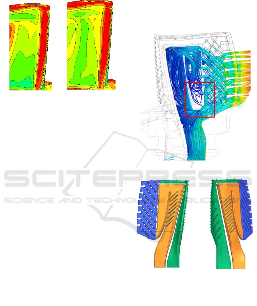
Figure 14: Temperature at leading edge of blades with hot
air intake for "Variant 1" and "Variant 2" schemes.
Variant 1 performed better than the Variant 2. In
Variant 2, due to the geometry of the channels, large
vortex and stagnation zones were created, which were
not supplied with cooling air. The vortex inside the
cooling channels can be clearly seen in Figure 15. The
part of the channel that was not receiving cooling air
is also marked here. Therefore, for the subsequent
improvement of the cooling channel system, the
"Variant 1" scheme was selected.
The cross-sectional area of the channel connecting
the film cooling cavity and the vortex matrix was
halved to eliminate hot gas flowing into the blade's
inner cavity in order to increase the static pressure in
the film cooling cavity. The modified "Variant 1.2"
cooling channel scheme is shown in Figure 16.
As can be seen from Figure 20, it was possible to
significantly reduce the trailing edge temperature as a
result of redistributing the cooling air flow in the
vortex matrix.
Comparison of values of average cooling
efficiency coefficient of "Variant 1" and "Variant 1.2"
schemes by sections at different radii is shown in
Figure 17, and distribution of θ by sections at
different blade heights with "Variant 1.2" scheme is
shown in Figure 18. For each blade section the
cooling efficiency coefficient 𝛩
was
determined by the formula:
𝛩
𝑇
∗
𝑇
𝑇
∗
𝑇
∗
,
where 𝑇
∗
is the total gas temperature in relative
motion in front of the rotor blade at the corresponding
radius;
𝑇
∗
- total air temperature in relative motion at
the inlet to the lower end of the rotor blade;
𝑇
- average cross-sectional
temperature of the blade.
Figure 15: Area with insufficient cooling air.
Figure 16: Cooling scheme "Variant 1.2".
As can be seen from the graphs in Figure 17,
"Variant 1" has a higher cooling efficiency than
"Variant 1.2" according to preliminary calculations.
At the same time, the cooling efficiency of the two
schemes is lower than that of the basic scheme. One
of the reasons for this is that hot gas flows into the
film cooling holes. This can be seen from the
overheated leading edge in Figure 18.
Based on the data shown in the graphs in Figure
17, it can be concluded that the "Variant 1.2" scheme
Improving the Thermal Condition of the High-Pressure Turbine Blade
239
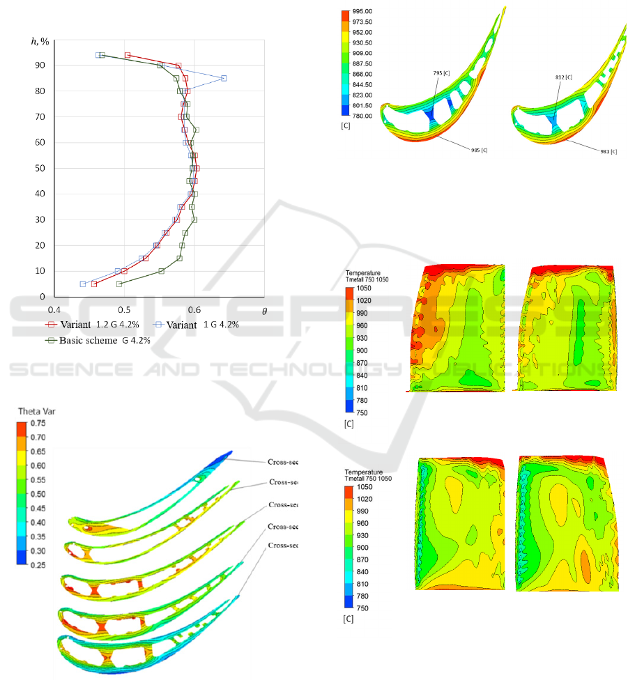
is almost identical to the base one, in terms of integral
values of section cooling efficiency at different radii.
Figure 19 shows a comparison of the blade
temperature distributions over the cross-section at 5%
of the airfoil height in the case of the base variant and
"Variant 1.2". It can be seen that in the "Variant 1.2"
scheme, the temperature gradient from the blade
internal surfaces to the external one was reduced by
changing the internal channel geometry.
Figure 17: Distribution of θ by blade height for basic
scheme and "Variant 1" and "Variant 1.2" schemes.
Figure 18: Distribution of θ across cross-sections at
different blade heights "Variant 1.2" at cooling air flow
rate 𝐺
= 4.2% of 𝐺
.
.
A comparison of the temperature distribution over
the blade surface with the basic scheme and with the
"Variant 1.2" cooling scheme is shown in Figure 20.
The "Variant 1.2" scheme has eliminated hot gas from
entering the blade cooling system through the film
cooling holes (see Figure 20, pressure side view of the
"Variant 1.2" blade).
Base scheme. "Variant 1.2" scheme.
Figure 19: Comparison of the temperature distribution
across the blade cross-section at 5% of blade height with
the basic cooling scheme and with the "Variant 1.2"
scheme.
Pressure side
view of blade with
‘basic’ cooling
scheme.
Pressure side view of
blade with ‘Variant
1.2’ cooling scheme.
Suction side view
of blade with
‘basic’ cooling
scheme.
Suction side view of
blade with ‘Variant
1.2’ cooling scheme.
Figure 20: Temperature distribution over the blade surface
with "basic" cooling scheme and "Variant 1.2" cooling
scheme.
The leading edge of the blade with cooling
scheme "Variant 1.2" is overheated in the periphery
SIMULTECH 2023 - 13th International Conference on Simulation and Modeling Methodologies, Technologies and Applications
240
area. This can be eliminated by changing the number
and geometry of the film cooling holes in the problem
area or by increasing the radius of the internal film
cooling channel at its 90⁰ turning point.
Also, as a result of changing the geometry of the
cooling channels (as evidenced by the CFD
calculation of the internal channels), an additional
positive effect was obtained by reducing the total
hydraulic resistance in the blade cavity by 116 kPa.
This means that the same cooling air flow rate can be
achieved at a lower pressure drop in the RB cooling
scheme.
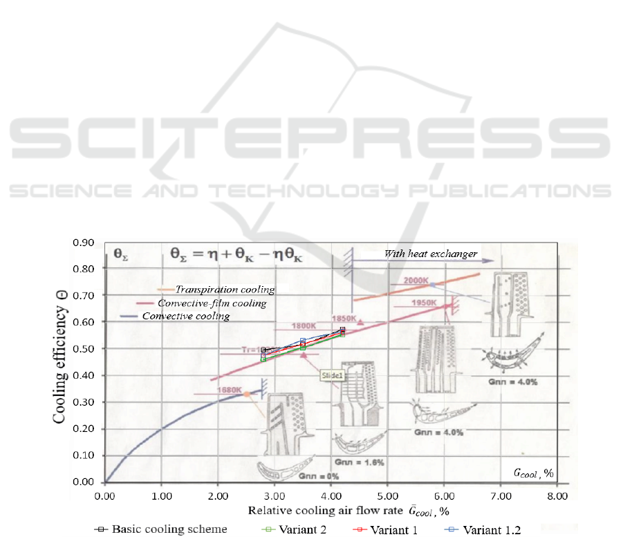
For all blade cooling schemes the values of
cooling efficiency coefficient θ at different cooling
air flow rates have been calculated. The results of
these calculations are plotted on the general graph
from study of Shevchenko M. I. (2017), see Figure
21. To be able to compare the calculated data with the
graph, the values of θ have been recalculated using
the temperature 𝑇
∗
at the inlet to the cooling
cavity in the HPT disk, and the values of relative
cooling air flow rate were recalculated depending on
air flow rate at the inlet to the high pressure
compressor of the designed engine.
5 CONCLUSIONS
The results of the analysis of the thermal-hydraulic
calculation of the basic HPT rotor blade have been
evaluated and the main directions of its refinement
have been proposed, aimed at reducing the
temperature of the trailing edge and the temperature
difference between the external and internal surfaces
of the blade.
A number of new blade cooling schemes based on
the original geometric model have been developed.
By comparing the results of conjugate modelling of
the new blades with the initial data on the basic blade,
the advantages and disadvantages of alternative
schemes of internal cooling channels of the
investigated RB were revealed.
The result is the "Variant 1.2" scheme, which
eliminated the overheating of the trailing edge and
reduced the temperature difference between the
internal and external surfaces of the blade.
Therefore, the "Variant 1.2" scheme seems to be the
most promising for further development. At the same
time, the disadvantage of this scheme is difficulty of
regulation of its operation in comparison with "basic"
scheme, because all cavities inside the blade are
connected with each other by means of special
connection channels in the scheme "Variant 1.2".
In the future, with the help of the developed
mathematical model, searches will be made for the
shape of the internal channels of the blade, which will
make it possible to obtain its best thermal state. In this
case, rational convective cooling will be found at the
first stage. Then the film cooling will be also
modified.
Figure 21: Comparison of the results of the calculation of the cooling efficiency of the rotor blades in question with the
statistical data (Shevchenko M. I., 2017).
Improving the Thermal Condition of the High-Pressure Turbine Blade
241

REFERENCES
Kopelev S. Z. (1983). The tutorial, Cooled blades of gas
turbines. Thermal calculation and profiling. Nauka
Publisher.
Nagoga G. P. (1996). The tutorial, Effective ways of
cooling blades of high-temperature gas turbines.
Moscow: MAI Publishing House.
Shevchenko M. I. (2017). Dissertation, Design of cooled
GTE parts with advanced verification of thermal-
hydraulic models by the example of cooled gas turbine
blades.
Han J. C., Dutta S., Ekkad S. (2012). The paper, Gas Tubine
Heat Transfer and Cooling Technology. Second
Edition.
Vieser, W. (2002). The paper, Heat transfer prediction
using advanced two-equation turbulence models.
Inozemtsev A. A., Sandratsky V.L. (2006). The book, Gas
Turbine Engines.
Dorofeev V. M. (1973). The book, Thermogasodynamic
Calculation of Gas Turbine Power Plants. Moscow,
Mashinostroenie.
Ansys Workbench Product Release Notes. ANSYS, Inc.
and ANSYS Europe, Ltd. are UL registered ISO
9001:2000 Companies.
SIMULTECH 2023 - 13th International Conference on Simulation and Modeling Methodologies, Technologies and Applications
242
