
Differentiated Monitor Generation for Real-Time Systems
Behnaz Rezvani
a
and Cameron Patterson
b
Bradley Dept. of Electrical and Computer Engineering
Virginia Tech, Blacksburg, VA, U.S.A.
Keywords:
Runtime Verification, Monitor, Timing Constraints, Real-Time Systems, Formal Analysis.
Abstract:
Safety-critical real-time systems require correctness to be validated beyond the design phase. In these systems,
response time is as critical as correct functionality. Runtime verification is a promising approach for validating
the correctness of system behaviors during runtime using monitors derived from formal system specifications.
However, practitioners often lack formal method backgrounds, and no standard notation exists to capture
system properties that serve their needs. To encourage the adoption of formal methods in industry, we present
GROOT, a runtime monitoring tool for real-time systems that automatically generates efficient monitors from
structured English statements. GROOT is designed with two branches, one for functional requirements and one
for specifications with metric time constraints, which use appropriate formalisms to synthesize monitors. This
paper introduces TIMESPEC, a structured English dialect for specifying timing requirements. Our tool also
automates formal analysis to certify the C monitors’ construction. We apply GROOT to timing specifications
from an industrial component and a simulated autonomous system in Simulink.
1 INTRODUCTION
Runtime verification (RV) is a dynamic verification
technique that uses monitors to observe, validate and
sometimes correct system behaviors during execu-
tion (Bartocci et al., 2018). Monitors are typically de-
rived from system requirements expressed in a formal
language such as linear temporal logic (LTL) (Pnueli,
1977). RV can be used for debugging during de-
velopment or for high-assurance applications post-
deployment. Although plenty of RV frameworks exist
that target different languages and applications (Fal-
cone et al., 2021), only a few have an explicit notion
of time and support real-time systems monitoring.
Ensuring the correct behavior of real-time systems
is challenging, as they must satisfy both functional
and non-functional requirements containing timing
constraints. However, the use of formal methods to
support these requirements is often daunting for prac-
titioners. It is a significant issue as it requires ver-
ification engineers to have a background in formal
methods and to learn the syntax of each monitoring
tool, which is often domain-specific. It is noteworthy
that timing requirements are inherently different from
functional requirements and are repetitive, allowing
a
https://orcid.org/0000-0002-1947-1764
b
https://orcid.org/0000-0003-2482-5261
the reuse of the same monitor. Accordingly, using
distinct formalisms for capturing functional and tim-
ing specifications may minimize monitors’ overhead.
To address the above issues, we propose a dual
monitoring architecture for real-time embedded sys-
tems named GROOT (Generalized Runtime mOni-
tOring Tool) that automatically generates stand-alone
non-intrusive formally verified monitors from struc-
tured English statements. Our framework uses dis-
tinct front ends, intermediate forms and formal veri-
fication techniques to translate pseudo-English func-
tional and timing specifications into monitors written
in C. To the best of our knowledge, GROOT is the first
RV tool that employs different formalisms for func-
tional and timing requirements of real-time systems.
At the front end of the functional requirement
flow, the NASA FRET tool (Giannakopoulou et al.,
2020) captures structured English properties and gen-
erates the equivalent LTL formulas. For timing con-
straints, we propose a structured English language
called TIMESPEC to express time limits, which are
then translated into timed automata (Alur and Dill,
1994). GROOT monitors are executed outside the
software/hardware system, and the application is con-
sidered a black box. The monitors are automatically
created and confirmed correct by automated formal
analysis. Processing the monitor’s inputs and manag-
Rezvani, B. and Patterson, C.
Differentiated Monitor Generation for Real-Time Systems.
DOI: 10.5220/0012080600003538
In Proceedings of the 18th International Conference on Software Technologies (ICSOFT 2023), pages 353-360
ISBN: 978-989-758-665-1; ISSN: 2184-2833
Copyright
c
2023 by SCITEPRESS – Science and Technology Publications, Lda. Under CC license (CC BY-NC-ND 4.0)
353
ing the violations are handled by separate modules to
keep the monitor structure simple.
Timing requirements are essential for both soft-
ware and hardware applications, as they refer to the
specific time intervals or deadlines that must be met
for the application to function correctly. In software,
specific tasks must be completed within a certain time
frame to ensure safety and reliability, while in hard-
ware, inputs and outputs must be precisely timed to
ensure correct operation. To demonstrate the useful-
ness of GROOT generated monitors, examples from
both software and hardware are presented.
For the sake of brevity, this paper focuses exclu-
sively on the TIMESPEC flow of GROOT, and the
main contributions are:
• TIMESPEC templates: This paper presents sev-
eral structured English statements to collect var-
ious timing bounds, providing practitioners with
a practical way to capture timing requirements
without needing a formal methods background.
• Adding metric time constraints: GROOT’s frame-
work fully automates the monitor generation pro-
cedure from TIMESPEC requirements, reducing
the need for manual intervention.
• Formally verified monitors: GROOT also pro-
vides an automated process for formally verifying
the correctness of each monitor implementation.
2 TIMESPEC OVERVIEW
To make RV more accessible to practitioners, this
paper proposes a structured English dialect called
TIMESPEC to capture timing specifications. This vo-
cabulary supports properties containing metric time
bounds by defining a set of property patterns for re-
quirements sharing similarities.
2.1 Pulse Duration
The timing of clocks and signals in digital systems
and interfaces plays a critical role in ensuring the cor-
rect behavior of the overall design. In particular, the
pulse width of certain signals must fall within a spe-
cific range to trigger the desired events. To address
this type of requirement, a pulse duration template
specifies the pulse width of a signal or period and
duty cycle of a clock signal. Table 1 shows the sup-
ported values for each field of this template. TYPE
indicates the type of pulse duration requirement. SIG-
NAL specifies the clock signal or the source of events
to be monitored. The TIMING CONSTRAINT value
depends on the specification constraint. Each time
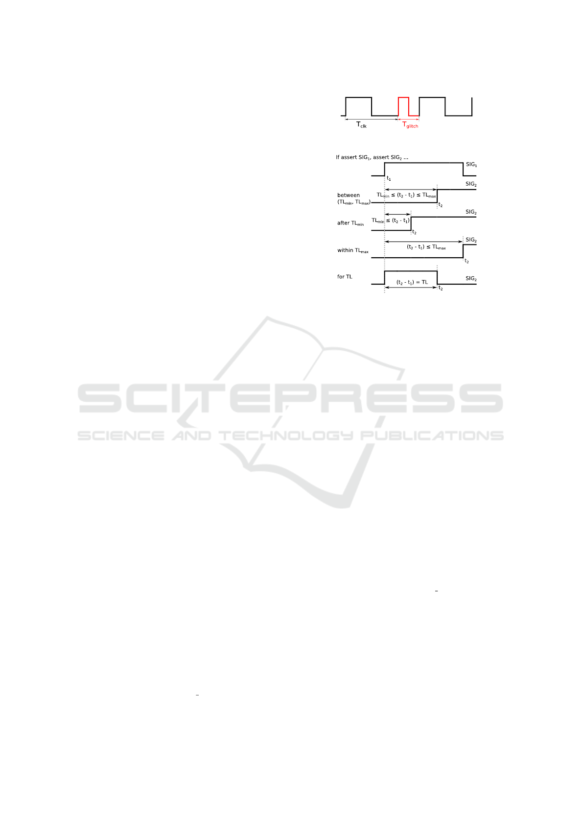
Figure 1: Clock signal including a glitch.
Figure 2: Timing diagram of TIMESPEC causality template
for specific ACTIONs and SIGNALs.
limit consists of a numeric value and its correspond-
ing time unit. The duty cycle bounds are typically
expressed as a percentage, unlike other TYPEs writ-
ten in an absolute format such as nanoseconds (ns).
Figure 1 demonstrates a clock signal (clk) with spe-
cific period (T
clk
), say 50 ms. If this clock has any
glitches to be detected, a monitor can be created by
GROOT using a TIMESPEC requirement similar to
“P1: Period of clk should be 50 ms”.
2.2 Causality
In communication protocols such as handshaking,
events often have causal relationships, where one
event may trigger another with a constraint on the
elapsed time between the two. To capture this behav-
ior, TIMESPEC uses a causality template described
in Table 2. For example, the requirement “P2: If de-
assert RESET, start CLK within 3 us” indicates the
clock signal of a digital system must start within a
specific time after the reset signal is deasserted. The
ACTION field includes asserting/deasserting signals
or starting a clock, with the SIGNAL field indicat-
ing the events involved. TIMING CONSTRAINT ex-
presses relationships between events based on time
bounds. The causality relationship can be visualized
with a timing diagram, as shown in Figure 2 to aid
practitioners in understanding this template.
3 GROOT ARCHITECTURE
Konrad and Cheng proposed a structured English
grammar to formally capture requirements (Konrad
ICSOFT 2023 - 18th International Conference on Software Technologies
354

Table 1: TIMESPEC pulse duration template.
Constraint Type Pulse Duration
Template TYPE of SIGNAL should be TIMING CONSTRAINT.
TYPE active pulse width, period, duty cycle
SIGNAL Source of events such as: CLK, RESET
TIMING CONSTRAINT TL, >= TL
min
and <= TL
max
, >= TL
min
, <= TL
max
Time limits (value + time unit) TL
min
(lower bound), TL
max
(upper bound), TL (duration)
Time unit %, ns, us, ms, s, min, h
Table 2: TIMESPEC causality template.
Constraint Type Causality
Template If ACTION SIGNAL, ACTION SIGNAL TIMING CONSTRAINT.
ACTION assert, deassert, start
SIGNAL Source of events such as: CLK, START
TIMING CONSTRAINT between TL
min
and TL
max
, after TL
min
, within TL
max
, for TL
Time limits (value + time unit) TL
min
(lower bound), TL
max
(upper bound), TL (duration)
Time unit ns, us, ms, s, min, h
and Cheng, 2005). However, temporal logics are
declarative while monitors require an operational de-
scription such as automata to be implemented effec-
tively. An overview of timed automaton (TA) will be
given next, followed by GROOT’s monitor automata
and its synthesis procedure.
3.1 Timed Automaton
A TA is a finite automaton equipped with a finite set
of real-valued clocks for modeling timed behaviors
of real-time systems (Alur and Dill, 1994). TA can
be considered as a directed graph, where the nodes
and edges are the states and transitions, respectively.
Clock constraints guard states and transitions to re-
strict the behavior of the automaton.
The semantics of TA is a timed transition system
that specifies how the automaton behaves over time
in response to events and clock constraints. Figure 3
represents a TA for requirement P2 from Section 2.2.
The state q
0
is the initial state while q
0
and q
2
are
the accepting states (denoted as double green circles).
The events include “e
0
(e
2
): deasserting (asserting)
RESET” and “e
1
: starting CLK”. This TA has one
clock x, and the guard x ≤ 3 is assigned to the non-
accepting state q
1
to limit its duration in q
1
. The TA’s
clock is assumed to be increased with a pace of 1 us.
When RESET is deasserted, the TA resets the
clock (x := 0) and moves to q
1
, where it can stay for
!RESET, x := 0
q
1
q
0
RESET
q
3
CLK, x ≤ 3, x := 0
x > 3
RESET, x := 0
q
2
x ≤ 3
Figure 3: Property “P2: If deassert RESET, start CLK within
3 us” illustrated by a TA.
a maximum of 3 units. If e
1
does not occur before
passing 3 units, the TA moves to the non-accepting
state q
3
(marked as a red circle), which indicates a vi-
olated behavior. If e
1
does occur within 3 units, the
TA moves to q
2
and the clock is reset. The accepting
state q
2
has no constraint, which allows the TA to re-
main in this state until e
2
occurs. This TA is determin-
istic as there is, at most, one transition for any given
state and set of clock values. This example demon-
strates that a TA is a straightforward and expressive
structure for capturing the timing aspects of a system.
3.2 Monitor Structure
It is paramount to approach the addition of monitors
carefully to avoid compromising system performance.
To minimize overhead and ensure isolation, GROOT
monitors are performed outside the system and the
application is treated as a black box. The monitors
are kept simple by using separate external modules to
translate inputs into relevant Boolean atomic proposi-
tions (APs) and handle any necessary actions in case
of violation. This simplicity makes the monitor au-
tomata suitable for automated formal analysis.
Figure 4 depicts the monitor code structure. The
block Main and its components are automatically gen-
erated by GROOT and will be explained later. It is as-
SUS
Monitor
Inform the user in case of violation
Main
Input_Handler
Monitor_Inputs
{
EVE1
EVE2
EVE3
Monitor_State
{
state
error
state_duration
Monitor_State.error
Error_Handler
0
1
.
Figure 4: Monitoring process structure.
Differentiated Monitor Generation for Real-Time Systems
355

sumed that Main and the system under scrutiny (SUS)
share the same time reference and Monitor is called
periodically based on the SUS time signals. If the
inputs have a different time base, a separate clock sig-
nal can be used for Main to invoke Monitor whenever
new data are available. The Input Handler module
processes the inputs and extracts the necessary infor-
mation from SUS signals to create events (i.e., APs).
These APs are stored in the Monitor Inputs structure
and updated exclusively by Input Handler. The Mon-
itor State structure captures the Monitor’s current sta-
tus, while the counter variable state duration stores
the number of transitions from the current state to it-
self. In the event of a violation, Monitor prompts Er-
ror Handler to notify SUS about the error and reset
Monitor State for the subsequent observation. This
monitoring structure is applied to both functional and
timing requirements, with the only difference being
the Monitor architecture.
3.3 Monitor Synthesis Workflow
GROOT’s separation of functional properties and tim-
ing constraints reflects the common practice in hard-
ware engineering where functionality and timing are
treated separately in documentation and design. Us-
ing a single logic or automata for both functional and
timing requirements can result in complications that
hinder formal analysis. The TIMESPEC flow utilizes
a timing-oriented language, automata and monitor
structure to focus specifically on timing constraints.
As shown in Figure 5, GROOT takes a TIME-
SPEC statement as input and outputs an executable
monitor and formal specifications for verifying moni-
tor construction. The flow is composed of three steps.
• Parsing: Read a TIMESPEC specification and ex-
tract information to build the TA.
• TA generation: A particular TA is automatically
constructed from the data provided by the previ-
ous step. The constructed TA is also visualized.
• Code generation: The last step automatically
translates the TA into C and generates the formal
contracts necessary for formal analysis.
Details related to the GROOT synthesis steps are
now described.
Figure 5: GROOT monitor synthesis in TIMESPEC flow.
3.3.1 TIMESPEC Parsing
The TIMESPEC parser extracts specific information
from the input requirement and categorizes it based
on the values of template fields. The parser accepts
Booleans, integers, logical, arithmetic, and compar-
ison operations for the SIGNAL field. The value of
SIGNAL could be an expression and is used to create
Boolean events, which are defined in Input Handler
and used by the monitor.
3.3.2 TA Generation
A template-based flow reduces number of distinct TA
variations needed, so TA-Gen creates the appropriate
TA based on the data provided by the parser. Every
monitor supports only one requirement and therefore
the generated TA has one clock. Due to the wide ap-
plication of RV in safety-critical systems, the TA must
be deterministic to avoid any unpredictable behavior.
Similarities in timing constraints make the con-
struction of the TA easier. For example, TA-Gen uses
the structure illustrated in Figure 6 for three values
of the TIMING CONSTRAINT field: between TL
min
and TL
max
, after TL
min
, within TL
max
. Transitions are
guarded by Boolean events or restricted by clock val-
ues. As indicated earlier, state duration (sd) tracks
time to detect deadline violations. Specifically, it
records the number of transitions spent in the present
state for comparison with the time bounds of the re-
quirement every time the monitor is called. The sd
variable purpose is twofold: detecting a timing vio-
lation and providing useful information such as how
long TA spends in a state. TA-Gen also displays the
generated TA to help the engineer understand how the
automaton behaves.
3.3.3 Code Generation
Code-Gen translates the TA created by TA-Gen into
a finite state machine (FSM) in C. It generates header
EVE
1
, sd ≔ 0
¬EVE
1
EVE
2
, sd < TL
min
error ≔ 1
error ≔ 1
¬EVE
2
, sd > TL
max
S
maxt_error
S
mint_error
S
wait
S
initial
S
response
EVE
1
¬EVE
1
, sd ≔ 0
¬EVE
2
,
sd ≤ TL
max
EVE
2
,
sd ≥ TL
min
, sd≔0
error ≔ 2
error ≔ 0
¬EVE
1
, sd ≔ 0
Figure 6: The TA structure used for between, after and
within values in the TIMESPEC-flow. Solid lines are shared,
while the dotted lines are chosen based on the requirement’s
timing constraint.
ICSOFT 2023 - 18th International Conference on Software Technologies
356

and source files for the Monitor, Input Handler and Er-
ror Handler modules. The header file enumerates the
TA states, defines time limit values, Monitor State,
Monitor Inputs, and function declarations. Boolean
events are stored in Monitor Inputs to simplify the
monitor structure and reduce runtime overhead. The
monitor output depends on the value of the error vari-
able: (1) error = 0 means an unknown answer, indi-
cating the monitor has not yet reached a verdict, (2)
error = 1 indicates an error that needs action, and (3)
error = 2 indicates the expected event is captured, and
monitoring for the current trace is no longer needed.
To increase the portability of monitors on differ-
ent platforms, a variable named monitor period is de-
fined in the header file to specify the period of mon-
itor invocation. As a result, the same monitor can be
used without resynthesizing for systems with different
time references by simply updating the monitor period
value. The only human intervention required in this
step is to assign a name to the monitor function and
specify the argument types for Input Handler. This
process ends with the creation of formal specifica-
tions, explained in the next section.
3.4 Monitor Formal Analysis
The correctness of the synthesized monitors is crucial
as they are used to ensure system meets its specifi-
cations. Due to integer arithmetic calculations aris-
ing from time measurement, TIMESPEC analysis
cannot easily use a model checker because of the
state explosion problem (Valmari, 1998). Instead,
monitors are analyzed using the Frama-C theorem
prover (Cuoq et al., 2012) and formal behavioral con-
tracts written in the ANSI/ISO C specification lan-
guage (ACSL) (Baudin et al., 2008).
A significant advantage of using templates for
real-time requirements is automating formal analy-
sis by defining templated ACSL properties for each
TIMESPEC statement. These formal contracts are
generated by Code-Gen, verifying the validity of
pointers, spatial distinctness and non-negativity of
state duration and ensuring the input events are up-
dated only by Input Handler. Some behaviors are also
provided to verify the TA transition system, such as
moving from INITIAL to WAIT state when the trigger
event is captured. Another ACSL contract certifies
that these behaviors are mutually exclusive.
4 EVALUATION
GROOT uses a Python implementation to read TIME-
SPEC statements and create the relevant monitor
modules and ACSL properties used in the Frama-C
theorem prover. It also generates a task that is specif-
ically written for embedded systems using a real-time
operating system (RTOS). This task is responsible for
wrapping the monitor blocks and can be executed by
the RTOS scheduler with the lowest priority, and has
the following structure:
void monitor_task(void *pvParameters) {
struct Monitor_State monitor_state =
{ INITIAL, 0, 0 };
struct Monitor_Inputs monitor_inputs =
{ 0 };
while(1) { input_handler(&monitor_inputs);
monitor(&monitor_state,
&monitor_inputs);
error_handler(&monitor_state); }}
The first example is hardware-oriented and illus-
trates monitor generation from TIMESPEC require-
ments for an industrial sensor. The second exam-
ple uses a GROOT synthesized monitor to verify the
correctness of an autonomous system modelled in
Simulink (MathWorks, 2022b).
4.1 Slave Configuration Timings
This section selects several timing requirements from
an industrial sensor, OPT9221, to illustrate how the
TIMESPEC templates work. OPT9221 is a time-of-
flight (ToF) controller that measures the depth of data
from the digitized sensor data and is often used in
robotics and automotive applications (Texas Instru-
ments, 2015). Table 3 and Figure 7 show timing
characteristics and timing diagram of the OPT9221
slave configuration signals, respectively. The t
CZ
vari-
able implies the pulse width of the active-low signal
TIC CONFIGZ, which has a minimum duration. A
t
CCK
parameter refers to TIC CLK period with a spe-
cific duty cycle. The pulse width of these signals
should be within a particular range for proper oper-
ation and therefore a duration template is used.
Selecting the appropriate timing constraint is crit-
ical for the causality template. For example, asserting
TIC CONF DONE causes TIC INIT DONE (denoted
by t
INIT
) to be asserted. This behavior should happen
within a certain time bound, captured by the between
value for TIMING CONSTRAINT. Another instance is
t
DC
, where TIC STATUSZ deassertion starts the clock
Table 3: Timing characteristics of OPT9221 slave configu-
ration (Texas Instruments, 2015).
PARAMETER MIN MAX UNIT
t
CZ
TIC CONFIG low pulse duration 500 ns
t
CR
Delay from TIC CONFIG falling edge to TIC CONF DONE falling edge 500 ns
t
SZ
TIC STATUS low pulse duration 45 230 us
t
DC
TIC STATUS rising edge to configuration clock’s first rising edge 2 us
t
CCK
Configuration clock period 15 ns
DC Configuration clock duty cycle 40% 60%
t
INIT
End of configuration to start of firmware execution 300 650 us
Differentiated Monitor Generation for Real-Time Systems
357

Table 4: Timing requirements of OPT922 using pulse duration and causality templates.
Pulse Duration
RP1 t
CZ
Active pulse width of TIC CONFIGZ should be >= 500 ns.
RP2 t
SZ
Active pulse width of TIC STATUSZ should be >= 45 us and <= 230 us.
RP3 t
CCK
Period of TIC CLK should be >= 15 ns.
RP4 DC Duty cycle of TIC CLK should be >= 40% and <= 60%.
Causality
RC1 t
CR
If assert TIC CONFIGZ, deassert TIC CONF DONE within 500 ns.
RC2 t
DC
If deassert TIC STATUSZ, start TIC CLK within 2 us.
RC3 t
INIT
If assert TIC CONF DONE, assert TIC INIT DONE between 300 us and 650 us.
Figure 7: Timing diagram of OPT9221 slave configura-
tion (Texas Instruments, 2015).
Figure 8: TA constructed by TA-Gen for requirement RC3.
signal TIC CLK within a specific time. These timing
specifications are listed in Table 4.
GROOT automatically displays a simplified ver-
sion of the generated TA as shown in Figure 8 for
RC3. Assuming the monitor works with a 1 MHz
clock (monitor period = 1), Code Gen sets MIN TIME
and MAX TIME values to 300 and 650, respectively.
The Input Handler block captures the relevant events
such as the rising edge of TIC CONF DONE and
TIC INIT DONE signals. As long as the monitor stays
in the WAIT state, state duration increments by one
every time the monitor is invoked. This counter is
compared to the MIN TIME and MAX TIME constants
to ensure the expected event does not arrive sooner
than the minimum time (300 us) but not later than
the maximum time (650 us) either. If these clock
guards fail, the monitor sets the error variable, noti-
fies Error Handler, and transitions to x TIME ERROR.
The monitor remains in this state until the external Er-
ror Handler resets it.
Figure 9 shows the ACSL properties that Code-
Gen creates for RC3. Section 3.4 describes the mean-
Figure 9: ACSL contracts for proving the correctness of
t
INIT
monitor by Frama-C.
ing of each specification. For instance, the first con-
tract requires monitor state and monitor inputs to be
valid pointers, where monitor inputs is only readable
to the monitor. The not-started behavior verifies that
as long as TIC CONF DONE is deasserted, the moni-
tor stays in the INITIAL state.
4.2 Autonomous Emergency Braking
An autonomous emergency braking (AEB) system is
a safety feature in modern vehicles that detects po-
tential hazards using sensors and calculates the time
to collision (TTC). If the TTC falls below a certain
threshold, the system sends a forward collision warn-
ing (FCW) to the driver. If the driver fails to act, the
AEB system will automatically apply the brakes to
mitigate the severity of the collision.
ICSOFT 2023 - 18th International Conference on Software Technologies
358

We use an existing example (MathWorks, 2022a)
to monitor the behavior of an AEB system in the
Simulink environment. The system activates the
FCW flag and notifies the driver in case of an emer-
gency. The AEB system automatically initiates de-
celeration only when the TTC value shows the driver
cannot take action in time. Assuming a driver’s reac-
tion time of 1.2 s, GROOT generates a monitor for a
TIMESPEC requirement declaring “AEB req1: If as-
sert FCW activate, assert (ego acceleration < −0.5)
within 1.2 s.” This monitor ensures that either the
driver or the AEB system apply the brakes to avoid an
imminent collision. Input Handler creates two events:
“EVE1:FCW activate” and “EVE2:(ego acceleration
< −0.5)”. The simulation’s time step is 50 ms, there-
fore the monitor has a monitor per iod of 50 and a
time value of 1200. If the monitor invocation fre-
quency or timing constraint change, these two defini-
tions can be updated in the monitor header file without
resynthesizing the monitor.
Figure 10 illustrates the AEB system simulation
outcomes, where the autonomous (ego) car moves at
a constant velocity of 8.33 m/s, and a stationary ve-
hicle exists in front of it. At t=1s, the FCW is trig-
gered and the monitor moves to the WAIT state, re-
setting state duration. The monitor detects a violation
if state duration exceeds 24 (1200/50). However, at
t=2s, the AEB system applies the brakes and the mon-
itor switches to the RESPONSE state, remaining there
until the FCW deactivates. The error variable also
changes from 0 to 2, showing the expected behavior
is captured. The duration between EVE1 and EVE2 is
less than one second, indicating no violation has oc-
curred, which is confirmed by the monitor. To verify
the correctness of the synthesized monitor, Frama-C
is executed with ACSL contracts similar to Figure 9.
The result of this verification is shown in Figure 11.
5 RELATED WORK
Runtime monitoring of real-time systems has been
the focus of numerous research studies in recent
years (Gorostiaga and S
´
anchez, 2018; Torfah, 2019;
Aurandt et al., 2022). This paper focuses on studies
relevant to our work, i.e., utilizes natural language to
mask formal notations and ease their use.
Various works have attempted to translate infor-
mal real-time properties to formal forms (Konrad and
Cheng, 2005; Autili et al., 2015). One such tool is
DeepSTL (He et al., 2022), which utilizes natural lan-
guage processing (NLP) to convert unstructured En-
glish requirements of cyber-physical systems (CPS)
into signal temporal logic (STL) (Maler and Nickovic,
Figure 10: Simulation results of the AEB req1 requirement.
Figure 11: Verification results of AEB req1 using Frama-C.
2004). Although these methods could be helpful in
industry, none have been used for monitor generation.
Rajhans et al. introduce a user-friendly approach
for creating formal temporal formulas in Simulink
Test
™
using a graphical user interface (GUI) and En-
glish patterns (Rajhans et al., 2021). The GUI offers
bound checks, trigger response patterns and visual-
izes the specification data, making it simpler for prac-
titioners to assess the runtime of Simulink models.
However, this approach lacks a stand-alone monitor
that can be utilized across different platforms or after
the system is deployed. The RuSTL tool is another
approach that translates structured English statements
to STL formulas and generates offline monitors for
log files (Khan, 2019). An offline monitor is not exe-
cuted during runtime and is useful for testing and de-
bugging. The monitor is also written in Python, which
is not applicable to embedded systems.
Perez et al. present a toolchain that generates C
Differentiated Monitor Generation for Real-Time Systems
359

monitors from structured English statements using
Copilot and FRET (Perez et al., 2022). Copilot is
a stream-based RV that verifies system behavior by
analyzing the dependencies between input and out-
put streams, making it suitable for systems that pro-
cess large amounts of data. While this work is sim-
ilar to GROOT in terms of using structured English
requirements and targeting real-time embedded sys-
tems, GROOT is an automata-based approach that is
better suited for systems with a finite set of states
and for detecting errors in the system’s control flow.
Automata-based RV is simpler to implement and eas-
ier to understand and visualize. The suitability of a
particular approach depends on the specific require-
ments and constraints of the system being verified.
6 CONCLUSIONS
Runtime verification (RV) can improve trust in real-
time systems with critical timing constraints by gen-
erating monitors from formal system specifications.
However, a lack of standard specification languages
makes RV adoption challenging for practicing engi-
neers without formal method backgrounds. To ad-
dress this issue, we propose GROOT, a monitor gen-
eration tool that uses structured English statements
to automatically synthesize monitors in C using two
distinct flows for functional and timing requirements.
This paper focuses on timing constraints through the
introduction of the TIMESPEC dialect, and highlights
GROOT’s ability to automate formal analysis of mon-
itor correctness using a theorem prover. By provid-
ing an accessible approach to RV, GROOT can help
the adoption of formal methods in industry, leading to
safer and more reliable real-time systems.
In future work, we plan to add more TIMESPEC
templates to support complex requirements contain-
ing several timing constraints. GROOT monitors will
be tested by generating timing and functional specifi-
cations for drones. We intend to compare the perfor-
mance of the GROOT’s monitors with other frame-
works; however, documentation regarding other RV
tools is scarce.
ACKNOWLEDGEMENTS
This material is based upon work supported by
the National Science Foundation under Grant No.
2123550. Any opinions, findings, and conclusions
or recommendations expressed in this material are
those of the author(s) and do not necessarily reflect
the views of the National Science Foundation.
REFERENCES
Alur, R. and Dill, D. L. (1994). A theory of timed automata.
Theoretical Comput. Sci., 126(2):183–235.
Aurandt, A. et al. (2022). Runtime verification triggers real-
time, autonomous fault recovery on the CySat-I. In
NASA Formal Methods, pages 816–825. Springer.
Autili, M. et al. (2015). Aligning qualitative, real-time, and
probabilistic property specification patterns using a
structured English grammar. IEEE Trans. Softw. Eng.,
41(7):620–638.
Bartocci, E. et al. (2018). Introduction to Runtime Verifica-
tion, pages 1–33. Springer, Cham.
Baudin, P. et al. (2008). ACSL: ANSI/ISO C specification
language.
Cuoq, P. et al. (2012). Frama-C: A software analysis per-
spective. In Proc. Int. Conf. Softw. Eng. and Formal
Methods, SEFM’12, page 233–247, Berlin. Springer.
Falcone, Y. et al. (2021). A taxonomy for classifying run-
time verification tools. Int. J. Softw. Tools for Technol.
Transfer, 23(2):255–284.
Giannakopoulou, D. et al. (2020). Formal requirements
elicitation with FRET. In REFSQ Workshops.
Gorostiaga, F. and S
´
anchez, C. (2018). Striver: Stream run-
time verification for real-time event-streams. In Run-
time Verification, pages 282–298, Cham. Springer.
He, J. et al. (2022). DeepSTL: From English requirements
to Signal Temporal Logic. In Proc. Int. Conf. Softw.
Eng., ICSE’22, page 610–622, New York, USA.
Khan, W. (2019). RuSTL: Runtime verification using STL.
Master’s thesis, University of Waterloo.
Konrad, S. and Cheng, B. H. C. (2005). Real-time specifica-
tion patterns. In Proc. Int. Conf. Softw. Eng., ICSE’05,
page 372–381, New York, USA.
Maler, O. and Nickovic, D. (2004). Monitoring temporal
properties of continuous signals. In Formal Techn.,
Modelling and Anal. of Timed and Fault-Tolerant
Syst., pages 152–166, Berlin. Springer.
MathWorks (2022a). Autonomous Emergency Braking with
Sensor Fusion. Natick, MA, USA.
MathWorks (2022b). Simulink: A graphical programming
environment for modeling, simulating, and analyzing
dynamic systems. Natick, MA, USA.
Perez, I. et al. (2022). Automated translation of natural lan-
guage requirements to runtime monitors. In Tools and
Algorithms for the Construction and Anal. of Syst.,
pages 387–395, Cham. Springer.
Pnueli, A. (1977). The temporal logic of programs. In Annu.
Symp. Found. Comput. Sci. (SFCS’77), pages 46–57.
Rajhans, A. et al. (2021). Specification and runtime verifi-
cation of temporal assessments in Simulink. In Run-
time Verification, pages 288–296, Cham. Springer.
Texas Instruments (2015). OPT9221 Time-of-Flight Con-
troller. Dallas, TX, USA.
Torfah, H. (2019). Stream-based monitors for real-time
properties. In RV, pages 91–110, Cham. Springer.
Valmari, A. (1998). The state explosion problem, pages
429–528. Springer, Berlin.
ICSOFT 2023 - 18th International Conference on Software Technologies
360
