
Expanding the Scope and Increasing the Functionality of Digital
Twins by Integrating Thermal Simulations
Dorit Kaufmann, Jannis Bojan Weid and Jürgen Rossmann
Institute for Man-Machine Interaction (MMI), RWTH Aachen University,
Ahornstr. 55, 52074 Aachen, Germany
Keywords: Thermal Simulation, Finite Element Analysis (FEA), Digital Twin (DT).
Abstract: The simulation of components, systems and processes is an established tool in research and development
nowadays. When it comes to complex systems and the interaction of components and disciplines, it is crucial
to consider all relevant aspects, thus creating a powerful Digital Twin (DT) of a technical asset. In this work,
an existing simulation framework for DT will be extended by an interface to Thermal Simulations. The latter
one are still widely used as a stand-alone tool due to difficulties on linking the respective models and methods.
Thus, the developed approach has its access point in the DT simulation framework and conducts the thermal
calculations to an external Finite Element Analysis (FEA) solver by exchanging only characteristic variables.
This concept is used as a base for the development of extensions for the DT whose basic functions are the
import and preparation of geometric structures for both models, the management of the calculations of the
external FEA solver and the visual representation of determined temperature distributions and heat fluxes in
the DT.
1 INTRODUCTION
Simulations are a sophisticated and acknowledged
way to improve any design process. If single
components (and at best complete systems) are
depicted computationally, predictions and thus
optimisations of the system or process can be made.
The more complex the system, the more important
interaction gets. Interaction refers to interaction of
single components as well as interaction of different
disciplines (as mechanics, electrical engineering,
material sciences etc.). To enable those interactions,
a complete digital model of all relevant aspects of the
system is needed, i.e. a Digital Twin (DT).
There are powerful simulation frameworks,
where a DT “can live”, i.e. which combine different
simulation procedures and thus enable the interaction
described above (Schluse et al., 2018). Nevertheless,
there are still problems of integrating methods built
up on highly discretised models, as it holds true for
all sort of Finite Element Analysis (FEA). Apart from
the different level of detail of the respective models,
especially the computing time for simulation is rather
different: DTs usually cover controlling and
sometimes further concepts as e.g. hardware-in-the-
loop and thus the calculations are performed quite
fast; some aspects of the simulation are real-time
capable. On the other hand, solving thousands of
coupled differential equations for an FEA needs a lot
of time to converge and to lead to a reasonable
outcome.
One special sector of FEA are Thermal
Simulations. They are very important for all
mechatronic systems, as movements in general and
motors especially always produce heat. It is crucial to
know, where this heat is going, i.e. which
temperatures can be expected where. Simultaneously,
several forms of thermal energy can only be
determined in the context of the whole system, e.g. all
forms of friction between single components.
In this paper, we present a concept to integrate
Thermal Simulations into a DT simulation framework,
thus expand their scope and increase their
functionality. The concept is based on using an
external FEA solver and an automated exchange of
characteristic variables. It was implemented
successfully and first applications scenarios could be
analysed.
The work was conducted as a student project
(Weid et al., 2021) and is based on our previous work
(Kaufmann et al., 2017), (Kaufmann et al., 2019).
Kaufmann, D., Weid, J. and Rossmann, J.
Expanding the Scope and Increasing the Functionality of Digital Twins by Integrating Thermal Simulations.
DOI: 10.5220/0012081600003546
In Proceedings of the 13th International Conference on Simulation and Modeling Methodologies, Technologies and Applications (SIMULTECH 2023), pages 259-266
ISBN: 978-989-758-668-2; ISSN: 2184-2841
Copyright
c
2023 by SCITEPRESS – Science and Technology Publications, Lda. Under CC license (CC BY-NC-ND 4.0)
259

2 KEY METHODS AND
RELATED WORK
When Thermal Simulations are used within DTs to
enlarge their functionality, the underlying
mathematical and computer scientific concepts of
both have to be considered as they form the base of
this work. Thus, they shall be briefly described in this
section together with an overview of the current state-
of-the-art.
2.1 Thermodynamics and Thermal
Simulations via Finite Element
Analysis (FEA)
Whenever temperature propagation or heat flux is
calculated, the general laws of thermodynamics apply.
Most important for this paper are the principles
concerning thermal conductivity, which describes the
propagation of thermal energy due to a temperature
difference ∇𝑇𝒙 in a solid component. A heat
flow 𝒒
𝒙 occurs until a homogeneous temperature
distribution is achieved. The material of the solid
determines how this thermal equilibrium is reached,
therefor there is a specific thermal conductivity value
𝜆 𝑊/𝑚𝐾 for each material, relating both quantities
(see Equation 1).
𝒒
𝒙
𝜆𝛻𝑇
𝒙
(1)
This and further equations can be found in much
more detail in many textbooks (Baehr et al., 2019).
Nevertheless, depending on the complexity of the
geometry, material properties and boundary
conditions, it becomes impossible to find an
analytical solution, so a numerical approach via
simulations is required.
Thermal simulations cover a wide spectrum of
application areas, as e.g. component development and
thermal testing for automotive and aerospace, (Bu et
al., 2020), as well as the development of electronic
components in general (v.d. Broeck et al., 2017).
Concerning the underlying models and methods
of Thermal Simulations, one important distinction
has to be made: whether the component of interest is
fluent or solid. In the first case, the simulations are
performed via Computational Fluid Dynamics (CFD),
as it holds true for e.g. the integration of heat
exchangers in modern vehicles (Deng et al., 2013).
For solids, usually Finite Element Analysis (FEA) is
used, as e.g. in the simulation of heat propagation in
brake discs (Cho et al., 2008).
In this work, the application scenarios covered by
DTs are mostly built around mechatronic systems,
where the behaviour of one single component is
examined. Thus, only the FEA version of Thermal
Simulations is of interest herein.
The thermal impact itself can be physically seen
as a load, while the consequences on the component
always result in a distribution (of heat/
deformation…). Thus, as it holds true for any FEA,
the first step is to mesh the component, i.e. discretize
it into several elements connected via a defined set of
nodes. The partial differential equations can now be
set up element-wise and are coupled. The boundary
conditions indicate which outer impacts are acting on
the component and are considered in the system of
equations as well. This concludes the preprocessing.
Next, the FE model can be transferred to a solver
whose task is to obtain the numerical solution of the
system of equations. It is always an approximation of
the actual values and the quality of the results depends
on several factors set during the preprocessing, as the
resolution and nature of the meshing, as well as
previously defined termination criterions. Due to an
exponential relationship between these factors and
the computational steps required to solve the
equations, an increase in the computational effort
beyond a certain point can no longer be compensated
by additional computing power, so the calculations
take more time. Since the simulation of thermal
processes can take several days even for small
structures, it is only recommended to carry out the
FEA with sufficient experience in order to obtain
usable results within a manageable time frame.
In the last step, the determined thermal models are
processed for a descriptive presentation. This is the
task of postprocessing.
2.2 Digital Twins (DTs)
Simulations are nowadays a recognized standard in
many industries, as mechanical or electrical
engineering, material sciences, robotics and many
more. Simulation methods and algorithms are used
throughout the entire development process and
lifecycle of a single component or a complete system.
Although each simulation method provides
valuable insights separately, there is a lack of a cross-
system and cross-discipline approach that also takes
into account the interplay of components,
environment and disciplines.
A Digital Twin (DT) as a virtual representation of
its Real Twin solves this problem, as it considers
many (in best case: all relevant) aspects of a complex
scenario. Thus, it combines all these simulation
domains and the cross-lifecycle use of simulation in a
SIMULTECH 2023 - 13th International Conference on Simulation and Modeling Methodologies, Technologies and Applications
260

comprehensive concept. At the same time, simulation
becomes one of the enabling technologies for DT.
Michael Grieves established the use of the term
DT in relation to technical systems in 2002 (Grieves,
2016). In 2010, NASA applied the concept to
aerospace and used it to refer to "ultra-realistic
simulation" (Shafto et al, 2010). Subsequently, the
term was illuminated from many sides and got
common in various disciplines, e.g. from the
perspective of simulations, cyber-physical systems or
production engineering.
In 2018, Gartner classified DT as part of the
digitized ecosystem as one of the five definitive
technological trends and predicted the technology to
reach the "productivity plateau" in 5-10 years
(Panetta, 2018).
2.3 Coupling of DT and Thermal
Simulations
Designing a DT that includes both the thermal
behaviour and crucial functions of mechatronic
systems (as communication or controlling interfaces)
usually leads to a challenge. It emerges from the fact
that FEA requires a lot of time for exact results, while
simulations of real-time processes such as interaction
with other DT or RT (hardware-in-the-loop) shall
compute results in the shortest possible time -
preferably in real time.
Previous approaches for the realization of an
interaction are either rather specific for a certain
application (Mussalam et al., 2010), (Kral et al.,
2013) or concentrate on theoretical methods (Busch,
2012). Theoretical approaches are usually based on
co-simulation, where quantities are exchanged
between subsystems at runtime at specific time
intervals (Schmoll, 2015). These subsystems are
modelled in a software environment suitable for the
respective problem. However, there is no general
solution for the handling of the different runtimes and
the extrapolation of transferred quantities, what
makes an individual consideration necessary
(Stettinger et al., 2013).
3 CONCEPT
The difficulty of integrating Thermal Simulations
into DTs is to link the respective models and methods.
Compared to previous work on the integration of
Structural Simulations into DTs (Kaufmann et al.,
2017), the developed concept follows a similar
approach. An external FEA solver performs all
Thermal Simulations and the interaction with the DT
simulation framework is realised with the exchange
of characteristic variables.
3.1
Requirements
Analysis
In accordance to previous work (Kaufmann et al.,
2017), three main aspects were defined for a thought-
out integration of Thermal Simulations into a DT
simulation framework:
Time-efficiency: The interaction only happens at
crucial points.
The usage of the external FEA solver can be
switched on/off. A sophisticated choice of
critical situations (e.g. when maximum thermal
load is expected) saves a lot of computing power
and time.
Validity: The quality of the simulation methods
is maintained.
FEA is a commonly used and well-tested method
to perform Thermal Simulations (and further
simulations). Using existing meshers and solvers
takes advantage of years of development and
integrates the huge level of detail into the overall
picture of a DT without losing accuracy.
Usability: The control is done centrally.
Parameters necessary for the Thermal Simulation
are defined in the DT simulation framework. It
forms the access point of the integration and thus
enables a central control of both simulation
methods.
3.2 Workflow: Integrating Thermal
Simulations into DT
Following the requirements, a FEA-compatible model
containing information about geometry and thermal
loads has to be formulated. To achieve maximum
efficiency, this is only done for components of the DT,
which will experience thermal loads.
Figure 1: The developed concept enables the integration of
thermal impacts into a DT by setting up an automated
workflow the user can start if necessary.
Expanding the Scope and Increasing the Functionality of Digital Twins by Integrating Thermal Simulations
261
A simple application scenario of a robot gripping
a sphere illustrates the workflow provided by the
concept (see Figure 1). The sphere is hot and the
impact on the DT – i.e. the robot – shall be analysed.
The gripping process is simulated in the DT
simulation framework (step 1 2). As soon as
contact is made, the gripper experiences a thermal
load. If the user decides a Thermal Simulation is
needed, the affected structures – i.e. the gripper jaws
– have to be identified and the thermal loads – i.e. hot
contact surfaces – have to be converted into boundary
conditions (step 3). The prepared model is transferred
to the Thermal Simulation software automatically,
where the thermodynamics equations are formulated
and solved (step 4). The results (e.g. a temperature
distribution of the gripping jaws) are returned to the
DT simulation framework and thus can be integrated
into the original model (step 5). If the user does not
request a Thermal Simulation, the simulation
continues (i.e. step 5 is reached without any
information about the impacts of thermal loads).
4 REALISATION
First of all, the concept could have been realized with
any software. Nevertheless, general applicability and
usability was considered important and thus suitable
programs were chosen for implementation.
4.1 Choice of Software
In this work, the starting point is an existing
simulation framework for DT. It already includes
many functionalities as dynamics, kinematics,
environmental simulation, controlling, sensor
simulation etc. (Rast, 2015), (Rossmann et al, 2011).
It combines the required models, data and simulation
methods and integrates them into higher-level
processes as well as into real systems (Schluse et al,
2018). The abstract “Versatile Simulation Database”-
(VSD-) class structure allows to implement special
functions in so-called extensions, which can be
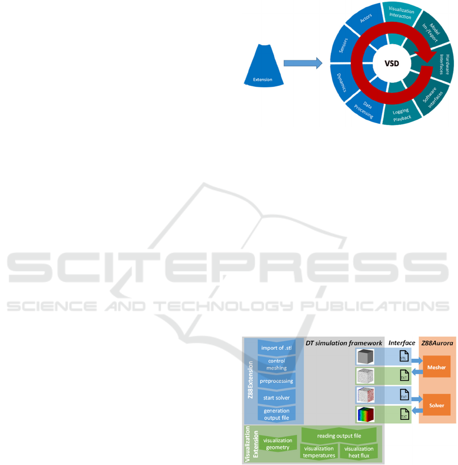
dynamically added to the program (see Figure 2).
Nevertheless, consequences caused by thermal
impact cannot be considered yet and thus need to be
integrated in the DT simulation framework.
There are many computational tools being able to
analyse the effect of thermal impact on components.
A thorough analysis of different FEA software was
performed before choosing a certain program. The
selection criteria were accessibility, usability (i.e.
documentation), accuracy, functionality and – of
course – compatibility, as an interaction with the DT
simulation shall be implemented. Finally, defining an
evaluation scheme and distributing points from 1-3
for the different criteria, the open source software
Z88Aurora (Z88, 2023) was chosen.
Figure 2: The VSD microkernel structure of the DT
simulation framework enables integration of new
functionalities via extensions (cf. Rossmann et al., 2013).
4.2 Implementation
The exchange of characteristic variables between the
DT and the Thermal Simulation is implemented via
an interface (see Figure 3). The relevant pieces of
information for the respective models are transferred
via files (.stl for geometry, .txt for FEA-relevant
information and visualization-input). The files have
the syntax the Thermal Simulation software
Z88Aurora requires. The generation and processing
of the files (i.e. the interface) is controlled by the DT
simulation framework. Two extensions were
implemented that integrate the new functionalities:
Figure 3: Design of the interface. The exchange of
characteristic variables is done with files (middle), which
contain the information for the mesher and solver of the
Thermal Simulation software Z88Aurora (right). The
interface is controlled by two extensions of the DT
simulation framework. One handles the communication to
the Thermal Simulation (i.e. the preprocessing;
corresponding functions marked in blue), the other one the
communication from the Thermal Simulation (i.e. the
visualizations; corresponding functions marked in green).
SIMULTECH 2023 - 13th International Conference on Simulation and Modeling Methodologies, Technologies and Applications
262

Z88Extension handles all communication from
the DT to the Thermal Simulation. Besides the
infrastructure for the geometry import via an
(possibly external generated) .stl-file, this
consists mainly of the preprocessing for the FEA
(i.e. meshing control, definition of boundary
conditions, start of the solver, generation of
output files). Z88Extension has its own GUI
element in the DT simulation framework, where
the user can set all relevant parameters.
VisualizationExtension handles all
communication from the Thermal Simulation to
the DT. This means in specific the processing of
the output files, i.e. the visualization of the
results from the Thermal Simulation.
5 EXEMPLARY USE CASE:
THERMAL SIMULATION OF
THE DT “VEHICLE AXLE”
In the following, the functions of the interface are
described on the basis of a thermal analysis of the
geometry shown in Figure 4 which can be interpreted
as a highly simplified version of a vehicle axle.
Figure 4: The imported geometry as base for the DT
“vehicle axle”.
This use case is only exemplary and shall
emphasize the functionality of the developed
integration of Thermal Simulations into a DT rather
than optimizing a real component. Thus, the object
size is rather small to keep the required computational
power low and thermal conductivity coefficients were
chosen, such that temperature differences and heat
flux could be particularly well illustrated.
Nevertheless, the structure contains subcomponents,
which are also used in the modeling of more complex
structures (cylinders, hollow cylinders, cuboids,
cavities). Furthermore, there is a certain reference to
real application scenarios: operation of a vehicle
generates heat due to friction of rotating shafts or
running gears, which then propagates along the axis.
5.1 Geometry Import and Meshing
The geometry is imported into the DT simulation
framework and thus the DT “vehicle axle” is created.
The geometry comes as an .stl file, which was created
externally with the help of CAD-software, following
the standard design process in mechanical
engineering.
First, the required density of the mesh has to be
defined. This can be easily done in the GUI of the DT
simulation framework by choosing different inputs
for the respective parameter in the Z88Extension.
Figure 5 shows the results for varying the parameter,
i.e. generating a finer mesh. The meshing of Figure
5 c) was taken for the following analyses, since the
FEA nodes are close enough to each other to map
temperature distributions and heat flux with a high
spatial resolution.
Figure 5: Nodes of the mesh for different values of the
respective parameter in the Z88Extension, which controls
the mesher from Z88Aurora out of the DT simulation
framework.
5.2 Temperature Analysis
First, simple temperature distributions are simulated
in the DT of the vehicle axle. Thus, specific
temperatures on the end faces of the axle are defined
via the DT simulation framework as boundary
conditions for the FEA. The GUI element of
Z88Extension provides the respective input options.
The upper boundary surface along the z-axis is
assigned a temperature of 𝑇
100°𝐶 , the lower
boundary surface a temperature of 𝑇
0°𝐶. Figure
6 a)-c) shows the resulting temperature distributions
for different thermal conductivity coefficients 𝜆
.
The increasing propagation of temperature within
the component resulting from an increasing thermal
conductivity coefficient can be easily seen. The
temperature variation is typical for this set of
boundary conditions and resembles the results of
other scientific publications (Prabhu et al., 2018).
Expanding the Scope and Increasing the Functionality of Digital Twins by Integrating Thermal Simulations
263
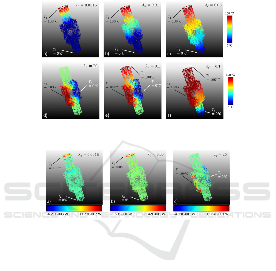
Figure 6: Temperature distributions of the DT are calculated for different boundary conditions (temperatures 𝑇
on different
surfaces) and different thermal conductivities 𝜆
.The upper row shows a typical temperature shift for increasing 𝜆. The lower
row shows mostly asymmetrical and thus more complex boundary conditions.
Figure 7: Heat flux in the DT for different boundary conditions (temperatures 𝑇
on different surfaces) and different thermal
conductivities 𝜆
.
In a second step, more complex boundary
conditions were applied, i.e. also other faces of the
axle got a defined temperature value as an input (see
Figure 6 d)-f)). While d) shows again a straight
temperature drop along the y-axis due to symmetrical
boundary conditions, the axle was exposed to
asymmetrical boundary conditions in e) and f).
Nevertheless, the resulting temperature distributions
are still reasonable (e.g. the similar temperature of the
connection between the upper cylinder and the cuboid
in e)).
In a last step, the temperature distributions were
calculated in a “pure FEA” in Z88 without the DT
simulation framework. The results were the same in
both cases.
5.3 Heat Flux Analysis
For an exemplary analysis of heat flux, the boundary
conditions of the temperature analyses were taken. In
Figure 7, the colours code for the heat flux balances
of the nodes. In the following, we define a positive
heat flux balance such that the amount of outgoing
heat fluxes exceeds the amount of incoming heat
fluxes. Figure 7 a) shows the heat flux balances of the
boundary conditions from Figure 6 a). The colour
gradient illustrates that changes only occur in the
upper cylindrical subbody. Due to the constant
temperature in the lower part of the axle, this was
expected. Figure 7 b) shows the heat flux distribution
corresponding to Figure 6 c). In contrast to the
previous heat flux distribution, the temperature
changes now also reach the lower face of the lower
cylindrical subelement, so there occur negative heat
flux balances. Figure 7 c) shows the heat flux
distribution of the temperature distribution shown in
Figure 6 d). A constant heat flux balance is again
established inside the body, but is no longer constant
on the boundary surfaces. This can be explained by
the cavity in the centre of the body, where no thermal
SIMULTECH 2023 - 13th International Conference on Simulation and Modeling Methodologies, Technologies and Applications
264

conductivity was specified, thus acting as an ideal
insulator.
5.4 Discussion
The first example of a DT with integrated Thermal
Simulations was created, examined and
thermodynamically analysed from within the DT
simulation framework.
Thus, the requirements of usability and
enhancement of time-management were met; both
secured by a central point of access for the whole
interaction with the FEA in the DT simulation
framework.
Besides, the resulting temperature distributions
and heat fluxes were the same in the DT simulation
framework as in a “pure FEA” only using the Thermal
Simulation software, which validates the interface
and the approach. Furthermore, they showed the
expected physical behaviour in accordance with other
Thermal Simulation related publications. Thus, also
the required preservation of quality of each
simulation method respectively was validated.
6 CONCLUSION
The aim of this work was the integration of Thermal
Simulations via FEA into an existing DT simulation
framework and thus expanding the scope of DTs.
In the development of the concept for this
integration, a special focus was set on the general
usability and validity. Thus, the DT environment
served as access point to conduct Thermal
Simulations of defined components. This concept
also optimizes time management, as this can be done
when critical situations occur in the application
scenario (contrary to performing an FEA at every
time step).
For the specific implementation, new extensions
for DTs were developed, which manage the
externally performed Thermal Simulations with
Z88Aurora. During the implementation, it was
necessary to convert the DT model to a model that is
FEA compatible. This was achieved by importing the
geometries from external .stl files. The
transformation of the models and the entire setup of
the Thermal Simulation was automated such that a
high degree of user-friendliness can be guaranteed.
The extensions currently include the calculation of
steady-state temperature and heat flux distributions,
where the starting point is a temperature distribution
on the surface.
7 OUTLOOK
Although a first approach of integration of Thermal
Simulations into a DT was successfully performed,
there are still opportunities for future work. For
example, more complex concepts concerning
thermodynamics could be integrated (e.g. thermal
loads due to thermal radiation, convection or electric
currents). In addition, the thermal processes might
result in geometric changes that have been neglected
so far. Thus, a combination with the structural
simulation framework for DT (Kaufmann et al.,
2018), (Kaufmann et al., 2019) will be interesting.
The same holds true for a specific application
scenario in space robotics, where heat influx is
already calculated in a DT, but not connected to FEA
(Rossmann et al., 2018).
REFERENCES
Baehr, H.D., Stephan, K. (2019). Wärme- und
Stoffübertragung. Berlin, Heidelberg: Springer Berlin
Heidelberg, 2019. isbn: 978-3-662-58441-5. doi:
10.1007/978- 3-662-58441-5_2.
Bu, X., Lin, G., Shen, X. et al. (2020). Numerical
simulation of aircraft thermal anti-icing system based
on a tight-coupling method. In: International Journal of
Heat and Mass Transfer 148, S. 119061.
Busch, M. (2012). Zur effizienten Kopplung von
Simulationsprogrammen. Dissertation. kassel
university press GmbH.
Cho, H., Cho, C. (2008). A study of thermal and mechanical
behaviour for the optimal design of automotive disc
brakes. In: Proceedings of the Institution of Mechanical
Engineers, Part D: Journal of Automobile Engineering
222.6, S. 895–915.
Deng, Y., Liu, X., Chen, S. et al. (2013). Thermal
optimization of the heat exchanger in an automotive
exhaust-based thermoelectric generator. In: Journal of
electronic materials 42.7, S. 1634–1640.
Grieves, M. (2016). „Origins of the Digital Twin Concept”.
Working paper, DOI: 10.13140/ RG.2.2.26367.61609.
Kaufmann D., Rast M., Rossmann J., (2017). Implementing
a new approach for bidirectional interaction between a
real-time capable overall system simulation and
structural simulations, Proc. 7th Int. Conf. Simulation
and Modeling Methodologies, Technologies and
Applications, Vol. 1, in De Rango, ¨Oren, Obaidat
(eds.), July 26th–28th, Madrid, Spain, SCITEPRESS,
pp. 114–125, ISBN 978-989-758-265-3.
Kaufmann, D, Roßmann, H.-J., (2018). Proof of Concept
for Using Non-Linear Springs to Integrate Deformable
Components' Behavior into a Real-Time Capable
Overall System Simulation for Robotics. IEEE/ASME
International Conference on Advanced Intelligent
Mechatronics Auckland, New Zealand, 1384-1389.
Expanding the Scope and Increasing the Functionality of Digital Twins by Integrating Thermal Simulations
265

Kaufmann, D., Rossmann, J. (2019). Integration of
structural simulations into a realtime capable Overall
System Simulation for complex mechatronic systems.
In: International Journal of Modeling, Simulation, and
Scientific Computing 10.02,S. 1940002.
Kral, C., Haumer, A., Lee, S.B. (2013) A practical thermal
model for the estimation of permanent magnet and
stator winding temperatures. In: IEEE Transactions on
Power Electronics 29.1, S. 455–464.
Musallam, M., Johnson, C.M. (2010). Real-time compact
thermal models for health management of power
electronics. In: IEEE Transactions on Power
Electronics 25.6, S. 1416–1425.
Panetta, K. (2018). „5 Trends in the Gartner Hype Cycle for
Emerging Technologies,“. [Online]. Available:
www.gartner.com/smarterwithgartner/5-trends-
emerge-in-gartner-hype-cycle-for-emerging-
technologies-2018. [Access 03/12/23].
Prabhu, L., Kumar, M. G., Prasanth, M. et al. (2018).
Design and analysis of different types of fin
configurations using ANSYS. In: International Journal
of Pure and Applied Mathematics 118.5, S. 1011–1017.
Rast, M. (2015). Domänenübergreifende Modellierung und
Simulation als Grundlage für virtuelle Testbeds,
Aachen: Dissertation, Apprimus Verlag.
Rossmann, J. and Schluse, M. (2011), „Virtual Robotic
Testbeds: A Foundation for e-Robotics in Space, in
Industry - And in the Woods,“ in Developments in E-
systems Engineering, Dubai, United Arab Emirates.
Roßmann, J., Schluse, M., Schlette, C., Waspe, R. (2013).
A New Approach to 3D Simulation Technology as
Enabling Technology for eRobotics. In Van Impe, Jan
F.M and Logist, Filip (Eds.): 1st International
Simulation Tools Conference & Expo 2013,
SIMEX’2013.
Rossmann, J., Stern, O., Kupetz, A., Osterloh, T. et al.,
(2018). The Virtual Testbed Approach towards
Modular Satellite Systems. The 69th International
Astronautical Congress, IAC, Bremen, Germany, ppl 1-
11.
Schluse, M., Priggemeyer, M., Atorf, L. and Rossmann, J.
(2018). „Experimentable Digital Twins - Steamlining
Simulation-Based Systems Engineering for Industry
4.0,“ IEEE Trans. Ind. Inf., Bd. 14, Nr. 4, pp. 1722-
1731.
Schmoll, R. (2015). Co-Simulation und Solverkopplung:
Analyse komplexer multiphysikalischer Systeme.
Dissertation. kassel university press GmbH.
Shafto, M., Conroy, M., Doyle, R., Glaessgen, E., Kemp,
C., LeMoigne, J. and Wang, L. (2010). „Draft
Modeling, Simulation, InformationTechnology &
Processing Roadmap,“ NASA, US.
Stettinger, G., Benedikt, M., Thek, N. et al. (2013). On the
difficulities of real-time cosimulation. In: COUPLED
V: proceedings of the V International Conference on
Computational Methods for Coupled Problems in
Science and Engineering: CIMNE, S. 989–999.
v.d. Broeck, C.H., Ruppert, L.A., Hinz, A. et al., (2017).
Spatial electro-thermal modelling and simulation of
power electronic modules. In: IEEE Transactions on
Industry Applications 54.1, S. 404–415.
Weid, J.B., (2021).
Anbindung thermischer
Simulationsmodelle an Digitale Zwillinge. Bachelor
Thesis. Kaufmann, D. (supervising assistant),
Rossmann, J. (supervising professor). Institute for Man-
Machine-Interaction, RWTH Aachen University.
Z88 (2023). Official Website. https://z88.de/z88aurora/.
[Access 03/12/23].
SIMULTECH 2023 - 13th International Conference on Simulation and Modeling Methodologies, Technologies and Applications
266
