
Simulation of Curvature Ductility of Reinforced Concrete Cantilever
Beam Under Variety of Section Ratio
Dewi Pertiwi
1
a
, Indra Komara
1,*
b
, Eka Susanti
1,2
c
, Heri Istiono
1,2
d
, Jaka Propika
1,2
e
,
Yanisfa Septiarsilia
1,3
f
, Dita Kamarul Fitria
1,3
g
and Firdhian Vima Rizaldy
1
1
Civil Engineering Department, Institute Technology Adhi Tama Surabaya,
Jl. Arif Rahman Hakim 100, Klampis Ngasem, Sukolilo, Surabaya, East Java, Indonesia
2
Civil Engineering Department, Petra Christian Unviersity,
Jl. Siwalankerto No.121-131, Siwalankerto, Surabaya, 60236, East Java, Indonesia
3
Civil Engineering Department, Institut Teknologi Sepuluh Nopember,
Jl. Teknik Kimia, Keputih, Sukolilo, Surabaya, East Java, Indonesia
jakapropika@itats.ac.id, yanisfa.septi@itats.ac.id, ditaka.fitriyah@itats.ac.id, firdhian@gmail.com
Keywords: Curvature Ductility, Moment Curvature, Reinforced Concrete Cantilever Beam, Numerical Analysis,
Structural Evaluation
Abstract: The purpose of this research is to look into the effects that the ductility of reinforced concrete cantilever beams
has on their curvature. A numerical program was simulated to estimate moment-curvature and available
curvature ductility of reinforced concrete cantilever beams with or without axial loads. The study evaluate
five cantilever beams with various factors were examined. Concrete strength, the quantity of longitudinal
reinforcement, and the spacing of transverse reinforcement are the factors that are measured. Beam geometry,
material characteristics, and weight make up the input. properties of the retrofitted material by using a variety
of different approaches. A confined stress-strain curve was generated for concrete using SAP2000's adopted
methods, in the same way that a steel stress-strain model was generated. From the evaluation, the curvature
ductility increases with the longitudinal reinforcement and concrete strength with it representing by the
distance length of cantilever beam. However, there is no discernible relationship between the curve ductility
and the spacing of the transverse reinforcement.
1 INTRODUCTION
When structural integrity depends on resistance to
brittle failure during flexure, reinforced structures'
ductility is a desirable characteristic. Plastic joints
placed strategically throughout the structural frame
can be used to create a ductile behavior in a structure
(Marta, 2014). These are made to be sufficiently
ductile to withstand structural failure once the
material's yield strength has been reached. Based on
the configuration of the moment-curvature relations,
a
https://orcid.org/0009-0008-1010-1872
b
https://orcid.org/0000-0001-7260-0855
c
https://orcid.org/0009-0009-4773-729X
d
https://orcid.org/0009-0002-7220-3846
e
https://orcid.org/0009-0008-5622-9513
f
https://orcid.org/0009-0008-4486-1810
g
https://orcid.org/0009-0008-9954-0184
the available ductility of plastic hinges in reinforced
concrete is found (Arslan and Cihanli, 2011).
Ductility is defined as the ability to endure
deformations without significantly reducing the
member's flexural capacity (Szerszen, Szwed and Li,
2007). According to the findings of previous study,
this deformability is affected by factors such as the
tensile reinforcement ratio, the quantity of
longitudinal compressive reinforcement, the degree
of lateral tie, and the strength of the concrete (Park
and Paulay, 1975). The ductility of a reinforced
310
Pertiwi, D., Komara, I., Susanti, E., Istiono, H., Propika, J., Septiarsilia, Y., fitria, D. and Rizaldy, F.
Simulation of Curvature Ductility of Reinforced Concrete Cantilever Beam Under Variety of Section Ratio.
DOI: 10.5220/0012104300003680
In Proceedings of the 4th International Conference on Advanced Engineering and Technology (ICATECH 2023), pages 310-315
ISBN: 978-989-758-663-7; ISSN: 2975-948X
Copyright
c
2023 by SCITEPRESS – Science and Technology Publications, Lda. Under CC license (CC BY-NC-ND 4.0)
concrete section could be represented as curvature
ductility, see Equation (1).
𝜇
𝜙
𝜙
(1)
𝑀
𝐴
𝑓
𝑑
"
(2)
𝜙
𝜀
1𝑘
𝑑
𝑓
𝐸
1𝑘
𝑑
(3)
𝑀
0.85
𝑓
𝑎𝑏
𝑑𝑎
2
𝐴
′
𝑓
𝑑𝑑
(4)
𝜙
𝜀
𝑐
𝜀
𝛽
𝑎
(5)
Where
𝑎
𝐴
𝑓
𝐴
′
𝑓
0.85
𝑓
′
𝑎
(6)
𝑘
𝜌𝜌
𝑛
2𝜌
𝜌
𝑑
𝑑
𝑛
𝜌𝜌
𝑛
(7)
𝜌
𝐴
𝑏𝑑
(8)
Equation (1) to (8) presenting the curvature
parameter in accordance with (Park and Paulay,
1975), where 𝜇
is curvature ductility and
respectively, 𝜙
and 𝜙
, are curvature ultimate and
curvature point when the reached yield strength.
Normally, 𝜙
defined as the effect of the ultimate
strain from concrete compression and 𝜙
defined as
the influence of the yield strength of reinforcement
steel on the calculation of 𝜙
. The vast majority of
the regulations on the design curvature analysis stated
that the yield curvature of a reinforced concrete beam
should be taken when the tension steel first yields.
This condition, which may be derived from Equation
(2), and (3). Where k, 𝜌 is the tensile reinforcement
ratio and 𝜌
is the compression steel ratio. In addition,
n is the modular ratio were taken from the comparison
of modulus elasticity of steel over modulus elasticity
of concrete. 𝑑
"
is centroid distance over compressive
force in steel and centroid of tension over concrete.
Furthermore, to understand the ultimate
curvature, Equation (4) – (5) are used. In this stage,
evaluate the capacity of reinforced concrete where the
crushing of RC section occurred. 𝑓′
denoted as
compressive strength, 𝑓
denoted as yield strength,
where 𝛽
is the depth of equivalent rectangular stress
block. The design parameters in accordance with the
SNI 2847-2019 (Badan Standardisasi Nasional,
2019a) and ACI 318-71 (American concrete Institute,
2014) conservatively recommend stress block 0.003.
Some researchers identified the nominal value of
ultimate concrete strain (𝜀
) required to compute
Conventional Curvature Ductility Factor for
unconfined concrete is 0.0035, while it is implicitly
greater for confined concrete.
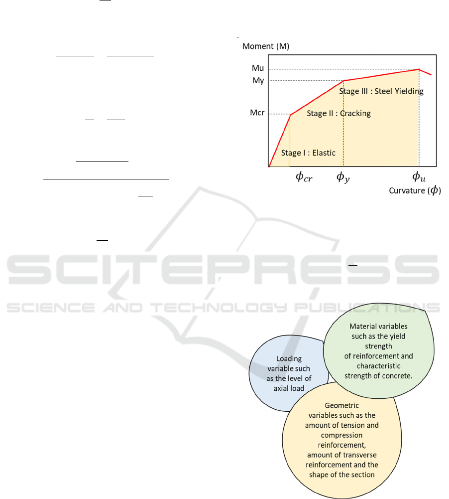
Figure 1: A moment curvature relationship under three
different stage condition (American concrete Institute,
2014).
𝐸𝐼𝑀𝑅
𝑀
𝜑
(9)
Where EI is the section flexural rigidity.
Figure 2: Curvature behaviour parameter (Olivia, Riau and
Mandal, 2005).
Theoretical moment-curvature analysis for
reinforced concrete structural components can be
performed to determine the available flexural strength
and ductility, provided the stress-strain relations for
Simulation of Curvature Ductility of Reinforced Concrete Cantilever Beam Under Variety of Section Ratio
311
both concrete and steel are known (Arslan and
Cihanli, 2011; Zhou, He and Liu, 2014). Curvature
and the bending moment of the section for a given
load raised to failure can be used to calculate the
moment-curvature relationship (Fischer and Li, 2003,
2003). The illustration of trilinear moment-curvature
in accordance with Park and Paulay can be seen in
Figure 1 (Park and Paulay, 1975). From the
illustration, the curvature classified by three different
straight stages line represent elastic conditions, after
first cracking and yielding. It is also illustrated by
classic elastic Eq. (9), relationship between moment
and curvature. Some past works also investigated
based on variety of concrete materials, which is not
included in the research. The concrete material will
also represent a different behaviour (Komara et al., no
date; Kartiko et al., 2021; Pertiwi et al., 2023)
The study evaluates five different cantilever
beams with the variable of section ratio as the demand
of section dimension which is normally used in the
midrise building. The empirical model was developed
to consent the ductility analysis. Some identifications
also included into this model to corroborate findings.
2 RESEARCH METHODS
The study was carried out by determining the range
of parameters used in the cantilever beam elements.
These parameters came in the sectional beam
property. The length of beam implied as 3 m length
and this length placed as the current case study from
office building located in East Sumatera. The
simulation appears in the same condition, elevate to
14.4 m with four lever stories with 825 m
2
. The
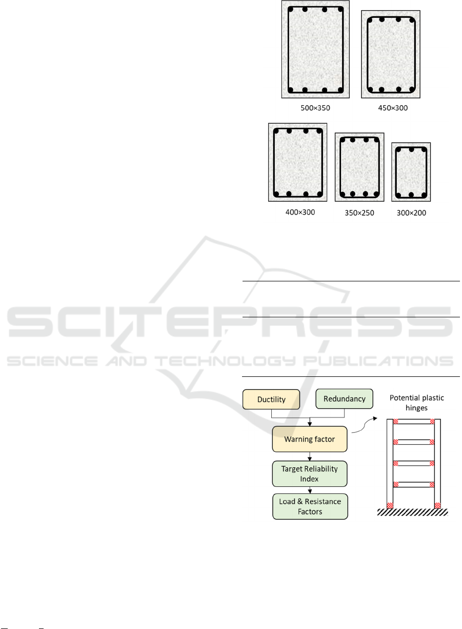
section model is in accordance with the Figure 3
where the variation presented in Table 1. The f’c used
in this simulation is factually the same for all beam
section, 30 MPa. The phase of evaluation illustrates
in Figure 4.
To identify loading mechanism, SNI 1726-2019
(Badan Standardisasi Nasional, 2019b) is used,
followed by earthquake regulation SNI 1726-2019
and concrete SNI 2847-2019 (Badan Standardisasi
Nasional, 2019a). After clarifying all preliminary
analysis, structural analysis program using SAP2000
is conducted (2000, 2008; Interface, Implemented
and Implemented, 2013). This study relates to the
implementation of load & resistance factors of
cantilever beam can be seen in Figure 4 and the 3D
model in SAP200 can be accessed on Figure 5.
Modification load factor is assigned with the value as
𝑔
9.813.27.
Figure 3: Cross section cantilever beam [unit: mm].
Table 1: Reinforcement proportion varied by length
of cantilever beam.
Section
ratio
(len
g
th)
Section
dimension
(mm)
Rein.
ratio
Reinforcement
section area
(mm)
L/6 500×350 0.012 1860
L/7 450×300 0.012 1412
L/8 400×300 0.012 1231
L/9 350×250 0.012 874
L/10 300×200 0.012 578
Figure 4: structure reliability concept (Frangopol, Lin and
Estes, 1997).
ICATECH 2023 - International Conference on Advanced Engineering and Technology
312

Figure 5: Three-dimensional illustration building modelling
using SAP2000.
Table 1 inform the distribution of reinforcement ratio
designed into cantilever beam. From that evaluation,
the reinforcement bar used for mid and start point,
respectively 4D15, 150-∅12 and 4D15, 180-∅12.
The total dead load (DL) according to the office
building summarized with the total 1.5 kN/m2 and
DL for roof particularly given less, with 0.65 kN/m2.
The life load (LL) is given higher than DL, count as
2.5 kN/m
2
and for roof, LL 1.0 kN/m
2
. The
fundamental period parameter considering the
location, with the detail data are S
s
= 0.29 with F
a
=
0.9 and S
1
=0.25 and F
v
= 0.8, is 0.7593.
The computational approach for deriving the
curvature ductility from the moment curvature
behavior of the cross section is as follows, see Eq. 10,
assess the ultimate axial load, and then derive the
curvature ductility (Badan Standardisasi Nasional,
2013).
𝑃
𝐴
𝐴
𝑚𝑎𝑥.𝑠𝑡𝑟𝑒𝑠𝑠
𝐴
𝑓
(10)
𝐴
is the gross area of confined concrete, 𝐴
is the
area of longitudinal steel, 𝑓
is the yield strength.
The strain at the extreme compressive fibre is then
analysed as if the section were applied with a single
axial load without any moment (Mihashi and Leite,
2004; Yu et al., 2017). For the value of fibre strain,
the strain profile is created. It is presumable that strain
varies linearly with beam cross section. As shown in
Figure 4, the section is cut into rectangular strips to
estimate compressive forces in concrete. The relevant
stress-strain models are used to compute the
corresponding stresses in concrete and steel.
Calculations are made for the internal forces
supporting steel (Gagg, 2014; Jensen, Kovler and
Belie, 2016).
Figure 6: Stage of evaluation moment curvature (Zhou, He
and Liu, 2014).
3 RESULTS AND DISCUSSION
In order to conduct an analysis of the 5 beams, the
numerical model was utilized. The output of the
program comprises of numerical results as well as
values for the curvature ductility. The ductility
calculation took into account the parameters that were
taken into consideration. In this section, it will discuss
the effects that the key factors have on the moment-
curvature curves. The stage of the evaluation can be
seen in Figure 6. A comparison of the moment-
curvature relationship for five beams is provided in
Figure 7. These beams have the same concrete
strength and longitudinal reinforcement but differing
confinement reinforcement spacing. When a segment
is constricted, both the ultimate compressive strain
and the ductility of the material are increased. The
Simulation of Curvature Ductility of Reinforced Concrete Cantilever Beam Under Variety of Section Ratio
313

yield and maximum moment capacity of the section
are unaffected by the transverse steel because the
stress-strain model used in the numerical analysis
assumes that the shape of the initial ascending
segment is unaffected by the amount of transverse
steel. Transverse steel reinforcement does not change
yield curvature. However, compressive strain
increases curvature.
It is also determined that closer spacing delays the
buckling of the compressive reinforcement but has no
effect on the material's ductility because failure
occurs in tension steel. In light of this, the researchers
conducting the present study have concluded that a
tighter confinement spacing is ineffective. Figure 7
also shows that parameter of ρ’/ ρ classifying from ¼
to 1.0 which come to be one of the important aspects.
Cantilever beam L/10 shows the lowest moment
curvature ductility, relating to the parameter of
longitudinal reinforcement. The reason is considerate
by the increase amount of tension steel as well as the
depth of the neutral axis. When yield is reached in
longitudinal steel, the stress remains fixed, and the
depth of the neutral axis increases with curvature.
When the strain at the maximum compressive fiber of
concrete is fixed at ultimate condition, the curvature
at ultimate condition reduces.
Figure 7: Moment curvature curves for cantilever beam
with different length.
On the other hand, cantilever beam L/6 illustrates
to have the highest moment curvature ductility. It is
informed that having the very low amount of tension
steel. The breaking of tension steel is a possibility that
could lead to the ultimate situation. In this scenario,
the strain on the tension steel is held constant at the
ultimate condition; hence, the curvature at the final
condition grows. As a consequence of this, the
ductility of the curvature improves in proportion to
the reduction in the amount of tension steel. When
yield is reached in longitudinal steel, the stress
remains fixed, and the depth of the neutral axis
increases with curvature. When the strain at the
maximum compressive fiber of concrete is fixed at
ultimate condition, the curvature at ultimate condition
diminishes.
Curvature ductility decrease gradually as the
variable length is extended, L/6 – L/10. It needs to
improve the confined parameter and also the relation
of various steel reinforcement ratio to accommodate
the difference.
4 CONCLUSIONS
This research is evaluated on verifying the model of
cantilever reinforced concrete beam using SAP2000,
which indicate the value of moment curvature. This
such evaluation to anticipate the fracture condition to
the structure. The modelling process include 5
different cantilever beams classified by length
different. According to the findings, the effect of
materials properties and its geometric on the
curvature ductility of cantilever reinforced concrete
under this case study is very low. As expected, it was
found that length variable determines the value of
moment curvature. The availability of curvature
decreased by the length of span of cantilever beam
which is composed of longitudinal reinforcement.
One that should be noted, there is no significant affect
increase on the confined reinforcement while the
model and the numerical analysis having a good
agreement.
ACKNOWLEDGEMENTS
The author wishes to express their gratitude to the
Ministry of Research, Technology, and Higher
Education of the Republic of Indonesia for their
financial assistance with this research project, as well
as for the support and facilities that were made
available to them. In addition, we would like to
extend our gratitude to ITATS for providing support
within the scope of the study project.
REFERENCES
2000, S. (2008) ‘SAP2000 Basic Analysis Reference
Manual’, in Computers & Structures.
-
500
1000
1500
2000
2500
3000
3500
0 0,0001 0,0002 0,0003
Moment M (kNm)
Curvature φ (1/mm)
L/6
L/7
L/8
L/9
L/10
ICATECH 2023 - International Conference on Advanced Engineering and Technology
314

American concrete Institute (2014) Building Code
Requirements for Structural Concrete, American
Concrete Institute.
Arslan, G. and Cihanli, E. (2011) ‘Curvature ductility
prediction of reinforced high ‐ strength concrete beam
sections’, 3730. doi: 10.3846/jcem.2010.52.
Badan Standardisasi Nasional (2013) ‘Beban minimum
untuk perancangan bangunan gedung dan struktur lain.
SNI 1727:2013’, in Bandung: Badan Standardisasi
Indonesia, p. 196. Available at: www.bsn.go.id.
Badan Standardisasi Nasional (2019a) ‘Persyaratan Beton
Struktural Untuk Bangunan Gedung Dan Penjelasan
Sebagai Revisi Dari Standar Nasional Indonesia. SNI
03-2847:2019’, Badan Standarisasi Nasional, (8), pp.
1–695.
Badan Standardisasi Nasional (2019b) ‘Sni 1726-2019’,
Tata Cara Perencanaan Ketahanan Gempa Untuk
Struktur Bangunan Gedung dan Non Gedung, (8), p.
254.
Fischer, G. and Li, V. C. (2003) ‘Deformation behavior of
fiber-reinforced polymer reinforced engineered
cementitious composite (ECC) flexural members under
reversed cyclic loading conditions’, ACI Structural
Journal, 100(1), pp. 25–35. doi: 10.14359/12436.
Frangopol, D. M., Lin, K.-Y. and Estes, A. C. (1997)
‘Reliability of Reinforced Concrete Girders under
Corrosion Attack’, Journal of Structural Engineering,
123(3), pp. 286–297. doi: 10.1061/(asce)0733-
9445(1997)123:3(286).
Gagg, C. R. (2014) ‘Cement and concrete as an engineering
material: An historic appraisal and case study analysis’,
Engineering Failure Analysis. Elsevier Ltd, 40, pp.
114–140. doi: 10.1016/j.engfailanal.2014.02.004.
Interface, U., Implemented, E. and Implemented, E. (2013)
‘SAP2000® (Version 16.0.0) Release Notes ©’, pp. 1–
21.
Jensen, O. M., Kovler, K. and Belie, N. De (2016) Concrete
with Supplementary Cementitious Materials.
Kartiko, A. S. et al. (2021) ‘Analisis Geometri Bangunan
Terhadap Kinerja Seismik Menggunakan Direct
Displacement Based Design Method’, 04(September).
Komara, I. et al. (no date) ‘Experimental investigations on
the durability performance of normal concrete and
engineered cementitious composite’.
Marta, S. (2014) ‘Shear failure mechanism in concrete
beams’, Procedia Materials Science. Elsevier B.V.,
3(Vd), pp. 1977–1982. doi:
10.1016/j.mspro.2014.06.318.
Mihashi, H. and Leite, J. P. D. B. (2004) ‘State-of-the-art
report on control of cracking in early age concrete’,
Journal of Advanced Concrete Technology, 2(2), pp.
141–154. doi: 10.3151/jact.2.141.
Olivia, M., Riau, U. and Mandal, P. (2005) ‘Curvature
Ductility of Reinforced Concrete Beam’, Jurnal Teknik
Sipil, 6(June), p. 13.
Park, R. and Paulay, T. (1975) Reinforced Concrete
Structure Strength and Deformation of Members with
Shear
.
Pertiwi, D. et al. (2023) ‘Performance of High-Strength
Concrete Properties for Two Locally Available
Aggregates : Partial Gradation Approaches’, 20(3).
Szerszen, M. M., Szwed, A. and Li, V. C. (2007) Flexural
Response of Reinforced Beam with High Ductility
Concrete Material, Brittle Matrix Composites 8.
Woodhead Publishing Limited. doi:
10.1533/9780857093080.263.
Yu, K. et al. (2017) ‘A strain-hardening cementitious
composites with the tensile capacity up to 8%’,
Construction and Building Materials. Elsevier Ltd,
137, pp. 410–419. doi:
10.1016/j.conbuildmat.2017.01.060.
Zhou, J., He, F. and Liu, T. (2014) ‘Curvature ductility of
columns and structural displacement ductility in RC
frame structures subjected to ground motions’, Soil
Dynamics and Earthquake Engineering. Elsevier, 63,
pp. 174–183. doi: 10.1016/j.soildyn.2014.03.009.
Simulation of Curvature Ductility of Reinforced Concrete Cantilever Beam Under Variety of Section Ratio
315
