
Experimental Study to Analyze the Effect of Fan Speed on Energy
Efficiency in Open Cathode Pem Fuel Cells
Akhmad Fahruzi
1,* a
, Katherin Indriawati
1,† b
and Mat Syai’in
2,‡ c
1
Department of Engineering Physics, Institut Teknologi Sepuluh Nopember, Surabaya, Indonesia
2
Ship Electrical Engineering, Politeknik Perkapalan Negeri Surabaya, Surabaya, Indonesia
Keywords: Open Cathode, PEMFC, Air Supply, Stack Temperature.
Abstract: Open Cathode PEM Fuel Cells (OCPEMFCs) are widely used, performance OCPEMFCs is affected by
operating conditions such as temperature, humidity, air flow rate. In this paper, an experimental investigation
has been carried out on the effect of fan speed on stack performance and efficiency of energy that using
commercially from OCPEMFCs system 1kW. During the experiment, temperature, voltage and current of
stack will be monitored and recorded under various load level. It is referred that the optimal fan speed through
the duty cycle setting can reduce auxiliary power consumption. The results are compared with the commercial
system. The experimental results show that by loading a fuel cell gradually from 100 - 500W will produce the
optimum duty cycle values of the fans were obtained, namely 20, 30, and 40% respectively. From the duty
cycle value, the stack performance is still in a stable condition, it can be seen from the range of stack voltage
during the experiment that still allowed with nominal voltage range. Meanwhile, a comparison of the stack
power output between the fuel cell and the Company's and the Lab's system shows that the fuel cell and the
Lab's system have a smaller difference of about 8 W.
1 INTRODUCTION
Fuel cells are a type of new renewable energy that can
convert chemical energy into DC electricity through
the reaction of hydrogen and oxygen gases(Mousavi
& Mehrpooya, 2021)(Souleman et al., 2009). The fuel
cell will generate electricity continuously as long as
the supply of hydrogen gas to the anode channel and
oxygen to the cathode channel is full. Fuel cells are
becoming popular as an alternative energy source
because they have high power density, zero-
emissions, and low operating temperatures(Fernandez
et al., 2020). There are several types of fuel cells, such
as Solid Oxide Fuel Cells (SOFC), Direct Methanol
Fuel Cells (DMFC), and Polymer Electrolyte
Membrane or Proton Exchange Membrane (PEM)
Fuel Cells. Of these types of fuel cells, in general they
have several similarities, namely having an anode and
cathode channels as a fuel supply. While the PEMFC
type fuel cell has several advantages compared to
a
https://orcid.org/0000-0001-6650-2183
b
https://orcid.org/0000-0002-9333-088X
c
https://orcid.org/0000-0001-7459-4487
other types such as fast dynamic response and low
operating temperature(Pangaribowo et al., 2020)
(Meng et al., 2022).
PEMFCs with open cathode technology
(OCPEMFCs) have been widely used, especially in
electronic devices that are portable applications
because of their small shape and simple stack
design(Ling et al., 2016)(Zhao et al.,
2020)(Shahsavari et al., 2012). In OCPEMFCs,
electric fans are used to provide oxygen supply from
the surrounding air and control the stack
temperature(Huang et al., 2014). The advantage of
OCPEMPCs is their simple and lightweight fuel cell
configuration. This is because several sub systems
such as cooling, humidifier and inlet pressure control
have been eliminated(Kurnia et al., 2021). However,
the weakness of the open cathode type fuel cell is that
the performance of the fuel cell is affected by the
thermodynamic conditions of the surrounding
environment and for a higher current density, the
supply of reactants at the cathode may not be sufficient
336
Fahruzi, A., Indriawati, K. and Syai’in, M.
Experimental Study to Analyze the Effect of Fan Speed on Energy Efficiency in Open Cathode Pem Fuel Cells.
DOI: 10.5220/0012109000003680
In Proceedings of the 4th International Conference on Advanced Engineering and Technology (ICATECH 2023), pages 336-341
ISBN: 978-989-758-663-7; ISSN: 2975-948X
Copyright
c
2023 by SCITEPRESS – Science and Technology Publications, Lda. Under CC license (CC BY-NC-ND 4.0)

to produce an optimal electrochemical reaction and
the heat generated by the reaction cannot be removed
effectively(Baik & Yang, 2020). However, in recent
years, the demand for OCPEMFCs as a source of
stationary energy and portable applications is growing
rapidly(Gopi et al., 2020).
The proton conductivity of the membrane is the
main factor affecting OCPEMFCs performance,
where the ionic conductivity depends on the amount
of water content in the membrane, while the amount
of water content is affected by flow rate, humidity and
temperature(Zhang et al., 2008). Pei et al.(Pei et al.,
2014) shows that high stack temperatures can cause
evaporation of water in the membrane, causing
dehydration of the membrane which results in
decreased stack performance.
Sasmito et al.(Sasmito et al., 2010) have studied
several factors that affect operating point and stack
temperature such as fan power, single fan or fans in
series, stack length, separate air-coolant channels.
Meyer et al.(Meyer et al., 2015) showed that parasitic
loads such as air blowers can affect stack performance
and temperature distribution. For the purposes of
energy efficiency, the effect of parasitic loads needs to
be investigated further. Analysis of how much the
minimum cooling air flow is needed to maintain the
temperature when there is a change in load from the
fuel cell, is a problem that needs to be answered.
From the problems above, this paper reports the
results of an experimental investigation on the effect
of fan speed on energy efficiency produced by
OCPEMFCs with various power loads where the fan
is used to maintain the stack temperature to be in
permissible conditions. The net power output, stack
temperature and energy efficiency produced
experimentally (which is named as the Lab's system)
will be compared with the company's system.
2 EXPERIMENTAL
2.1 Experimental Setup
The open cathode PEMFC used in this experiment is
A commercially available fuel cell system (G-HFCS-
1kW36V hydrogen fuel cell system produces 1000
W), which is named as the Company's system in this
paper, and it consists of an electrical fan, an inlet
valve, a purge valve and a control unit(Dr. Colleen
Spiegel, 2019). The electrical fan used consists of two
fans with a voltage specification of 12V and a current
of 4.1A for each fan. Figure 1. is a schematic diagram
of experimental setup.
Fuel CellHydrogen tank
Controller
Fan
Computer
Load
(net Power)
Pressure Transmitted
Buck boost
converter
Current
Sensor
Figure 1: A Schematic of experimental setup.
The hydrogen pressure entering the anode side
(stack inlet) is controlled by a pressure regulator at 5
psi and also a temperature sensor which is used to
measure the stack temperature. In addition, there are
voltage and shunt current sensors that are used to
monitor the fuel cell voltage and current. The fuel cell
power levels were applied using six light bulbs
connected to the dimmer shield as various power
loads. The microcontroller unit (MCU) is used to
control the fan speed. using pulse width modulation
signal and data acquisition sensors. All information is
processed by the microcontroller and sent to the
computer which is then processed and recorded using
Visual Basic.net software.
Table 1: Specification of fuel cell system (G-HFCS
1kW36V) (Dr. Colleen Spiegel, 2019).
Description Values
Nominal Power 1000W
Nominal Voltage 36V
Nominal Current 27.8A
DC voltage Range 32-55V
Hydrogen Pressure 0.004 – 0.006 MPa
Hydrogen Consumption 11.7 L/min (at
nominal power)
Ambient temperature -5 to +35
o
C
Ambient Humidity 10% RH to 95%RH
Storage Ambient Temperature -10 to 50
o
C
2.2 Experiment Procedure
In this study, the fuel cell system was operated at
various stack power outputs, ranging between 100
and 500 W. Fan speed was controlled by varying the
duty cycle from 10-60% with a delay every minute on
each stack power output, where the smaller the duty
cycle, the lower the fan speed, which means the lower
the power consumption. During operation, the value
of voltage, current, temperature of stack and duty
cycle will be recorded, while the pressure of hydrogen
gas flowing into the anode channel is set to be
constant at 5 psi.
Experimental Study to Analyze the Effect of Fan Speed on Energy Efficiency in Open Cathode Pem Fuel Cells
337
To find the optimal fan duty cycle value, namely
the fuel cell is given a certain load constantly, then
the duty cycle value is increased at each step with an
initial value of 10%, 20%, 30% to 60%. Furthermore,
observing the stack temperature, the optimal duty
cycle value is obtained if the stack temperature value
has started to decrease but also considering the stack
temperature value is still within the range of
permitted conditions, namely below 50
o
C.
In efficiency analysis of the fuel cell system, the
net power output (P
net
) between our Lab's system was
compared with that of the company's system, where
P
net
is the difference between the stack power output
(P
stack
) and the power consumption of the auxiliary
components (P
auxiliary
) (Bizon, 2014).
P
net
= P
stack
- P
auxiliary
(1)
For the operation fan speed, controller provides
the supply voltage with pulse width modulation
(PWM) under duty cycle setting. A duty cycle (D) is
expressed as
D = t
pulse
/ t
cycle
(2)
Where t
pulse
is the duration of the pulse width and t
cycle
is the signal period (Brown, 1990).
3 RESULT AND DISCUSSIONS
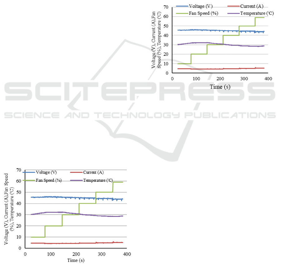
Fig. 2 shows the variations in the temperature,
voltage, and current of the OCPEMFC stack of the
Company's system under various load levels, which
auxiliary components of the Company’s system like
two electric fans that controlled by using built-in
controller so the user cannot control its velocity. It
can be seen that stack temperature and constant fan
speed to keep stack temperature below 50
o
C.
Figure 2: Distribution of temperature, voltage and current
of company’s System under variable speed fan.
The first experiment was the fuel cell was loaded
with 100 W where variations in the temperature,
current, and voltage of the OCPEMFC stack of the
Lab's system as shown in Figure 3. When the duty
cycle of the fan was 10%, the stack temperature
increased from 30 - 33
o
C in about 1 minute. When the
duty cycle changes to 20%, the stack temperature is
maintained constant at 33
o
C and the stack voltage
value is still maintained constant at 47 V. Next, when
the duty cycle is 30%, the stack temperature drops,
but the stack voltage also drops, this is due to there is
an additional load due to the faster fan speed. From
these results it can be stated that the optimal duty
cycle value for a 100W load is 20%.
Figure 3: Distribution of temperature, voltage and current
under variable speed fan with fuel cell loads 100W.
Figure 4 is the result of the fuel cell experiment
with a load of 200W. From the figure it can be seen
that when the duty cycle is less than 30%, the stack
temperature rises from 31-37
o
C for 140 seconds. This
phenomenon shows that the fan speed at a duty cycle
below 30%, the stack temperature will continue to
rise if it is operated for a long time and will cause a
decrease in fuel cell performance and result in
damage to the fuel cell membrane. When the duty
cycle is 30%, the stack temperature starts to drop and
at that time the stack voltage value is 45V. From this
experiment it can be concluded that the optimal value
of the duty cycle of the fan speed for a load of 200W
is 30%.
When the fuel cell is loaded with 300W as shown
in Figure 5, the stack temperature increases rapidly
from 33-43
o
C for 120 seconds with duty cycle values
of 10% and 20%. The stack temperature starts to drop
at 30% duty cycle with a constant stack voltage of
40V. From these results, that the optimal duty cycle
at 300W load is 30% and this is the same as at 200W
load.
ICATECH 2023 - International Conference on Advanced Engineering and Technology
338

Figure 4: Distribution of temperature, voltage and current
under variable speed fan with fuel cell loads 200W.
Figure 5: Distribution of temperature, voltage and current
under variable speed fan with fuel cell loads 300W.
When the fuel cell is loaded with 400W, as shown
in Figure 6, the stack temperature continues to rise
when the duty cycle value is 10-30% with a value
close to 45
o
C, but when the duty cycle value is that
the stack voltage constant value is around 40V. When
the duty cycle is increased to 40%, the stack
temperature drops, followed by the stack voltage to
38V. So that the optimal duty cycle value is obtained
when the 400W load is 40%.
When the fuel cell is loaded with 500W as shown
in Figure 7, the fuel cell experiences a transient with
the stack voltage rising from 33V to a peak of 40V for
30 seconds. Besides that, the duty cycle of 10%, 20%,
30% is not able to reduce the stack temperature, as a
result, the stack temperature continues to increase
from 29 –44
o
C. When the duty cycle is 40%, the stack
temperature has decreased and the stack voltage has
reached a steady state point of 38V even though the
duty cycle value has been increased to 60%. From this
experiment it shows that the optimal duty cycle value
with a 500W load is 40% and this value is the same
when the fuel cell load is 400W.
Figure 6: Distribution of temperature, voltage and current
under variable speed fan with fuel cell loads 400W.
Figure 7. Distribution of temperature, voltage and current
under variable speed fan with fuel cell loads 500W.
Based on the experimental results above, it shows
that the stack temperature is very dependent on the
fuel cell load, the greater the fuel cell load, the greater
the stack temperature. In addition, the stack voltage at
steady state conditions also decreases when the load
increases (see Figure 8). Figure 8 also shows the stack
voltage to be a momentary drop caused by purging
activity. To increase fuel cell energy efficiency, apart
from maintaining the internal condition of the fuel
cell within the permitted area, it can also be done by
optimizing the power used to supply electronic
components such as electric fans which are used to
support the performance of the fuel cell or it is called
Auxiliary power consumption. As a result, the fan
needs to control its speed, where the size of the speed
is affected by the load from the fuel cell. Table 2
shows the conclusion of the results of the P
stack
comparison of the fuel cell between the Lab's System
and the Company's system during the experiment
with a load of 100-500 W.
Experimental Study to Analyze the Effect of Fan Speed on Energy Efficiency in Open Cathode Pem Fuel Cells
339

Figure 8: Comparison Stack Voltage under various
load of fuel cell.
Table 2: Comparison P
stack
fuel cell between Lab’s System
and Company’s system.
Fuel cell
loads
(Watt)
P
stack
of
Lab’s
system
(W)
P
stack
of
Company’s
system (W)
ΔP
stack
(W)
100 196.08 204.78 8
200 243.96 252.66 8.2
300 420 428.7 8.7
400 462.38 471.08 8.9
500 610.5 619.2 9
4 CONCLUSIONS
Based on the experimental results of setting the fan
speed manually at OCPEMFC 1000 watts with a load
of 100-500W, it can be concluded that:
1. The stack temperature is affected by the load of
the fuel cell. The greater the fuel cell load, the
stack temperature will increase faster.
2. Providing a fuel cell load of 100-500W or only
50% of the maximum capacity of the fuel cell, the
required duty cycle is no more than 40%.
3. The P
stack
power stack comparison between the
company's system and Lab's system is around 8W,
which means that the Lab's system's fuel cell can
minimize auxiliary power consumption by around
8W.
ACKNOWLEDGEMENTS
The author would like to thank the physics and
materials department for the support in the
development, research and innovation of fuel cell
technology. And also the author would like to thank
the fuel cell team such as supervisors and friends.
REFERENCES
Baik, K. D., & Yang, S. H. (2020). Development of cathode
cooling fins with a multi-hole structure for open-
cathode polymer electrolyte membrane fuel cells.
Applied Energy, 279.
https://doi.org/10.1016/j.apenergy.2020.115815
Bizon, N. (2014). Improving the PEMFC energy efficiency
by optimizing the fueling rates based on extremum
seeking algorithm. International Journal of Hydrogen
Energy, 39(20), 10641–10654.
https://doi.org/10.1016/j.ijhydene.2014.04.194
Brown, M. (1990). How a Switching Power Supply Works.
In Practical Switching Power Supply Design.
https://doi.org/10.1016/b978-0-08-051454-3.50005-9
Dr. Colleen Spiegel. (2019). Fuel Cell Store.
https://www.fuelcellstore.com/blog-section/how-to-
predict-fuel-cell-performance
Fernandez, A. M. I., Kandidayeni, M., Boulon, L., &
Chaoui, H. (2020). An Adaptive State Machine Based
Energy Management Strategy for a Multi-Stack Fuel
Cell Hybrid Electric Vehicle. IEEE Transactions on
Vehicular Technology, 69(1), 220–234.
https://doi.org/10.1109/TVT.2019.2950558
Gopi, K. H., Nambi, A., & Rajalakshmi, N. (2020). Design
and Development of Open Cathode PEM Fuel Cell –
Flow Analysis Optimization by CFD. Fuel Cells, 20(1),
33–39. https://doi.org/10.1002/fuce.201900124
Huang, Z. M., Su, A., Hsu, C. J., & Liu, Y. C. (2014). A
high-efficiency, compact design of open-cathode type
PEMFCs with a hydrogen generation system. Fuel,
122, 76–81. https://doi.org/10.1016/j.fuel.2013.12.058
Kurnia, J. C., Chaedir, B. A., Sasmito, A. P., & Shamim, T.
(2021). Progress on open cathode proton exchange
membrane fuel cell: Performance, designs, challenges
and future directions. Applied Energy, 283.
https://doi.org/10.1016/j.apenergy.2020.116359
Ling, C. Y., Cao, H., Chen, Y., Han, M., & Birgersson, E.
(2016). Compact open cathode feed system for
PEMFCs. Applied Energy, 164, 670–675.
https://doi.org/10.1016/j.apenergy.2015.12.012
Meng, K., Chen, B., Zhou, H., Shen, J., & Tu, Z. (2022).
Experimental investigation on voltage response
characteristics of hydrogen-oxygen proton exchange
membrane fuel cells under gas starvation. Energy
Conversion and Management, 268(July), 115973.
https://doi.org/10.1016/j.enconman.2022.115973
Meyer, Q., Himeur, A., Ashton, S., Curnick, O., Clague, R.,
Reisch, T., Adcock, P., Shearing, P. R., & Brett, D. J.
L. (2015). System-level electro-thermal optimisation of
air-cooled open-cathode polymer electrolyte fuel cells:
Air blower parasitic load and schemes for dynamic
operation. International Journal of Hydrogen Energy,
40(46), 16760–16766.
https://doi.org/10.1016/j.ijhydene.2015.07.040
ICATECH 2023 - International Conference on Advanced Engineering and Technology
340

Mousavi, S. A., & Mehrpooya, M. (2021). Fabrication of
copper centered metal organic framework and nitrogen,
sulfur dual doped graphene oxide composite as a novel
electrocatalyst for oxygen reduction reaction. Energy,
214. https://doi.org/10.1016/j.energy.2020.119053
Pangaribowo, T., Utomo, W. M., Bakar, A. A., &
Khaerudini, D. S. (2020). Review on Fuzzy Strategies
to Improve PEMFC Performance. 2020 2nd
International Conference on Broadband
Communications, Wireless Sensors and Powering,
BCWSP 2020, 53–58.
https://doi.org/10.1109/BCWSP50066.2020.9249458
Pei, H., Shen, J., Cai, Y., Tu, Z., Wan, Z., Liu, Z., & Liu,
W. (2014). Operation characteristics of air-cooled
proton exchange membrane fuel cell stacks under
ambient pressure. Applied Thermal Engineering, 63(1),
227–233.
https://doi.org/10.1016/j.applthermaleng.2013.11.012
Sasmito, A. P., Lum, K. W., Birgersson, E., & Mujumdar,
A. S. (2010). Computational study of forced air-
convection in open-cathode polymer electrolyte fuel
cell stacks. Journal of Power Sources, 195(17), 5550–
5563. https://doi.org/10.1016/j.jpowsour.2010.02.083
Shahsavari, S., Desouza, A., Bahrami, M., & Kjeang, E.
(2012). Thermal analysis of air-cooled PEM fuel cells.
International Journal of Hydrogen Energy, 37(23),
18261–18271.
https://doi.org/10.1016/j.ijhydene.2012.09.075
Souleman, N. M., Tremblay, O., & Dessaint, L. A. (2009).
A generic fuel cell model for the simulation of fuel cell
power systems. 2009 IEEE Power and Energy Society
General Meeting, PES ’09.
https://doi.org/10.1109/PES.2009.5275853
Zhang, J., Tang, Y., Song, C., Xia, Z., Li, H., Wang, H., &
Zhang, J. (2008). PEM fuel cell relative humidity (RH)
and its effect on performance at high temperatures.
Electrochimica Acta, 53(16), 5315–5321.
https://doi.org/10.1016/j.electacta.2008.02.074
Zhao, C., Xing, S., Chen, M., Liu, W., & Wang, H. (2020).
Optimal design of cathode flow channel for air-cooled
PEMFC with open cathode. International Journal of
Hydrogen Energy, 45(35), 17771–17781.
https://doi.org/10.1016/j.ijhydene.2020.04.165
Experimental Study to Analyze the Effect of Fan Speed on Energy Efficiency in Open Cathode Pem Fuel Cells
341
