
Defence Scheme on Madura Island Against System Loading
Variation for Energy Security
Novian Patria Uman Putra
a
, Titiek Suheta
b
, Nasyith Hananur Rohiem
c
, Trina Wati
d
,
D. M. Ariyanto and Lestarina Tampubolon
Electrical Engineering Department, Institut Teknologi Adhi Tama Surabaya,
Jl. Arif Rahman Hakim no.100, Surabaya, Indonesia
Keywords: Defence Scheme, Overload Shedding, Overcurrent Relay, Energy Security.
Abstract: One of the obstacles that often occurs in the distribution system is overloading. It happens because of the high
demand for consumer expenses or the criteria of N-1 in the distribution system not being met. In other words,
when there is a disturbance in one of the conductors in the electric power distribution system, the other
conductor will experience overloading (above the nominal). Therefore, the Defence Scheme must be
implemented as it serves as a defence strategy that aims to maintain or restore the system to a normal state
and prevent widespread blackouts and for energy security. The implementation of the defence scheme
happened at the Ujung-Bangkalan Bay Line by adding safety equipment, namely an Overload Shedding
(OLS) relay. The work of Overload Shedding Relay (OLS) was coordinated with the Overcurrent Relay
(OCR). OLS and OCR would be simulated using the DigSILENT. The result of the simulation demonstrated
the coordination between OLS and OCR during the overloading execution. The simulation was carried out
based on the distribution data through the Ujung-Bangkalan conductor. When the OLS failed to work, it would
activate the OCR for the Ujung-Bangkalan conductor so that the Ujung-Bangkalan electricity supply was cut
off and the blackouts spread.
1 INTRODUCTION
Using Security in the distribution of the electric
power system is very important. The fulfillment of the
N-1 criteria in the distribution system is of greater
concern. In a sense, if there is a disturbance in one of
the conductors of the distribution system of the
electric power system, there will be an overload on
the other conductor (Anung & Achirul Ramadhani,
2017). The implementation of the defense scheme on
the electricity system on Madura Island is carried out
by coordinating the work of the overload shedding
(OLS) relay against the overcurrent relay (OCR).
OLS will play a role in securing equipment from
overload so that it can minimize the occurrence of
widespread blackouts. The application of the OLS
relay at the Ujung Substation is critical in order for
a
https://orcid.org/0000-0001-9027-4707
b
https://orcid.org/0000-0001-9027-4707
c
https://orcid.org/0000-0001-9450-3140
d
https://orcid.org/0000-0001-8431-1911
the OLS relay to work first rather than the short
circuit safety relay like Over Current Relay (OCR)
when the electric power distribution line towards
Madura Island is overloaded. OLS is expected to be
able to select priority loads and determine the load to
be released to prevent widespread blackouts.
Therefore, the OLS and OCR settings must be
coordinated to secure interference(U. Induk et al.,
2020).
2 METHODOLOGY
In the system, for the implementation of a defense
strategy for the operation of the electric energy
system, which aims to maintain or restore the system
to normal operating limits and prevent widespread
210
Putra, N., Suheta, T., Rohiem, N., Wati, T., Ariyanto, D. and Tampubolon, L.
Defence Scheme on Madura Island Against System Loading Variation for Energy Security.
DOI: 10.5220/0012114800003680
In Proceedings of the 4th International Conference on Advanced Engineering and Technology (ICATECH 2023), pages 210-214
ISBN: 978-989-758-663-7; ISSN: 2975-948X
Copyright
c
2023 by SCITEPRESS – Science and Technology Publications, Lda. Under CC license (CC BY-NC-ND 4.0)

disturbances and even blackouts, the Defense Scheme
function is used when a disturbance occurs that has
the potential to hamper system stability.
The purpose of the defense scheme is to maintain
system supply (500/150 kV conductors and IBT) in
order to survive abnormal conditions caused by
disturbances in electrical equipment, prevent
widespread disturbances, and save thermal generators
with the aim of avoiding expensive start-up costs and
speeding up the recovery process.
2.1 Overload Shedding (OLS)
Overload Shedding is an important concept in the
defense scheme strategy's implementation, as OLS
works when there is an overload condition when
setting a time period on electrical equipment. The
working principle of OLS is to release the load
gradually and automatically so that the equipment
does not experience blackouts and can return to
operation below its nominal value (U. Induk et al.,
2020).
One of the disturbances that can cause overcurrent
is overload. Therefore, the Over Load Shedding
(OLS) setting will be coordinated with the Over
Current Relay (OCR) setting in the 20 kV Incoming
Transformer. As a result, when the PMT disconnects,
the error does not occur during discharge and there is
an indication of the working relay (A. A. S. P.
Larekeng & M. Iqbal, 2020; Anung & Achirul
Ramadhani, 2017; A.W Hidayat, 2013; E. Pafela &
E. Hamdani, 2016; I. Hajar & M. Ridho, 2020; T.
Nova, 2013).
Figure 1: Load Shedding Scheme with OLS.
When there is an overload, OLS will reduce the load
by tripping the target according to what has been set
on the OLS relay(Anung & Achirul Ramadhani,
2017). OLS works in three stages, and each stage has
a different trip time. If OLS fails to work, then OCR
will work and trip the line it protects
2.2 Over Current Relay (OCR)
Overcurrent relays(T. Nova, 2013) can be said to be
equipment whose function is to sense when there is
an overcurrent caused by a short circuit or an overload
that can damage equipment in the protected area. As
for the ground fault relay, it will detect if there is a
short circuit to ground. The single-line diagram (T.
Nova, 2013) of the relay is as follows:
Figure 2: Single Line OCR and GFR.
2.3 Current and Time Setting on OCR
and OLS
The formula for setting current and OCR times is
found in equations (1) and (2). Then, in equations (3)
and (4), the current and time formula for OLS
coordinated with OCR is found. The calculation of
OLS
(Anung & Achirul Ramadhani, 2017)
(T.
Nova, 2013)
and OCR(T. Nova, 2013) is based on the
calculation of SPLN T5.002-1:2010 as follows:
• Current Setting OCR
𝐼𝑠 1.2 ∗ 𝐼𝑛 (1)
Wherein :
Is = Current Setting for OCR (Ampere)
In = The smallest nominal current in a conductor
(Ampere)(SPLN T5.002-1:2010 Standar
Pola Proteksi, 2010)
• Time Setting OCR
𝑇𝑀𝑆
/
.
.
∗𝑇𝑆𝐼 (2)
Wherein :
TMS = Time Multiple Setting
If = Short Circuit Current
Is = Current setting
T(SI)= Working Time Relay (Value 1)(PT. PLN
(Persero), 2010)
Defence Scheme on Madura Island Against System Loading Variation for Energy Security
211
• Current Setting OLS
𝐼𝑠 1.1 ∗ 𝐼𝑛 (3)
Wherein :
Is = Current Setting for OCR (Ampere)
In = The smallest nominal current in a conductor
(Ampere)(PT. PLN (Persero), 2010)
• Time Setting OLS
For setting the time used in the OLS relay, it
uses definite time characteristics and has a
gradual setting time
(U. Induk et al., 2020).
Figure 3: Subsystem 150 kV Ujung – Bangkalan.
3 EAST JAVA REGIONAL 4
DEFENCE SCHEME SETTINGS
DATA
In order to optimize the load-shedding mechanism,
the OLS scheme is created in stages. Overload
Shedding (OLS) GI Edge works in 3 stages. These
three stages will extinguish the target, namely the
transformer on the island of Madura.
a) For Stage 1, with a working current of 710 A,
the working rate of 5 seconds opens:
• PMT 20 kV Incoming Transformer–2 150/20
kV GI Bangkalan (ON/OFF)
b) For Stage 2, with a working current of 710 A,
the working rate of 5.5 seconds opens:
• PMT 20 kV Incoming Transformer–2 150/20
kV GI Sampang (ON/OFF)
• PMT 20 kV Incoming Transformer–2 150/20
kV GI Sumenep (ON/OFF)
c) For Stage 3 with a working current of 710 A, the
working rate of 6 seconds opens:
• PMT 20 kV Incoming Transformer–1 150/20
kV GI Bangkalan (ON/OFF)
• PMT 20 kV Incoming Transformer–1 150/20
kV GI Sampang (ON/OFF)
• PMT 20 kV Incoming Transformer–1 150/20
kV GI Sumenep (ON/OFF) [3].
4 SIMULATION RESULTS
In this section, we will see a simulation of the
Defence Scheme on Madura island with variation
load as shown to the table 1 below
Table 1: Setting OCR and OLS
Settin
g
I (Ampere)
t
OCR 760 0.53 SI
OLS Sta
g
e 1 710 5.00 DT
OLS Sta
g
e 2 710 5.50 DT
OLS Sta
g
e 3 710 60 T
OCR must be faster than OLS during a short circuit
current fault. However, during overload disturbances,
OLS must work faster than OCR.
Table 2: Calculation data for Bangkalan Bay OCR settings
in Ujung GIS.
xI>
I (Amp.) t (second)
Primary Secondary Calculated
1,5 1140 5,7 9,11
2 1520 7,6 5,32
2,4 1824 9,12 4,2
3 2280 11,4 3,34
3,5 2660 13,3 2,92
4 3040 15,2 2,64
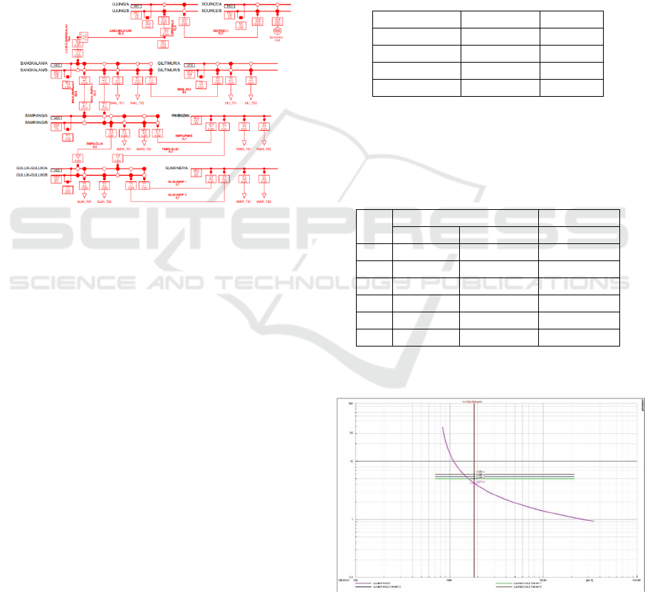
The following in Figure 4 below shows the voltage
graph data on each bus
:
Figure 4: Ujung-Bangkalan OLS and OCR Coordination
Curve.
ICATECH 2023 - International Conference on Advanced Engineering and Technology
212

Description
: Current
: OCR
: OLS Stage 3
: OLS Stage 2
: OLS Stage 1
X-Axis : Current Values
Y-Axis : Relay Working Time
Table 3: OCR and OLS Relay Performance Data.
Working
Current
686,05 744,9 744,9 744,9 1826,97
OCR
T(s)
Calc ~ ~ ~ ~ 4,193
Sim 10000
9999,9 9999,9 9999,9
4,217
OLS
T(s)
Std ~ 5 5,5 6 -
Sim 10000 5 5,5 6 -
OLS
- T1 T2 T3
Condition 0 1 2 3 4
Description
T1 : PMT 20 KV Trafo 2 GI Bangkalan
T2 : PMT 20 KV Trafo 2 GI Sampang, PMT 20
KV Trafo 2 GI Sumenep
T3 : PMT 20 KV Trafo 1 GI Bangkalan,
PMT 20 KV Trafo 1 GI Sampang,
PMT 20 KV Trafo 1 GI Sumenep
0 : Normal
1 : OLS Stage 1
2 : OLS Stage 2
3 : OLS Stage 3
4 : OLS Not Working
The effect of OLS work on the load on Madura Island
is to prevent widespread blackouts due to overloading
by extinguishing some of the load using OLS. The
load that was extinguished based on the data of the
UP2B defense scheme, namely
• At Stage 1, turn off the load. The target of OLS
phase 1 is PMT 20 kV Incoming Transformer-2
150/20 kV GI Bangkalan. The total load that was
extinguished was 18.4 MW.
• Turn off the load at Stage 2. The target of OLS
phase 2 is PMT 20 kV Incoming Transformer-2
150/20 kV GI Sampang and PMT 20 kV Incoming
Transformer-2 150/20 kV GI Sumenep. The total
load that was extinguished was 78 MW.
• Turn off the load at Stage 3. The targets of OLS
phase 3 are PMT 20 kV Incoming Transformer-1
150/20 kV GI Bangkalan, PMT 20 kV Incoming
Transformer-1 150/20 kV GI Sampang, and PMT
20 kV Incoming Transformer-1 150/20 kV GI
Sumenep. The total load that was extinguished
was 81.9 MW.
Table 4: OLS SUTT 150 kV Load Shedding Ujung-
Bangkalan.
Tahap Total Beban (MW)
1 18,4
278
3 81,9
5 CONCLUSION
Based on the results of the analysis and simulation in
this thesis research, it can be concluded:
1. The operation of OCR and OLS relays in terms of
calculations and simulations is in accordance with
the standard calculation provisions regulated by
PLN.
2. The coordination of OLS and OCR relays in
securing the distribution system has gone well,
where OLS works first to secure overload by
using 3 stages. The OLS setting is smaller than the
OCR setting in order to prevent OCR from
working before OLS. OLS stages are
distinguished based on the working time. OLS
works within 5 DT for the first stage, 5.5 DT for
the second stage, and 6 DT for the third stage. And
for OCR working time using standard inverse
characteristics, namely working time based on the
value of the current flowing, the greater the value
of the current flowing, the faster the relay works.
3. OLS works according to the calculation of the
setting value, which is 710 A, but when OLS fails
to reduce the overload, the OCR relay will work,
where the current OCR working setting at Bay
Bangkalan GIS Ujung is 760 A.
OLS has an effect on reducing excessive loads,
namely by extinguishing the load according to the
OLS target to prevent widespread blackouts.
REFERENCES
A. A. S. P. Larekeng, & M. Iqbal. (2020). Analisis kinerja
over current relay (ocr) & ground fault relay (gfr) pada
sistem 20 kv ultg maros menggunanakan alat uji cmc
356.
Anung, & Achirul Ramadhani. (2017). Penerapan ols untuk
meminimalisir pemadaman meluas akibat overload
pada satu penghantar. Jurnal Isu Teknologi, 12(1).
A.W Hidayat. (2013). Analisa Setting Rele Arus Lebih dan
Rele Gangguan Tanah pada Penyulang Topan Gardu
Induk Teluk Betung. Jurnal Rekayasa Dan Teknologi
Elektro, 7(5), 5–28.
E. Pafela, & E. Hamdani. (2016). Studi Penyetelan Relay
Arus Lebih (OCR) Pada Gardu Induk Teluk Lembu
Defence Scheme on Madura Island Against System Loading Variation for Energy Security
213

Pekanbaru. J. Online Mhs. Fak. Tek. Univ. Riau, 4(1),
1–17.
I. Hajar, & M. Ridho. (2020). Review dan Resetting Skema
Overload Shadding Interbus Transformer Energi dan
Kelistrikan. 12(1).
PT. PLN (Persero). (2010). SPLN T5.002-1:2010 Standar
Pola Proteksi.
SPLN T5.002-1:2010 Standar Pola Proteksi. (2010).
T. Nova. (2013). Perhitungan Setting Rele OCR dan GFR
pada Sistem Interkoneksi Diesel Generator di
Perusahaan. 1(1), 76–85.
U. Induk, P. Pengatur, U. Pengatur, & B. Jawa. (2020).
Defense Scheme Sistem Jawa Timur.
.
ICATECH 2023 - International Conference on Advanced Engineering and Technology
214
