
Joint Stiffness Adjustment of a Pneumatic Driven Exoskeleton
Pavel Venev
a
, Dimitar Chakarov
b
and Ivanka Veneva
c
Institute of Mechanics, Bulgarian Academy of Sciences, “Acad. G. Bonchev” str., Block 4, Sofia 1113, Bulgaria
Keywords: Exoskeleton, Upper Limb, Transparency, Pneumatic, Cylinders, Stiffness, Torque, Air Pressure,
Closed Chambers, Gravity Compensation.
Abstract: The work studies an exoskeleton on the upper limb intended for rehabilitation and training. To meet the
requirements of rehabilitation exoskeletons for transparency on the one hand and efficiency on the other, a
pneumatic actuation with a wide range of control pressure is offered. The subject of the work is the
development of a pneumatic drive that allows simultaneous adjustment of stiffness and torque in the joints of
the exoskeleton. For this purpose, pressure in the cylinder chambers both higher and lower than atmospheric
is used. The work presents the structure of the exoskeleton and a model of pneumatic actuation in the joints
of the exoskeleton. Equations are derived for the torque and joint stiffness resulting from the elasticity of the
air in the closed chambers of the pneumatic cylinders. The work proposes one approach to adjust the stiffness
at certain joint position. In this position, the joint torque is varied by creating pressure profiles in the two
chambers, so the joint stiffness is adjusted in addition to the joint torque. The change in joint torque due to
elastic deviations from the set position is also evaluated. An example of compensating gravity loads and
providing transparency through pneumatic actuation is shown.
1 INTRODUCTION
An alternative to conventional manual therapy for
improving motor function in post-stroke patients is
the use of robotic exoskeletons for rehabilitation
(Manna, 2018). The rehabilitation exoskeleton must
be able to create a large force to support, assist and
guide the patient's arm in the early stages of recovery,
as well as to follow the human arm without resistance
by responding to the movements performed by the
patient in the full recovery stage (Jarrasse, 2014).
Therefore, in the control of rehabilitation
exoskeletons, two ideal modes can be defined that
encompass all therapeutic interventions: 'robot in
charge' and 'patient in charge' (Veneman, 2006). In
the "robot in charge" mode, it is important that the
robot has sufficient force and power to realize the
desired motion with relatively high impedance. In the
“patient in charge” mode, it is important that the
interaction forces between the exoskeleton and the
human are low, in other words, the perceived
a
https://orcid.org/0000-0001-7809-3540
b
https://orcid.org/0000-0002-2312-5725
c
https://orcid.org/0000-0001-5501-7668
impedance of the patient must be low. The key feature
here is transparency.
In order to provide safety and transparency to the
interaction, there are two main approaches to change
the mechanical impedance of the structure: active and
passive. Electric motors and other active actuators are
used to control the impedance of rehabilitation
exoskeletons through an active approach. Active
impedance control is based on the use of sensors and
feedback. Impedance control successfully manages
patient-exoskeleton interaction in all modes of
therapeutic interventions (Courtois G., 2021).
The passive approach involves a natural and
inherently safe actuator. Pneumatic actuation has a
natural compliance and allows to achieve inherent
safety and transparency in the rehabilitation process
in a passive manner (Morales, 2011). Pneumatic
actuation also allows impedance control via the active
approach. There are different types of pneumatic
actuators. The best known are conventional
pneumatic cylinders and rotary pneumatic motors. On
the one hand, they are characterized by large size,
Venev, P., Chakarov, D. and Veneva, I.
Joint Stiffness Adjustment of a Pneumatic Driven Exoskeleton.
DOI: 10.5220/0012119200003546
In Proceedings of the 13th International Conference on Simulation and Modeling Methodologies, Technologies and Applications (SIMULTECH 2023), pages 361-368
ISBN: 978-989-758-668-2; ISSN: 2184-2841
Copyright
c
2023 by SCITEPRESS – Science and Technology Publications, Lda. Under CC license (CC BY-NC-ND 4.0)
361
high weight and rigidity of construction, but on the
other hand, when mounted in the fixed base, they
provide the advantages of pneumatic actuation.
Pneumatic actuators are usually operated at
pressures higher than atmospheric pressure. Recently,
some soft pneumatic actuators that are activated by
vacuum have been developed (Yang D., 2017). Using
the effect of mechanical deformation to generate
controlled force, vacuum-actuated mechanisms have
been successfully developed and used for soft robotic
systems (Matthew A., 2017). Vacuum actuators have
many advantages over positive pressure actuators.
For example, this type of actuator offers implicitly
safe operation as the actuation force is limited by the
magnitude of atmospheric pressure (Tawk Ch., 2019),
also this leads to improved actuator life and
durability.
An upper limb pneumatic powered exoskeleton
has been developed for training and rehabilitation
assisted by interactions in virtual scenes (Chakarov
D., 2019). A study was conducted where the
exoskeleton driven by pneumatic cylinders with
positive pressure was compared with the case where
the exoskeleton was driven by pneumatic cylinders
with vacuum pressure (Chakarov D., 2022). This
study shows that vacuum pressure drive reduces
stiffness and results in high transparency and patient
safety. However, low stiffness is associated with poor
force response and low efficiency when performing
"robot-in-charge" operations. The combination of
transparency requirements on the one hand and
efficiency requirements on the other can be achieved
by pneumatic actuators with a wide range of control
pressures.
The subject of this work is the development and
investigation of a pneumatic actuation for the
exoskeleton that allows simultaneous adjustment of
stiffness and torque in the joints of the exoskeleton.
The goal of the work is to create an approach to adjust
the stiffness of the joint and the torque in the joint by
driving the pressures in the chambers both higher and
lower than atmospheric pressure.
2 STRUCTURE AND MODEL OF
PNEUMATIC ACTUATION IN
EXOSKELETON JOINTS
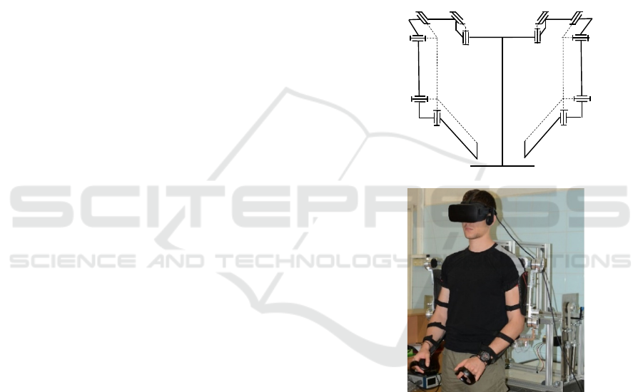
A prototype of a lightweight upper limb exoskeleton
has been developed by the authors (Chakarov D.,
2022). The mechanical structure of the exoskeleton
consists of two arms. Each arm includes pairs of
identical rotational joints for the movements of the
clavicle J1, J2, shoulder J3, J4 and elbow J5, J6, as
shown in Figure 1a), b). The joints have the following
range of movement: J1(15°), J2 (15°), J3(120°), J4
(120 °), J5 (150 °), J6 (135 °). Each arm has a total of
6 degrees of mobility, mimicking the natural
movement of the human arm from back to elbow.
Each arm of the exoskeleton has six movable
segments (1, 2, 3, 4, 5 and 6) made primarily of
aluminium alloy. Plastic shells with straps are placed
on the segments for attachment to the human limb
(Figure 1b). This structure was chosen for designing
the arm exoskeleton using uniform universal joints
and thus avoid more complex solutions involving
circular guide and triaxial joints.
a)
J3
J4
J5
J6
EE
4
3
5
6
J2
J1
2
1
0
R
L
J1
J2 J3
J4
J5
J6
1
3
4
5
6
EE
b)
Figure 1: Exoskeleton of the upper limbs: a) structural
scheme; b) prototype.
For each joint of the exoskeleton, a drive unit
including pneumatic cylinders and cable
transmissions was created. The drive unit of each
joint is built as a separate device located in the fixed
base. A scheme of the drive unit is shown in Figure 2.
The base has a bearing wheel 1 with a cable reel R1
mounted on it. Bowden cables T1, T2 are used to
connect the reel R1 and a similar reel located in the
exoskeleton joint. The radius of reel R
1
is r = 0.032
m.
SIMULTECH 2023 - 13th International Conference on Simulation and Modeling Methodologies, Technologies and Applications
362
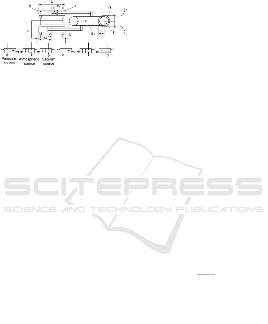
Figure 2: Scheme of the pneumatic drive of exoskeleton
joints.
The pneumatic drive unit includes a pair of
pneumatic cylinders C1, C2 mounted in the base and
a belt transmission as shown in Figure 2. Pneumatic
cylinders with a diameter of D = 0,032 m are used.
The areas on either side of the cylinder piston are s
1
=
804 10
-6
m and s
2
= 725 10
-6
m. The transmission
includes a timing belt B
1
and an additional wheel 2
for transmitting the motion from the pneumatic
cylinders to the wheel 1. The cylinders
simultaneously drive opposite sides of the belt B1.
The left chamber of one cylinder is connected to the
right chamber of the other cylinder by piping, and the
other right and left chambers are connected by
another piping (Figure 2). The piping of each pair is
connected to three parallel valves, one of which
supplies pressurized air to the chambers, the other
connects the chambers to vacuum pressure, and the
third connects the chambers to atmospheric pressure.
Pressure sensors are installed on each line.
The work evaluates the interaction between the
patient and the exoskeleton in so-called "patient in
charge" modes. In this mode, the exoskeleton does
not generate active forces. The resisting forces are
determined only by the mechanical impedance of the
exoskeleton. The resisting force applied to the
operator's hand is determined by the inertial,
frictional and gravitational forces as well as the
elastic forces of the pneumatic actuator.
The joint torque Q
h
of the resistive force applied
to the operator's arm to overcome the mechanical
impedance of the exoskeleton is determined
according to equation:
pgfr
J
h
QQQQQ +++=
(1)
Above: Q
J
presents the torque created by the
motor and the transmissions inertia as well as the
exoskeleton inertia; Q
fr
represents the friction torque
which is mainly the result of the friction forces
generated in pneumatic actuators and Bowden cables;
Q
g
is the torque created by the exoskeleton gravity;
Q
p
is a difference of torques Q
pa
and Q
pb
produced
by the forces in the two pneumatic cylinders,
represented by the equality
pbpap
QQQ −=
(2)
If one of the chambers of the pneumatic cylinders
closes, it generates an elastic force caused by the
change in the volume of the enclosed air. The
variation of the chamber volume is calculated from
the initial piston position X
0
as presented in Figure 2.
Assuming that air is an ideal gas undergoing an
isothermal process (Czmerk, A., 2017), the rate of
change of pressure p and the change of volume V in
the closed chamber of the cylinder can be expressed
by the equation of the polytrophic process
CVp =
(3)
where C is a constant.
Once in the initial position of the cylinders X
0
(Figure 2), the chamber a of the pneumatic cylinders
is closed with a pressure p
0
a
and the volume V
(a)
of the
chamber is represented as a function of the piston area
and chamber length, equation (3) takes the form:
a210
0
a
C)ss(Xp =+
(4)
where s
1
and s
2
are the areas on either sides of the
piston and C
a
is a constant.
After the arm movements are performed, the
piston makes a deviation x from the initial position X
0
(Figure 2) and the pressure p
a
in the closed chamber
changes. After that, equation (3) should take a new
form:
a210a
C)ss)(xX(p =+−
(5)
The above equations give the equality for the pressure
change p
a
as a function of piston deflection x
xX
Xp
p
0
0
0
a
a
−
=
(6)
The torque of the elastic force in chamber a at
deviation of the pistons x from the initial position X
0
is obtained by the equation
)rs(s
xX
Xp
Q
21
0
0
0
a
pa
+
−
=
(7)
where r is the radius of reel R
1
of Figure 2.
In the same way, when in the initial position of the
cylinders X
0
, chamber b is closed with pressure p
0
b
and the piston makes a deviation x from the initial
Joint Stiffness Adjustment of a Pneumatic Driven Exoskeleton
363

position X
0
, (Figure 2), equation (3) allows to draw up
the following equalities
b210
b
210
0
b
C)ss)(xXL(p
)ss)(XL(p
=++−=
=+−
(8)
xX-L
)X-(Lp
p
0
0
0
b
b
+
=
(9)
where L is the cylinder length and C
b
is a constant.
The equation for the torque of the elastic actuator
due to the displacement of the pistons x from the
initial position X
0
in chamber b is obtained in a similar
way
)rs(s
xX-L
)X-(Lp
Q
21
0
0
0
b
pb
+
+
=
(10)
If either of the chambers a or b of the cylinders
is open to the atmosphere, the air in it does not change
its pressure and volume, so that the moments
generated by the pneumatic forces in the chambers
are constant as defined by the equations
r)s(spQ
21atmpa
+=
(11)
r)s(spQ
21atmpb
+=
(12)
In equations (5) - (10) piston deviation x is
determined by the deviation q at the joint angle and
the radius r of the wheel R
1
as follows
q
r
x
=
(13)
The behavior of closed pneumatic cylinders
according to (7) and (10) behaves like a variable
compliance spring. The stiffness of the joint driven by
pneumatic cylinders can be determined as a derivative
of the joint torque (2) about the joint deviation,
according to the equality:
b
a
pbpap
KK
q
x
x
Q
q
x
x
Q
q
Q
K −=
∂
∂
∂
∂
−
∂
∂
∂
∂
=
∂
∂
=
(14)
After differentiation of equations (7) and (10),
taking into account (13), the equations for the joint
stiffness as a result of the elasticity of the air in
chambers a and b are obtained as follows
2
21
2
0
0
0
a
a
)rs(s
)x(X
Xp
K +
−
−=
(15)
2
21
2
0
0
0
b
b
)rs(s
)xX-(L
)X-(Lp
K +
+
−=
(16)
If one of the chambers is open to the atmosphere,
according to (11) (12) and (14) it follows that
Q
p(a,b)
=const. and the joint stiffness in chambers a and
b is
0K
a
=
(17)
0K
b
=
(18)
3 JOINT STIFFNESS
ADJUSTMENT
In this work, the possibility of adjusting the stiffness
in a certain joint position is investigated. In this
position, the joint torque changes linearly for 10
values, from zero at the first point to one positive
value at the last point. For each point, the pressures in
the two chambers are changed so that the joint
stiffness is adjusted in addition to the joint moment.
The joint moment and joint stiffness are evaluated at
the piston initial location corresponding to the certain
joint position when the deviations from this location
are zero (x=0). The length of the cylinder and the
initial location of the piston are selected respectively
L=0.125 m and X
0
=0.0625 m (Figure 2). According
to (2), (7), (10), the pressure in the chambers is
changed linearly to obtain a linear moment variation.
Three pressure variation profiles are proposed: A.
Generation of minimum stiffness by vacuum
pressure; B. Variable stiffness generation with
vacuum pressure and chamber opening; C.
Generation of high stiffness by pressures higher than
atmospheric pressure.
A. Generation of minimum stiffness by
vacuum pressure.
Vacuum pressure in chamber b of the cylinders
is used to generate low stiffness values. Chamber a in
this phase is open to the atmosphere p
a
=p
atm
. Figure 3
shows the pressure variation in chamber a and in
chamber b at which the joint moment Q
p
increases
linearly. In the first phase, the pressure in chamber b
drops smoothly from p
b
=100 kPa and reaches full
vacuum p
b
=0, and chamber a is open p
a
=p
atm
, and
generates no stiffness. The joint stiffness is
determined by relation (14, 16 and 17) for x=0 and
the joint moment is determined by relations (2), (10)
and (11) for x=0.
SIMULTECH 2023 - 13th International Conference on Simulation and Modeling Methodologies, Technologies and Applications
364

In the second phase, chamber a closes and the
pressure in it increases smoothly, while the pressure
in chamber b is kept p
b
=0. In this case both chambers
are closed, the joint stiffness is determined by
equations (14), (15) and (16) for x=0 and the joint
moment is determined by equations (2), (7) and (10)
for x=0.
Figure 3: Profile A of pressure variation in chambers a and
b of the pneumatic cylinders.
Figure 6 shows the variation of joint moment from
0 to 11. 3 Nm as well as the variation of joint stiffness
at the ten pressure points. The joint stiffness is
minimum in the case when one chamber has full
vacuum p
b
=0 and the other chamber is open to the
atmosphere. The moment in this position is
determined by the atmospheric pressure p
a
=100 kPa.
Further the moment increases as chamber a is closed
with higher pressures p
a
>100 kPa, at which the
stiffness also increases.
B. Variable stiffness generation with vacuum
pressure and chamber opening.
Here, a vacuum pressure profile is proposed as a
modification of profile A, in which the stiffness is
increased by opening the vacuum chamber and using
atmospheric pressure.
Figure 4 shows the pressure variation in chamber
a and chamber b at which the joint moment Q
p
increases linearly. In the first phase, the pressure in
chamber b drops smoothly from atmospheric pressure
p
b
=100 kPa to full vacuum p
b
=0, and chamber a is
closed in this phase with atmospheric pressure p
a
=100
kPa. Since both chambers are closed the joint stiffness
is determined by the relation (14), (15) (16) for x=0
and the joint moment is determined by equations (2),
(7) and (10) for x=0.
In the second phase, chamber b is open to the
atmosphere, (p
b
= p
atm
)
and in chamber a, the pressure
increases by such values that the moment in the joint
increases linearly. In this case, chamber a is closed
and chamber b is open and the joint stiffness is
determined by relationships (14), (15) and (18). The
moment in the joint is determined by (2), (7) and (12).
The piston deviations are zero (x=0).
Figure 4: Profile B of pressure variation in chambers a and
b of the pneumatic cylinders.
Figure 6 shows the variation of joint moment (2)
as well as the variation of joint stiffness (14). The
joint stiffness changes in a similar way as in profile
A, but at higher values. In contrast to the previous
case, the increase in stiffness is achieved by chamber
a being closed at a pressure equal to atmospheric in
the first phase, and chamber b being opened to
atmosphere in the second phase. Switching between
the two stiffness values is easily achieved by closing
and opening to atmosphere the chambers of the
cylinders.
C. Generation of high stiffness by pressures
higher than atmospheric pressure.
To generate high stiffness, different profiles can
be created at pressures higher than atmospheric
pressure and the chambers closed. Thus, it is possible
to achieve the desired joint moment and high
stiffness. Figure 5 shows a variation of pressures in
chamber a and chamber b in which the joint moment
(2) increases linearly and the pressure profile is
similar to that of cases A and B, but at higher values.
In the first phase, chamber a is closed with pressure
p
a
=200 kPa, and the pressure in chamber b drops
smoothly from p
b
=200 kPa to p
b
=p
atm
. Since both
chambers are closed, the moment is determined by
(2),(7), and(10) and the joint stiffness is determined
by the relation (14),(15), and (16). The piston
deviations are zero (x=0).
In the second phase, chamber b is closed with
pressure p
b
=200 kPa , and the pressure in chamber a
increases by such values that the moment in the joint
increases linearly. Here both chambers are closed, the
joint moment and joint stiffness are determined by the
same relationships.
0
100
200
300
400
01234567891011
pa[kPa]
point No
pb[kPa]
pb pa
0
50
100
150
200
250
300
350
400
01234567891011
pa[ kPa]
pb[kPa]
point No
pb pa
Joint Stiffness Adjustment of a Pneumatic Driven Exoskeleton
365
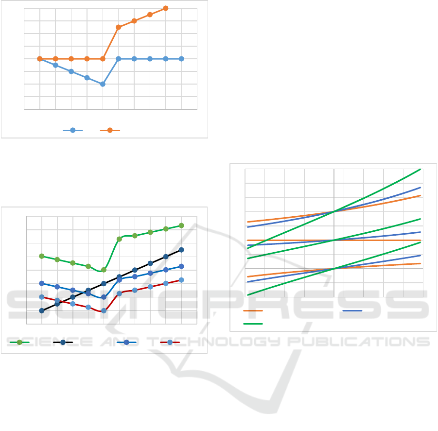
Figure 5: Profile C of pressure variation in chambers a and
b of the pneumatic cylinders.
Figure 6 shows the variation of joint moment (2)
as well as the variation of joint stiffness (14).
Figure 6: Variation in joint torque and joint stiffness for the
three pressure profiles A, B and C.
The joint stiffness profile is similar to the previous
cases, but the stiffness values are higher. Of course it
is possible to generate stiffness with other
modification profiles. A characteristic of the
proposed profiles A, B and C is that a minimum
stiffness is generated not at zero value but at an
average value of the joint moment (5Nm for the
considered case). It can be equal to an average value
of the joint moment created by static loads on the
exoskeleton for the position under consideration.
Transparency in this position will be maximized. At
any other time in the joint, the stiffness will be higher.
4 JOINT TORQUE ASSESSMENT
When the patient deviates the exoskeleton from the
initial position in which any of the cylinder chambers
is closed, resistive forces arise as a result of the
elasticity of the closed gas. When both chambers are
closed the moment from the elastic forces is
determined from equations (2), (7) and (10) as a
function of the deviation from the initial position x.
For a deviation x = [-0.014; 0.014] m which
corresponds according to (13) to a deviation in the
joint angle q = [-0. 436;0. 436] rad, the variation of
the joint moment is shown on Figure 7. The figure
shows the variation of the moment in the joint from
initial values of 0, 5 and 10 Nm (points 1, 5 and 9 in
the graph of Figure 6) at three stiffness values
corresponding to the three pressure profiles A, B and
C in the graph of Figure 6. Profile A shows the
smallest moment variations at all three points.
Figure 7: Variation of the joint torque Qp from initial values
of 0, 5 and 10 Nm, corresponding to the three pressure
profiles A, B and C.
In the "patient in charge" mode, when the patient
performs independent movements, the exoskeleton
should provide transparency. For this purpose, the
resistive forces due to the mechanical impedance of
the exoskeleton must be compensated. In low
dynamic mode, only resistance of gravity and
stiffness can be taken into account. Then torque (1) of
forces applied to the patient's hand is sum of moments
of gravity forces and compensatory forces of the
pneumatic drive
pgh
QQQ +=
(19)
In order to achieve transparency, compensatory
forces with minimum stiffness must be generated. To
compensate for gravity loads, it is appropriate to use
the moment from the pneumatic drive achieved at
pressures generating the lowest stiffness. Thus, with
profile A (Figure 6), the lowest stiffness value is
achieved at 5 Nm. Figure 8 shows the variation of the
moment from the pneumatic drive at an initial value
0
50
100
150
200
250
300
350
400
01234567891011
pa[kPa]
pb[kPa]
point No
pb pa
-2,5
0,0
2,5
5,0
7,5
10,0
12,5
15,0
17,5
01234567891011
K
[Nm/rad
point No
Qp [Nm]
K (C) Qp (A,B,C) K (B) K (A)
-5,0
-2,5
0,0
2,5
5,0
7,5
10,0
12,5
15,0
17,5
-0,45 -0,35 -0,25 -0,15 -0,05 0,05 0,15 0,25 0,35 0,45
Qp [Nm
]
q [rad]
Pressure profile A Pressure profile B
Pressure profile C
SIMULTECH 2023 - 13th International Conference on Simulation and Modeling Methodologies, Technologies and Applications
366

of 5 Nm and the pressures in the chambers
corresponding to profile A. The figure shows the
variation of the gravitational moment in the position
of the joint with deviations q = [0.436;0.436] rad. The
resultant moment at the joint according to (19) is also
shown in the graph. With small deviations, it
oscillates around a zero value, ensuring transparency
of the interaction with the patient. Compensating for
larger or smaller gravity moments with this pressure
profile also results in low resistive forces.
In the 'robot in charge' mode, when the
exoskeleton has to implement not only compensation
but also the desired movement, it is appropriate to
apply a pressure profile similar to the proposed
profile C. Figure 9 shows a case when with a torque
in the joint of 5 Nm and pressure profile C, the same
gravity loads are compensated. Transparency here is
lower. Deviations from the set position lead to
resistance with significant torque deviations.
Figure 8: Joint torques deviations after gravity
compensation with pressures in the chambers
corresponding to profile A.
Figure 9: Joint torques deviations after gravity
compensation with pressures in the chambers
corresponding to profile: C.
5 CONCLUSIONS
The work studies an exoskeleton on the upper limb
intended for rehabilitation and training. A pneumatic
drive with a wide range of control pressure is
available to meet the requirements of rehabilitation
exoskeletons for transparency on the one hand and
efficiency on the other. Cylinder chamber pressures
both higher and lower than atmospheric are used. The
development of a pneumatic drive that allows
simultaneous adjustment of stiffness and torque in the
joints of the exoskeleton is included in the work. The
work presents the structure of the exoskeleton and a
model of pneumatic actuation in the joints of the
exoskeleton. Equations are derived for the torque and
joint stiffness resulting from the elasticity of the air in
the closed chambers of the pneumatic cylinders. In
the work, an approach for adjusting the stiffness at a
certain position of the joint is proposed. In this
position, the joint torque is varied by creating
pressure profiles in the two chambers, so that the joint
stiffness is adjusted in addition to the joint torque. A
characteristic of the proposed profiles is that the
minimum stiffness is generated not at zero value, but
at an average value of the joint torque. To compensate
the gravity loads by the pneumatic drive in a certain
position, it is appropriate to use the moment
corresponding to the lowest stiffness. Then
transparency in this position will be best. An example
of compensation for gravity when providing
transparency through pneumatic activation is shown
in the work.
ACKNOWLEDGEMENTS
This research was supported by the Operational
Program "Science and education for smart growth"
through the project “MIRACle”, № BG05M2OP001-
1.002-0011 to which the authors would like to express
their deepest gratitude.
REFERENCES
Manna S. K., Dubey V. N., (2018). Comparative study of
actuation systems for portable upper limb exoskeletons,
Medical Engineering and Physics, 60, 1–13.
Jarrasse, N., T. Proietti, et al., (2014). Robotic
Exoskeletons: A Perspective for the Rehabilitation of
Arm Coordination in Stroke Patients, Frontiers in
Human Neuroscience, Vol.8, Art.947, 1-13.
Veneman, J.F., R. Ekkelenkamp, et al., (2006). A series
elastic- and bowden-cable-based actuation for use as
torque actuator in exoskeleton-type robots, The Int.
Journ. of Rob. Research, vol. 25(3), 261-281.
Courtois G., Chevrie J., Dequidt A., Bonnet X. and Pudlo
P. (2021). Design of a Rehabilitation Exoskeleton with
Impedance Control: First Experiments. Proc.of the
-10
-5
0
5
10
-0,45 -0,30 -0,15 0,00 0,15 0,30 0,45
q[rad]
[Nm]
Qp Qh Qg
-10
-5
0
5
10
-0,45 -0,30 -0,15 0,00 0,15 0,30 0,45
q[rad]
[Nm]
Qp Qh Qg
Joint Stiffness Adjustment of a Pneumatic Driven Exoskeleton
367

18th Int. Conf. on Informatics in Control, Automation
and Robotics – ICINCO 2021, 469-476.
Morales R., et al., (2011). Pneumatic robotic systems for
upper limb rehabilitation, Med. Biol. Eng. Comput. 49,
1145–1156.
Yang D., M. S. Verma, E. Lossner, D. Stothers, G. M.
Whitesides, (2017). Negative-pressure soft linear
actuator with a mechanical advantage. Adv. Mater.
Technol., vol.2, issue 1, 1600164, 1-6.
Matthew A., Robertson and Jamie Paik, (2017). New soft
robots really suck: Vacuum-powered systems empower
diverse capabilities. Science Robotics, vol. 2, Issue 9,
doi: 10.1126/scirobotics.aan6357, 1-27.
Tawk, C., Spinks, G. M., in het Panhuis, M. & Alici, G.
(2019). 3D Printable Linear Soft Vacuum Actuators:
Their Modeling, Performance Quantification and
Application in Soft Robotic Systems. IEEE/ASME
Transactions on Mechatronics, 24 (5), 2118-2129.
Chakarov D., Veneva I., Tsveov M., Mitrouchev P., Venev
P. (2019), Design of a Two Arms Exoskeleton as Haptic
Device for Virtual Reality Applications, Lecture Notes
in Mech. Eng., Springer Nature, Chapter 25, 252-262.
Chakarov, D., Veneva, I., Venev, P. (2022). Comparative
Study of a Vacuum Powered Upper Limb Exoskeleton,
Pros. of the 19 th Int. Conf. on Informatics in Control,
Automation and Robotics, ICINCO 2022, 403-410.
Czmerk, A., A. Bojtos, (2017). Stiffness investigation of
pneumatic cylinders, 59th Ilmenau Scientific
Colloquium, Technische Universität Ilmenau, 11 – 15
September, 2017, URN: urn:nbn:de:gbv:ilm1-
2017iwk-148:6, 1-7.
SIMULTECH 2023 - 13th International Conference on Simulation and Modeling Methodologies, Technologies and Applications
368
