
Modeling & SMC Based Trajectory Tracking for a Tilt-Rotor
Convertible UAV
Mohamed Zakaria Mimouni, Oualid Araar, Abdelkader Ouadda and Moussa Haddad
Ecole Militaire Polytechnique, Algeria
Keywords:
Tilt-Rotor UAV, SMC Control, Convertible UAV, Trajectory Tracking.
Abstract:
Convertible UAVs combine the vertical takeoff and landing (VTOL) capabilities of multi-rotors with the en-
durance and high speed of fixed-wing drones. This work is concerned with a particular category of convertible
UAVs, commonly termed Tilt-rotor UAVs (TRUAVs). First, a detailed dynamic model for a Quad-TRUAV is
developed. This model features strong non-linearities and coupling, making its control a challenging task. The
second contribution of this work is the design of a sliding mode controller (SMC) to ensure trajectory track-
ing. Simulations conducted on the full non-linear model of the famous Zagi-wing UAV show very promising
results.
1 INTRODUCTION
Unmanned aerial vehicles (UAVs) have a wide range
of military and civilian applications. These include
infrastructure inspection, search and rescue, data col-
lection (Li et al., 2021) delivery services, agriculture
(Kim et al., 2019) and surveillance, to name but a few
(Shakhatreh et al., 2019).
Convertible or Hybrid UAVs is a particular class,
which has attracted considerable attention during the
last few years. Hybrid designs target to combine the
advantages of VTOL UAVs and those of the fixed
wing category. These include high payload capacity,
great operational range, high cruise speed, in addition
to the stationary flight and VTOL capabilities.
Depending on their switching mechanism, con-
vertible UAVs can be categorised into three main
categories. The first includes tilt-rotors, which tilt
their rotors to switch between VTOL and cruise flight
modes. The second is tilt-wing in which the drone tilts
both rotors and wings for switching. In the third cat-
egory, named tail-sitters or tilt-bodies, the entire air-
frame is tilted for transitioning between flight modes.
The Tiltrotor UAV (TRUAV) is a very popular
class of hybrid UAVs, in which the mounted rotors
gradually tilt in the direction of flight, driving the
aircraft forward until steady flight is reached (Saeed
et al., 2015) (Hegde et al., 2019). This class is char-
acterized by a simple transition manoeuvre and good
controllability and stability (Saeed et al., 2018).
The TRUAV considered in this work is actuated
using only propellers, i.e it contains no control sur-
faces. In such a category, the tilting of the rotors re-
sults in considerable changes in the drone’s center of
gravity and moment of inertia (Su et al., 2019). It also
results in rapid variations in the aerodynamic forces
acting on the vehicle while changing from hover to
cruise flight (Phung and Morin, 2014). These chal-
lenges complicate the dynamic model of the drone
and hence its control (Ducard and Allenspach, 2021).
Among research works which have dealt with the
control of TRUAVs, Papachristos et al. (Papachristos
et al., 2013) developed a linear quadratic (LQ) control
scheme for position control of a Three-Rotor TRUAV.
In the hover phase, they implemented and experimen-
tally tested PD & double Derivative controller (Pa-
pachristos et al., 2012).
In order to stabilize the pitch angle of a Three-
Rotor TRUAV, Ta et al. (Ta et al., 2012) combined
a linear PID controller and a nonlinear saturated sig-
moid function. For the position, the authors employed
a neural network-based adaptive controller. The pro-
posed controller, however, does not account for the
cross-coupling between states.
Flores et al. (Flores et al., 2012) applied a non-
linear backstepping controller for cruise flight. In
hover mode, the TRUAV was controlled as a conven-
tional multirotor using a feedback linearization tech-
nique.
In another work (Flores and Lozano, 2013), Flo-
res et al. proposed a control solution to deal with the
transition phase. The desired altitude was maintained
Mimouni, M., Araar, O., Ouadda, A. and Haddad, M.
Modeling SMC Based Trajectory Tracking for a Tilt-Rotor Convertible UAV.
DOI: 10.5220/0012121700003546
In Proceedings of the 13th International Conference on Simulation and Modeling Methodologies, Technologies and Applications (SIMULTECH 2023), pages 97-103
ISBN: 978-989-758-668-2; ISSN: 2184-2841
Copyright
c
2023 by SCITEPRESS – Science and Technology Publications, Lda. Under CC license (CC BY-NC-ND 4.0)
97

𝑻
𝟐
𝑻
𝟏
𝜸
𝟏
𝜸
𝟏
𝑻
𝟒
𝑻
𝟑
𝜸
𝟐
=
ൗ
𝝅
𝟐
𝜸
𝟐
𝒙
𝒛
𝒚
Figure 1: Illustration of the Quad-TRUAV considered in
this work.
using nested saturation control. The input control vec-
tor includes elevator deflection, tilt angle, total rotor
thrust, and difference in thrust between the front and
rear rotors.
Hernandez-Garcia et al.(Hernandez-Garcia and
Rodriguez-Cortes, 2015) applied a gain scheduling
controller to a dual TRUAV. Based on the Jacobian
linearisation of the model of the drone, a set of linear
controllers was designed for takeoff, vertical, hover-
ing, and horizontal flight conditions.
Govdeli et al. (Govdeli et al., 2019) presented a
Quad-Tilt-Rotor with two configurations. The authors
used a PID controller to generate the control inputs for
the longitudinal plan. The parameters of the forward
transition controller were different from those of the
backward transition controller. The control scheme
did not guarantee to maintain the altitude during the
transition.
Chen et al. (Chen et al., 2021) designed Cascaded
controller for a Three-Rotor TRUAV. During the tran-
sition, the drone was controlled by mixing control sur-
faces and rotors depending on the airspeed. A sliding
mode controller was used for all channels.
To the best of the author’s knowledge, all previous
works employ two controllers for each flight phase. In
this paper, a control architecture employing a single
controller for both VTOL and cruise flight phases is
considered. A sliding mode controller (SMC) is then
derived to ensure trajectory tracking. The proposed
solution is validated on the full nonlinear model of
the famous Zagi wing drone.
The remainder of this paper is organised into four
sections. Section II presents the development of the
TRUAV’s kinematic and dynamic model. The control
architecture and associated sliding mode controller
are discussed in section III. Obtained results are pre-
sented and analysed in section IV.
2 DYNAMIC MODELING OF THE
Quad-TRUAV
The dynamic model of the Quad-TRUAV is derived
based on the Newton-Euler formalism
m
˙
V
g
E
= R
E
B
F
B
IΩ + Ω× IΩ = M
B
(1)
Using the blade element theory, the thrust and re-
active torque generated by a rotor are modelled as
(Prouty, 2002)
T
i
= K
l
· ω
2
i
C
i
= K
c
· ω
2
i
(2)
with K
l
and K
c
the thrust and drag coefficients.
After development, the total thrust forces gener-
ated by the four rotors are expressed in the body frame
as
F
B
r
=
F
rx
F
ry
F
rz
=
T
1+2
Cγ
1
+ T
3+4
Cγ
2
0
−T
1+2
Sγ
1
− T
3+4
Sγ
2
(3)
where T
1+2
= T
1
+ T
2
and T
3+4
= T
3
+ T
4
.
The total moment generated by the four rotors is
expressed w.r.t the body frame as
M
B
r
=
τ
φ
τ
θ
τ
ψ
(4)
with
M
B
r
=
(K
ld
cγ
1
− l
y
sγ
1
)T
1−2
+ (K
l
cγ
2
− l
y
sγ
2
)T
3−4
l
x
T
1+2
− l
x
T
3+4
−(K
l
sγ
1
+ l
y
cγ
1
)T
1−2
− (K
l
sγ
2
+ l
y
cγ
2
)T
3−4
(5)
With T
1−2
= T
1
− T
2
, T
3−4
= T
3
− T
4
, l
x
and ly are
the position coordinates of rotors, and K
ld
= K
c
/K
l
denotes the constant of proportionality between the
two drag and the thrust
Assuming a small angle of attack and that the
airflow remains laminar and attached, the aerody-
namic forces F
a
=
L D f
y
and moments M
a
=
l m n
expressed in the wind frame, R
w
, can be
approximated as (Beard and McLain, 2012)
L =
1
2
ρV
2
a
SC
L
D =
1
2
ρV
2
a
SC
D
f
y
=
1
2
ρV
2
a
SC
y
(6)
l =
1
2
ρV
2
a
SbC
l
m =
1
2
ρV
2
a
ScC
m
n =
1
2
ρV
2
a
SbC
n
(7)
SIMULTECH 2023 - 13th International Conference on Simulation and Modeling Methodologies, Technologies and Applications
98

with V
a
the resultant air mass velocity, calculated
as the difference between the drone’s ground speed
and the wind speed:
V
a
= V
g
− V
wind
(8)
Parameter S refers to the wing area, c is the mean
chord, and b is the wing span. The aerodynamic
coefficients C
L
, C
D
and C
m
are respectively the lift,
drag, and pitch moment coefficients for the longitudi-
nal plan. For the lateral plan, C
y
, C
l
and C
n
are the lat-
eral forces, roll and yaw moments coefficients. These
parameters are approximated to (Beard and McLain,
2012)
C
L
= C
L
0
+C
L
α
α +C
L
q
c
2V
a
q
C
D
= C
D
0
+C
D
α
α +C
D
q
c
2V
a
q
C
m
= C
m
0
+C
m
α
α +C
m
q
c
2V
a
q
C
y
= C
y
0
+C
y
β
β +C
y
p
b
2V
a
p +C
y
r
b
2V
a
r
C
1
= C
l
0
+C
l
β
β +C
l
p
b
2V
a
p +C
l
r
b
2V
a
r
C
n
= C
n
0
+C
n
β
β +C
n
p
b
2V
a
p +C
n
r
b
2V
a
r
(9)
with α the angle of attack, and β the side slip angle.
After developing the total force and moment act-
ing on the Quad-TRUAV, the dynamics of the trans-
lational motion of the drone are expressed w.r.t the
inertial frame as
¨x
¨y
¨z
=
1
m
.R
E
B
T
1+2
cγ + F
ax
F
ay
−T
1+2
sγ − T
3+4
+ F
az
+
0
0
g
(10)
with F
ax
, F
ay
, and F
az
the aerodynamic forces ex-
pressed in the body frame. The rotational dynamics of
the Quad-TRUAV are expressed w.r.t the body frame
as
˙p
˙q
˙r
= J
−1
−
p
q
r
× J
p
q
r
+
τ
φ
+ m
ax
τ
θ
+ m
ay
τ
ψ
+ m
az
(11)
with m
ax
, m
ay
, and m
az
the components of the
aerodynamic moments expressed in the body frame.
This gives, after development
˙p
˙q
˙r
=
I
1
pq + I
2
qr + I
3
τ
φ
+ l
az
+ I
4
τ
ψ
+ m
ax
I
5
pr + I
6
(
r
2
− p
2
+ τ
θ
+ m
ay
)
I
7
pq + I
8
qr + I
4
τ
φ
+ m
az
+ I
9
τ
ψ
+ m
ax
(12)
with:
I
D
= I
xx
I
zz
− I
2
xz
, (13)
I
1
=
1
I
D
(I
xz
(I
xx
− I
yy
+ I
zz
)), (14)
I
2
=
I
yy
I
zz
− I
2
xz
− I
2
zz
, (15)
I
3
=
I
zz
I
D
, (16)
I
4
=
I
xz
I
D
, (17)
I
5
=
(I
zz
− I
xx
)
I
yy
, (18)
I
6
=
I
xz
I
yy
, (19)
I
7
=
1
I
D
I
2
xx
+ I
2
xz
− I
xx
I
yy
, (20)
I
8
=
I
xz
I
D
(I
yy
− I
xx
− I
zz
), (21)
I
9
=
I
xx
I
D
. (22)
3 CONTROL SCHEME & SMC
DESIGN
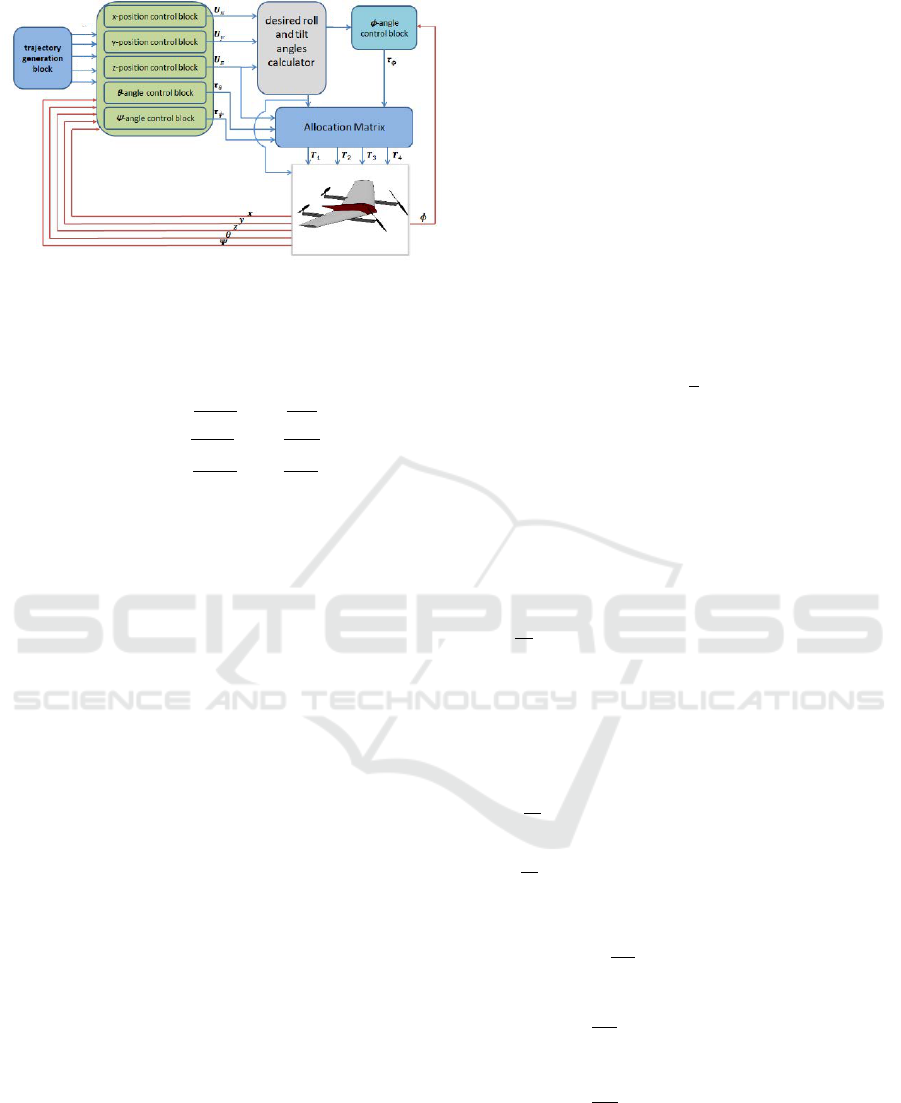
The control scheme adopted in this work is outlined
in Fig.2. Unlike conventional quadrotors our Quad-
TRUAV has an extra control input, which is the tilt
angle of the front rotors. In our control scheme, this
input is exploited to decouple the forward position
control from that of the pitch angle. The TRUAV’s
trajectory is, thus, specified by five independent vari-
ables: the 3D position (x
d
, y
d
, z
d
), as well as the pitch
and yaw angles (θ
d
, ψ
d
).
In our control scheme, the output of the forward
position controller, U
x
, is mapped to the tilt angle γ.
The loss in vertical thrust force caused by the tilting
of the front rotors is compensated for by raising the
rotation speed of these rotors such that the projection
of the generated forces on the z axis meets the control
output of the altitude controller, U
z
.
The virtual control output U
y
is mapped to the roll
angle φ in the same way as it is in a conventional mul-
tirotor. The heading angle, ψ, is also controlled like a
conventional multi-rotor. The pitch angle controller,
on the other hand, takes into account the variation in
the tilt angle of the front rotors.
To simplify the controller design, the following
assumptions are considered:
- The roll φ and pitch θ angles are small, so Euler
angle rate are approximated to the angular rates in
the body frame
˙
φ
˙
θ
˙
ψ
=
p
q
r
(23)
Modeling SMC Based Trajectory Tracking for a Tilt-Rotor Convertible UAV
99
/
"
/
x-position control block
Ux
.
</>a
desired roll
and tilt
tf>-angle
control b lock
Xa
'
u,,
"'
y-position control block
angles
generation
block
Za
8a
'l'a
Uz
calculator
</>d-yd
r
</>
z-position control block
8-angle control block
Te
'
' y
)
"'
fP.angle control block
Tip
.
Allocation Matrix
'.
'
,
\
"
,
tT1 tT2tT3tT4
"--'/
.----
\
1
"'
</>
V
........•. ...
z
A
1
"'
𝜙
∗
& 𝛾
∗
𝜙
∗
𝛾
∗
𝜓
∗
𝜃
∗
𝑧
∗
𝑦
∗
𝑥
∗
Quad-TRUAV Plant
Figure 2: Proposed Control scheme of the Quad-TRUAV.
- Given the symmetry of the Quad-TRUAV, the
term I
xz
in the inertia matrix is neglected. This
simplifies equation (12) to
¨
φ
¨
θ
¨
ψ
=
I
yy
−I
zz
I
xx
˙
θ
˙
ψ +
τ
φ
+l
I
xx
I
zz
−I
xx
I
yy
˙
φ
˙
ψ +
τ
θ
+m
I
yy
I
xx
−I
yy
I
zz
˙
φ
˙
θ +
τ
ψ
+n
I
zz
(24)
The control input vector is chosen as
U =
U
1
U
2
τ
φ
τ
θ
τ
ψ
(25)
with
U
1
= −T
1+2
sinγ − T
3+4
(26)
U
2
= T
1+2
cosγ (27)
τ
φ
= (K
ld
cosγ − l
y
sinγ)T
1−2
− l
y
T
3−4
(28)
τ
θ
= sinγl
x
T
1+2
− l
x
T
3+4
(29)
τ
ψ
= −(K
ld
sinγ + l
y
cosγ)T
1−2
+ K
ld
T
3−4
(30)
The corresponding allocation matrix is
M =
−(sθcγ+cθcφsγ) −cθcφ 0 0
0 0 (K
l d
cγ−l
y
sγ) −l
y
sγl
x
−l
x
0 0
0 0 −(K
l d
sγ+l
y
cγ) K
l d
(31)
The thrust forces are hence calculated as
T
1+2
T
3+4
T
1−2
T
3−4
= M
−1
U
z
τ
φ
τ
θ
τ
ψ
(32)
For the sake of clarity, the following intermediate
control variables are considered
U
x
= cψcθ · U
2
+ (cψsθcφ + sψsφ)U
1
(33)
U
y
= sψcθ · U
2
+ (cφsθsψ − sφcψ)U
1
(34)
U
z
= −sθU
2
+ (cφcθ)U
1
(35)
In what follows, we present the design of an SMC
controller for each variable of the Quad-TRUAV. Slid-
ing mode control belongs to the family of discontinu-
ous control systems. It is an ideal instrument for ad-
dressing the control of complex dynamic plants, such
as that of the Quad-TRUAV.
We start with the design of the roll angle con-
troller. The tracking error of the roll angle is defined
as,
e
φ
= φ
∗
− φ (36)
The corresponding sliding surface is chosen such that
σ
φ
= ˙e
φ
+ λ
φ
e
φ
(37)
with λ
φ
> 0.
This gives the following derivative for the sliding
surface:
˙
σ
φ
= ¨e
φ
+ λ
φ
˙e
φ
(38)
=
¨
φ
∗
−
¨
φ + λ
φ
(
˙
φ
∗
−
˙
φ) (39)
A Lyapunov function, V , is then chosen, such that
V =
1
2
σ
2
φ
(40)
To ensure the sliding condition we have
˙
σ
φ
= −η
φ
sign(σ
φ
) (41)
with η
φ
> 0.
By deriving the sliding surface in equation (39)
and replacing
˙
φ by its definition from equation (24),
the control input τ
φ
of the SMC controller is obtained
as
τ
φ
=
1
b
1
−a
1
˙
θ
˙
ψ − b
1
l +
¨
φ
∗
+ λ
φ
(
˙
φ
∗
−
˙
φ) + η
φ
signσ
φ
(42)
with η
φ
> 0.
Following the same steps as for the roll controller,
the control inputs for the pitch angle τ
θ
, the heading
angle τ
ψ
, and the 3D position U
z
, U
x
, and U
y
are cal-
culated as
τ
θ
=
1
b
2
−a
2
˙
φ
˙
ψ − b
2
m +
¨
θ
∗
+ λ
θ
(
˙
θ
∗
−
˙
θ) + η
θ
signσ
θ
(43)
τ
ψ
=
1
b
3
−a
3
˙
φ
˙
θ − b
3
n +
¨
ψ
∗
+ λ
ψ
(
˙
ψ
∗
−
˙
ψ) + η
ψ
signσ
ψ
(44)
U
z
= m
−g −
F
i
az
m
+ ¨z
∗
+ λ
z
(˙z
∗
− ˙z) + η
z
signσ
z
(45)
U
x
= m
−
F
i
ax
m
+ ¨x
∗
+ λ
x
( ˙x
∗
− ˙x) + η
x
signσ
x
(46)
U
y
= m
−
F
i
ay
m
+ ¨y
∗
+ λ
y
( ˙y
∗
− ˙y) + η
y
signσ
y
!
(47)
with η
θ
, η
ψ
, η
z
, η
x
and η
y
real positive
parameters.
SIMULTECH 2023 - 13th International Conference on Simulation and Modeling Methodologies, Technologies and Applications
100

Table 1: Parameters of the Zagi flying wing used in this work.
Parameter Value
Longitudinal
Coef.
Value
Lateral
Coef.
Value
m 1.56 kg CL
0
0.09167 CY
0
0
I
xx
0.1147 kg m
2
CD
0
0.01631 Cl
0
0
I
yy
0.0576 kg m
2
Cm
0
-0.02338 Cn
0
0
I
zz
0.1712 kg m
2
CL
α
3.5016 CY
β
-0.07359
I
xz
0.0015 kg m
2
CD
α
0.2108 Cl
β
-0.02854
S 0.2589 m
2
Cm
α
-0.5675 Cn
β
-0.00040
b 1.4224 m CL
q
2.8932 CY
p
0
c 0.3302 m CD
q
0 Cl
p
-0.3209
ρ 1.2682 kg/m
3
Cm
q
-1.3990 Cn
p
-0.01297
CY
r
0
Cl
r
0.03066
Cn
r
-0.00434
Figure 3: 3D trajectory followed by the Quad-TRUAV.
4 SIMULATION RESULTS AND
DISCUSSION
To validate the proposed control scheme and the asso-
ciated SMC controller, simulations are conducted on
the full non-linear model of the Quad-TRUAV. The
model considered in this work is that of the famous
Zagi flying wing (Beard and McLain, 2012). The geo-
metrical, inertial, and aerodynamic parameters of this
drone are summarised in table 1.
We consider the saturation of the four actuators to
make our model even more realistic. The saturation
is selected so that the four rotors can only provide a
lift force equal to double the drone’s weight. The tra-
jectory under consideration contains three segments.
The initial phase consists of a takeoff and ascent to
a height of 7.5 meters. During the second phase, the
drone pitches up and speeds forward until it reaches 7
m/s, which it sustains for 20 seconds. The drone then
begins to decelerate until it comes to a stop, levels out,
and begins to land.
Fig.3 depicts the 3D reference trajectory and the
trajectory followed by the drone. As the figure shows,
the proposed control scheme and associated sliding
mode controller were capable of smoothly tracking
the reference trajectory in all its phase. This solution
also ensured a smooth transition, between VTOL and
fixed wing mode.
Fig. 4a shows in more detail the temporal varia-
tion of the 3D trajectory followed by the drone and
the corresponding tracking errors. The tracking er-
rors along the x axis are much higher compared to the
y and z axes. This is due to the higher manoeuvres
that the drone makes along this axis.
Fig. 5 plots the evolution of the drone’s attitude in
terms of Euler angles. It is to note that the variations
of the pitch angle at 25 sec and 70 sec did not affect
the drone’s position despite the coupling between the
x position and pitch angle. This is achieved thanks to
the non-linearity of the SMC controller, which explic-
itly compensates for this coupling.
With regard to the control efforts, the thrust forces
generated by the four rotors are depicted in Fig. 6a.
As the drone moves forward, its wings generate more
lift and less thrust is needed to maintain its altitude.
The average value of the rotors’ thrust is about
4N in the VTOL phase. This value is decreased to
about 2.5N in the cruise flight phase. This results in
less power consumption and hence more endurance as
mentioned earlier.
The main drawback of the SMC controller is the
chattering which appears in all the control inputs.
This effect would be less pronounced in practice, be-
cause it will be filtered by the actuators’ dynamics.
Fig. 6b shows the evolution of the tilting angle.
The pitch up action, which happens at 25 sec, results
in a decrease of the tilt angle by about 70
◦
. During
the transition, the tilt angle continues to decrease to
about 60
◦
.
From these results, it is concluded that all control
inputs remain within the saturation limits we set for
them. The maximum tilt angle achieved was about
48
◦
from vertical, while its saturation was set to 60
◦
.
It is worth noting that this saturation is necessary for
the Quad-TRUAV, since a minimum component of
Modeling SMC Based Trajectory Tracking for a Tilt-Rotor Convertible UAV
101

0 10 20 30 40 50 60 70 80 90 100
Time(s)
0
50
100
150
200
X(m)
X
d
X
0 10 20 30 40 50 60 70 80 90 100
Time(s)
-1.5
-1
-0.5
0
0.5
1
Y(m)
10
-3
Y
d
Y
0 10 20 30 40 50 60 70 80 90 100
Time(s)
-8
-6
-4
-2
0
Z(m)
Z
d
Z
(a)
0 10 20 30 40 50 60 70 80 90 100
Time(s)
0
0.05
0.1
0.15
e
X
(m)
0 10 20 30 40 50 60 70 80 90 100
Time(s)
-1.5
-1
-0.5
0
0.5
1
e
Y
(m)
10
-3
0 10 20 30 40 50 60 70 80 90 100
Time(s)
-5
0
5
e
Z
(m)
10
-3
(b)
Figure 4: Trajectory tracking results: (a) desired and actual
horizontal positions and altitude; (b) corresponding track-
ing errors.
thrust on the z
b
is required to allow the control of the
pitch angle.
5 CONCLUSION
This paper dealt with the problem of trajectory track-
ing for a tilt-rotor convertible UAV. Since the drone
contains no control surfaces, only rotors were relied
on to ensure the control of its 6 DOF. A control
scheme which takes into account this particularity and
a sliding mode controller were designed to ensure tra-
jectory tracking.
0 10 20 30 40 50 60 70 80 90 100
Time(s)
-0.4
-0.2
0
0.2
0.4
(°)
d
0 10 20 30 40 50 60 70 80 90 100
Time(s)
0
5
10
(°)
d
0 10 20 30 40 50 60 70 80 90 100
Time(s)
-0.15
-0.1
-0.05
0
(°)
d
(a)
0 10 20 30 40 50 60 70 80 90 100
Time(s)
-0.5
0
0.5
e (°)
0 10 20 30 40 50 60 70 80 90 100
0
2
4
6
8
10
e (°)
10
-3
0 10 20 30 40 50 60 70 80 90 100
Time(s)
0
0.05
0.1
0.15
e (°)
(b)
Figure 5: Evolution of the drone’s attitude : (a) From top to
bottom roll, pitch, and yaw angles (b) corresponding track-
ing errors.
The proposed control scheme and associated SMC
were validated on the full non-linear model of the
drone, including all couplings and actuators satura-
tion. Simulation results were very promising. Future
works will investigate solutions for the estimation of
the aerodynamic forces and moments and the imple-
mentation of the proposed control solution on a real
plateform.
SIMULTECH 2023 - 13th International Conference on Simulation and Modeling Methodologies, Technologies and Applications
102

0 10 20 30 40 50 60 70 80 90 100
Time(s)
0
2
4
6
8
T(N)
T
1
0 10 20 30 40 50 60 70 80 90 100
Time(s)
0
2
4
6
L(N)
(a)
0 10 20 30 40 50 60 70 80 90 100
Time(s)
40
60
80
100
(°)
0 10 20 30 40 50 60 70 80 90 100
Time(s)
0
2
4
6
8
V
a
(m/s)
(b)
Figure 6: Control inputs: (a) thrust and lift forces; (b) tilt
angle and airspeed.
REFERENCES
Beard, R. W. and McLain, T. W. (2012). Small Unmanned
Aircraft Theory and Practice. Princeton University
Press.
Chen, C., Zhang, J., Wang, N., Shen, L., and Li, Y.
(2021). Conversion control of a tilt tri-rotor un-
manned aerial vehicle with modeling uncertainty. In-
ternational Journal of Advanced Robotic Systems,
18:172988142110270.
Ducard, G. J. and Allenspach, M. (2021). Review of de-
signs and flight control techniques of hybrid and con-
vertible vtol uavs. Aerospace Science and Technology,
118:107035.
Flores, G. and Lozano, R. (2013). Transition flight
control of the quad-tilting rotor convertible mav.
pages 789–794. IEEE. a nonlinear control strat-
egy based on saturations and Lyapunov design is
given¡br/¿¡br/¿stabilize the altitude z with a bounded
control input, we will use the nested saturation control
approach.
Flores, G. R., Escare
˜
no, J., Lozano, R., and Salazar, S.
(2012). Quad-tilting rotor convertible mav: Modeling
and real-time hover flight control. Journal of Intelli-
gent & Robotic Systems, 65:457–471.
Govdeli, Y., Muzaffar, S. M. B., Raj, R., Elhadidi, B., and
Kayacan, E. (2019). Unsteady aerodynamic mod-
eling and control of pusher and tilt-rotor quadplane
configurations. Aerospace Science and Technology,
94:105421.
Hegde, N. T., George, V., Nayak, C. G., and Kumar, K.
(2019). Design, dynamic modelling and control of
tilt-rotor uavs: a review. International Journal of In-
telligent Unmanned Systems, 8:143–161.
Hernandez-Garcia, R. G. and Rodriguez-Cortes, H. (2015).
Transition flight control of a cyclic tiltrotor uav based
on the gain-scheduling strategy. pages 951–956.
IEEE.
Kim, J., Kim, S., Ju, C., and Son, H. I. (2019). Unmanned
aerial vehicles in agriculture: A review of perspective
of platform, control, and applications. IEEE Access,
7:105100–105115.
Li, X., Tan, J., Liu, A., Vijayakumar, P., Kumar, N., and
Alazab, M. (2021). A novel uav-enabled data col-
lection scheme for intelligent transportation system
through uav speed control. IEEE Transactions on In-
telligent Transportation Systems, 22:2100–2110.
Papachristos, C., Alexis, K., and Tzes, A. (2012). Towards
a high-end unmanned tri-tiltrotor: design, modeling
and hover control. pages 1579–1584. IEEE.
Papachristos, C., Alexis, K., and Tzes, A. (2013). Lin-
ear quadratic optimal trajectory-tracking control of a
longitudinal thrust vectoring-enabled unmanned tri-
tiltrotor. IECON Proceedings (Industrial Electronics
Conference), pages 4174–4179.
Phung, D.-K. and Morin, P. (2014). Control of a new con-
vertible uav with a minimal sensor suite. volume
2015-Febru, pages 229–235. IEEE.
Prouty, R. W. (2002). Helicopter Performance, Stability and
Control.
Saeed, A. S., Younes, A. B., Cai, C., and Cai, G. (2018). A
survey of hybrid unmanned aerial vehicles. Progress
in Aerospace Sciences, 98:91–105.
Saeed, A. S., Younes, A. B., Islam, S., Dias, J., Seneviratne,
L., and Cai, G. (2015). A review on the platform de-
sign, dynamic modeling and control of hybrid uavs.
pages 806–815. IEEE.
Shakhatreh, H., Sawalmeh, A. H., Al-Fuqaha, A., Dou, Z.,
Almaita, E., Khalil, I., Othman, N. S., Khreishah, A.,
and Guizani, M. (2019). Unmanned aerial vehicles
(uavs): A survey on civil applications and key re-
search challenges. IEEE Access, 7:48572–48634.
Su, J., Su, C., Xu, S., and Yang, X. (2019). A multi-
body model of tilt-rotor aircraft based on kane’s
method. International Journal of Aerospace Engi-
neering, 2019:1–10.
Ta, D. A., Fantoni, I., and Lozano, R. (2012). Modeling
and control of a tilt tri-rotor airplane. pages 131–136.
IEEE. This paper is used to cite the woks used for
controlling TRUAV.
Modeling SMC Based Trajectory Tracking for a Tilt-Rotor Convertible UAV
103
