
Work in Progress: Extending Virtual Prototypes of Microprocessor
Architectures with Accuracy Tracing
Johannes Kliemt
a
and Dietmar Fey
b
1
Chair of Computer Science 3 (Computer Architecture), Friedrich-Alexander Universitaet Erlangen-Nuernberg,
Martensstr. 3, Erlangen, Germany
Keywords:
vHIL, Virtual Prototypes.
Abstract:
Virtual Prototypes of mi croprocessor architectures (VPs) extensively support the software development pro-
cess with the ability to build virtual Hardware in the Loop (vHIL) test benches. A physical hardware is not
necessary since the VP is al so a functional simulation model, although with reduced accuracy. The actual
deviation to the physical hardware in the time domain is mostly unspecified and dependent on the executed
application software. This leads to issues when used in the development of software with real time require-
ments. The authors propose a new way of determining this inaccuracy via a trace unit integrated into the VP.
Accuracy is now determined for each application software on the fl y taking its individual paths through the
model and not by a unrelated general set of accuracy benchmarks. A more reliable statement on the later
temporal behavior on the physical hardware can therefore be given.
1 INTRODUCTION
Functional simulation models of different micropro-
cessors architectures called Virtual Prototypes (VPs)
are already actively used in science for many y ears
now. They recently became also popular for industrial
usage. Together with Synopsys, Infineon relea sed the
third generation of their Aurix microcontroller fam-
ily as VP back in 2020 for their automotive Tire
1 and OEM customers (Sim one Sou z a, 2020), two
years before physical chip examples became avail-
able. VPs can be used to realize so called virtual
Hardware in Loop test benches where in contrast
to normal HIL simulations also the actual ha rdware
sensing and controlling the plant model is simulated
(Reitz et al., 2020). Such a vHIL was d eveloped by
the authors in cooperation with a widely known car
manufacturer for evaluating purposes with the second
generation Aurix microcontroller and a n electric en-
gine as plant model. During the project, the question
on the accuracy of the used Aurix TC3xx VP and on
the reliability of its simulation results came up. Find-
ing an answer to this question was difficult, leading to
a new idea for approaching an d handling inaccura cy
in VPs. This concept will be pro posed in this position
a
https://orcid.org/0009-0002-6515-4724
b
https://orcid.org/0000-0002-6077-4732
paper.
2 OVERVIEW
A exemplary accuracy measurement on the TC39x
VP for motivation of the proposed idea will be pre-
sented in section 3, Afterwards, a short overview
of the standard modeling technique in VPs for sys-
tem buses is given in section 4 explaining a possible
source of the encountered inaccuracy. Co nsequences
for VP users and an idea for mitigation with automatic
inaccuracy tracing is described in section 5. A sum-
mary and a outlook on futur e work in section 6 con -
cludes the paper.
3 ACCURACY OF VPS
In general a VP is to 100% accurate, if its simulation
produces the exact same result as its counterpart, the
physical hardware. This includes th e functional as-
pect e.g. an instruction of a compute core produces
the same result as well as the non functional aspect,
e.g. the result of the instruction is available at the
same point in time on both platforms.
Determining the total accuracy of a VP is a non
trivial and complicated task. Different parts of the VP
Kliemt, J. and Fey, D.
Work in Progress: Extending Virtual Prototypes of Microprocessor Architectures with Accuracy Tracing.
DOI: 10.5220/0012131800003546
In Proceedings of the 13th International Conference on Simulation and Modeling Methodologies, Technologies and Applications (SIMULTECH 2023), pages 409-416
ISBN: 978-989-758-668-2; ISSN: 2184-2841
Copyright
c
2023 by SCITEPRESS – Science and Technology Publications, Lda. Under CC license (CC BY-NC-ND 4.0)
409
might be modeled with different accuracy and simu-
lation speed goals in mind. These two goals are in-
versely correlated to each other. Usually the differ-
ent com ponents are modeled by different developer
teams as well, inc reasing the chance for deviation in
the mo deled ac curacy. So it can occur that the most
frequently used com putational units (on the TC3xx
architecture the TriCores) and their direct memory pe-
ripheral devices are simulated with near ha rdware ac-
curacy whereas other peripherals show significant in-
accuracies.
The achievable accuracy depends therefore on the
concrete software application running on the VP, with
its individual paths thr ough the system. During the
work with the developed vHIL some serious time de-
viation at tran sactions over the Aurix TC39x’s central
SRI Bus in the VP had b e en observed in comparison
with the physical hardware. For a more precise and
qualified statement an accuracy benchmark of the SRI
Bus with usage of the Aurix Direct Memory Access
(DMA) module was deployed. This benchmark and
the evaluation of its results will be described in the
following section.
3.1 Accuracy Benchmark Setup
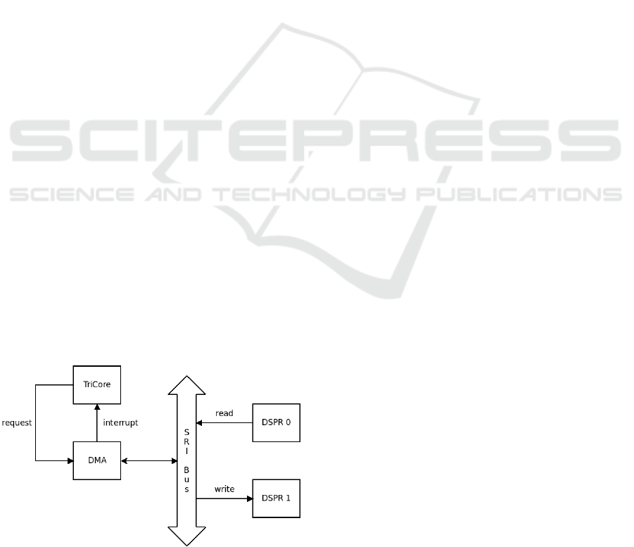
The benchm ark consists of a series of DMA transfers
between two Data Scratch-Pad RAMs (DSPRs) with
an increasing number of individual moves per DMA
transfer (1 to 64). A move is composed of readin g
one 64-Bit data word (SRI Bus data width) fr om the
first DSPR and writing it to the second one. This test
case is not d etached from real world applications as
its function a l aspect can be found in use cases like
fetching ADC conversion results or piplined data pro-
cessing with multiple TriCores. Figure 1 depicts the
control and data flow of the benchmark setup, which
was implemented with a simple C program. The cor-
respond ing binar y was then executed bo th on the VP
and on the physical ha rdware.
Figure 1: SRI Bus accuracy benchmark setup.
The DMA modu le was used as it has less hard-
ware features possible affecting the measurement of
the actual bus transfer times. One could also use one
of the TriCores for transferring data between the two
memories in this b e nchmark, but their internal archi-
tecture ( Load-Stor e pipeline a nd Store Buffers) will
hinder a reproduc ible and pre cise measurement.
Time was measured via the built-in performance
counters in the TriCore orch estrating the DMA op-
eration. This is the simplest but still precise time
measuring method, requiring no addition al external
adaption effort neither to the VP nor to the physical
hardware. A time stamp from the clock counter regis-
ter was read immediately after initiating a DMA SW
request and at the beginning of the Interrupt Service
Routine (ISR) following the completed DMA trans-
fer, measuring therefore the number of ela psed clock
cycles dur ing the DMA operation. The TriCore is
idling via Nop instructions during this tim e . For nar-
rowing down the mea surement result as c lose as pos-
sible to the actual bus transactions, a second measure-
ment was done, triggering the DMA ISR m anually by
SW. Sub tracting this time from the first measurement
results in the active time of DMA Move Engin e as
the only measuremen t overhead over the actual SRI
Bus tra nsfer times. A more accurate way of measur-
ing the actual bus transfers on the physical hardware
is not possible without special and costly (off-chip)
trace devices.
The measurement for each DMA transfer was ex-
ecuted 100 times and rounded to the next in teger to
avoid any disturbance introduced by the instruction
cache of the TriCore executing the measure ment.
The Aurix TC3xx VP can be con figured before
simulation start regarding the simulated accur a cy. To
avoid any inaccuracy in the VP due to temporal de-
coupling between the TriCore (with its clock counter)
and the DMA module, the quantum size was set to
one clock cycle. The quantum size defines how long
different components of the VP can run ahead of each
other in simula tion time before resy nchronizing with
the rest of the system. This optimization sacr ifices
accuracy f or simulation speed and would distort the
accuracy measur ement. Setting it to one clock cycle
for the TriCore results in an immediate reaction on th e
DMA in te rrupt as the physical hard ware does.
There might still some inaccuracy in the actual im-
plementation of the TriCore performa nce counters in
the VP, delivering a wrong number of elapsed clock
cycles in the measurement. To encounter that, the
measurement setup from above was repeated using
now a more complex and elaborate way for determin-
ing the timestamp values. The actual point in real time
at the two time stamps had to be detected. For the VP,
SIMULTECH 2023 - 13th International Conference on Simulation and Modeling Methodologies, Technologies and Applications
410

this becomes a trivial task by attaching callback func-
tions to the relevant events. They rep ort the current
point in sim ulated time when their events w ere trig-
gered. These are the star t of the actual write to the
DMA modules con trol register initiating a SW trig-
gered DMA transfer and the TriCore program counter
register changing to the first ad dress of the DMA ISR.
On the physical hardware one has to use the On-
Chip Debug System (OCDS) module of the TC3 9x
architecture with its (in relationship to the V P) limited
tracing cap a bilities. For avoiding a high cost Lauter-
bach tracer h ardware, the free of charge Infineon
Multi-Core Debug Solution (MCDS) Trace Viewer
software was used for capturing the relevant tim e in-
formation. The time of occ urrence of the mentioned
events from above are stored to a special trace m em-
ory inside the Aurix TC39x chip. Its size is limited,
so the com plete measurement run had to be d ivided
into several steps.
For all measure ments, the Synopsys TC39xB
v2.4.0 VDK was used as VP and a Infineon
KIT
A2G TC397 5V TRB BD-Step Starter Kit for
its physical counter part. The clock of the TriCore ex-
ecuting the be nchmark was configured on both plat-
forms to 300 MHz a s well as the clock for the SRI
Bus. The D MA module runs internally with its maxi-
mum available clock frequen cy of 100 MHz.
3.2 Measurement Results
Figure 2 shows the total me a sured time in clock cy-
cles fo r each DMA transf er on the VP (blue bars) and
on the physical hardware (orange bars) for different
number of m oves per DMA transfer.
Figure 2: Measured time per DMA transfer on VP and phys-
ical hardware.
For a better view on the actual deviation, figure
3 plots the times per individual move for each DMA
transfer. T he numbe rs are the results of dividing the
total numbers of clock cycles per DMA transfer from
figure 2 by the number of actual DMA moves mar ked
on the x-axis.
The asy mptotic approach in both curves suggests
Figure 3: Measured time per DMA move on VP and physi-
cal Hardware.
that there is is still a overhead in the measurement due
to the initial internal setup time of the DMA module
for each new transfer. This overhead becomes m ore
and more negligible with increasing number of D MA
moves. Therefore the two curves le a d to the actual
DMA data transfer time s over the SRI Bus. It can
be seen, that each DMA move consisting of one read
an on e wr ite transaction over the SRI Bus takes 15
clock cycles on the physical har dware and 40 on the
VP resulting in an overestimation of the VP by 166%.
The actual intern a l DMA setup time can be deter-
mined from the measurement results as well. Table
1 shows exemplary the actual measur e d clock cycles
depicted in figure 2 for DMA transfer s from 1 to 5
moves per transfer.
Table 1: Measured number of clock cycles for DMA trans-
fers with different number of moves.
# moves 1 2 3 4 5
vp 42 82 122 162 202
hw 24 39 54 69 84
Subtracting 2 respectively 9 clock cycles and di-
viding by the number of moves per DMA transfer
leads exactly to the 40 and respectively 15 clock cy-
cles the curves in figure 3 approach. The internal
DMA setup time for each new transfe r is therefore 9
clock cycles on the physical hardware. The VP mod-
els it with only 2 clock cycles underestimating the ac-
tual tim e by 77%.
3.3 Measurement Validation
Figure 4 plots the result of the same measurement
setup from section 3.2 done utilizing now re a ltime
time stamp values provided by the MCDS tracing
module for the physical hardware and the elapsed
simulated time for the VP. For better comparability,
the measured time s per move in each DMA transfer
depicted on the y-axis have already been converted to
clock cycles (through division by the clock period of
10
3
ns).
Work in Progress: Extending Virtual Prototypes of Microprocessor Architectures with Accuracy Tracing
411

Figure 4: Measured time per DMA move on VP and physi-
cal hardware with MCDS tracing.
The time of one DMA move over the SRI Bus
approa c hes 15 clock cycles in the physical hardware
(orange curve) and 40 clo ck cycles in the VP (blue
curve). These are the exact same number of c lock cy-
cles determined with the first measur ement method.
This less complicated time mea surement method of
counting the nu mber of elapsed c lock cycles o n the
TriCore and its results are therfore validated.
3.4 Actual Bus Transfer Times
The results from the last two sections do not reflect the
individual data transfer times on the SRI Bus. T hey
also include the additional operation time of the DMA
model initiating th e bus transfers and caching the read
data from the source memory befo re it is wr itten via a
second SRI Bus transfer to the target memory. Due to
the high insight offered by the VP, the actual starting
and stoppin g times of the modeled bus transactions
are available. Read access is mod eled with 30 ns and
the write access with 37 ns adding up to 67 ns SRI
Bus time for one DMA move.
This times cannot be deter mined b y me asurement
in the physical hardware. The m easured time for one
complete DMA data move extracted from the MCDS
trace generated in section 3.3 varies b e tween 40 ns
and 55 ns. This is in th e best ca se still 12 ns less
than the actual bus time modeled in the VP. An in-
sufficient timing model of the SRI Bus in th e TC39x
VP is therefore confirmed a second time. The exact
source of this inaccuracy is indeterminable, since the
Synopsys TC39xB v2.4.0 VDK is clo sed sou rce.
Documentation of the V P sh ows that the Transac-
tion Level Mo deling (TLM 2.0) standard was used for
modeling of all system buses. An overview over this
modeling tech nique with its achievable accuracy will
be given in the next section. Additionally, a possible
explanation for the measured inaccuracy on the SRI
Bus model of th e TC39x VP will b e pr ovided.
4 TLM BUS MODELING
With the TLM bus modeling technique, all address,
data and control signal lines of a bus are abstracted
away through function calls betwe e n the mode ls of
the bus ma ster s and slaves. Addresses and data are
packed into a so called generic payload object and
only a pointe r to that object is transmitted as C++
function argument between bus participants. A sec-
ond argume nt provides information to the current
phase of the transaction. The TLM 2.0 language ref-
erence man ual ((OSCI), 2009) describes two coding
styles, namely ”Loosely Timed” (LT) and ”Appro x-
imately Timed” (AT) weakly related to different ac-
curacy levels. AT is generally considered mo re accu-
rate than LT, but the concrete accuracy difference is
neither defined n or enforced. This also holds for the
assignment of bo th approaches to a specific accuracy
level in the in te rval from cycle accurate to untimed.
Cycle accurate (CA) means the VP is as accu-
rate as its Register Transfer Level model. On this
level of abstraction, th e architecture is described in
form of logic between register (he nce Register Trans-
fer Level) operating on system clock cycles as time
base. Such a RTL model is also the starting point
for chip manufacturer developing physical hardware.
The aptness of TLM 2.0 for cycle accurate bus mod-
els achieving a speedup of at least one order of magni-
tude over RTL models was shown by (G¨unzel, 2011).
To do so, the rules for the AT coding style had do
be modified and extend ed. Only the relevant cycles
correspo nding to a phase transition in the modeled on
chip bus protocol from the RTL model are then sim-
ulated, abstracting away from for a pure fu nctional
simulation unnecessary clock cycles. Those a re wait-
ing cycles for address or data lines becoming valid
or for the ma ster or slave becom ing ready, wh ic h can
not be skipped inside a RTL model. An example for
a 2 beat write burst in a pseudo AXI proto c ol is de-
picted in figure 6 where the relevant clock cycles from
the corresp onding RTL simulation in figur e 5 are not
simulated. The (A)W
WALID signals indicate a valid
write address or data when high, the (A)W READY
the time, when the slave is ready for a new address or
new data. T he address and data lanes of the bus are
not shown here.
In clock cycle 5 neither the master nor the slave
is ready for the transmission of the secon d burst beat,
in cycle 6 and 7 the data to be transferred is not valid
yet. The doted vertical lines in figure 6 mark the cy-
cles with r elevant phase transitions (control signals
becoming high). They are simulated by executing
a f unction call transmitting the relevant information
from the master to slave on the bus (fw()) and vice
SIMULTECH 2023 - 13th International Conference on Simulation and Modeling Methodologies, Technologies and Applications
412

Figure 5: Burst write over pseudo AXI Bus - RTL model.
versa (bw()). At the transmission of the second data
beat in clock cycle 8, the slave is already ready f or the
transmission (signal W READY is high ) so no back-
wards call is necessary.
Figure 6: B urst write over pseudo AXI Bus - T LM CA
model.
The TLM 2.0 AT coding style defines two basic
phases, one for address and one f or the data exchange
and a corresponding set of r ules. Although it is possi-
ble to define additional phases, a repetition o f a phase
is not supported. The alternative of defining num-
bered burst beat phases increases simulation overhead
and is only possible for bus protocols with a prede-
fined n umber of burst beats (G¨unzel, 2011). There-
fore the multiple data transm issions inside a burst
transfer have to b e mo deled with one data phase only
approximating a ny delay between each da ta beat. Fig-
ure 7 locates this source of inacc uracy with a question
mark.
In clock cycle 3 at the star t of the data phase, the
bus master has to anticipate how many clock cycles
his data for the second write b e at will n ot be valid in
the future. Only the clock cycles marked with a ver-
tical dotted line are simulated via forward (fw() ) and
backward (bw()) function ca lls analogous to the TLM
cycle accur ate case. Note that the back ward function
call at clock cycle 8 in figure 7 finishing the data phase
can also occur a few clock cycles fewer or later due
Figure 7: Burst write over pseudo AXI Bus - TLM AT
model.
to the above d e scribed inaccuracy. If the data valid
delay is alread y k nown at clock cycle 3, the TLM AT
model can be indeed cycle accurate, too. Th e in sec-
tion 3 measured inaccuracy on SRI Bus transactions
inside Aurix TC39x VP comes very likely from badly
modeled address and data phases with the TLM AT
coding style.
With the TLM 2.0 LT coding sty le the abstrac-
tion increases one step, leaving only one phase for the
whole bus transaction. This inc reases the possibili-
ties for inaccuracy once again due to additio nal ab-
straction from the address phase. Figure 8 depicts the
example transaction from above mode le d in the LT
style.
Figure 8: Burst write over pseudo AXI Bus - TLM LT
model.
It co nsists of only one blocking transport (bt())
function c all from th e master to the slave starting at
the first dotted vertical line and returning at the sec-
ond one. Note that also here the return of the function
call modeling the whole bus write transfer c an occur
fewer or later due to the time abstraction of the LT
coding style.
Work in Progress: Extending Virtual Prototypes of Microprocessor Architectures with Accuracy Tracing
413

5 HANDLING INACCURACY IN
VPS
As described in (Synopsys, 20 13) VPs a re not a re-
placement fo r a c tual HIL testin g but provide aid in
the different stages of the V-cycle SW development
model. With this in mind, one might argue, tha t a
time inaccuracy of a few clock cycle as exemplary
measured in section 3.2 does not make a VP func-
tional incorrect and unusable for SW with real time
requirements. However, for those SW a pplications
timeliness of tasks is an ad ditional functional pro perty
defining correctness. This rises the question, whethe r
inaccuracy due to abstra ction in the modeling makes
VPs still usab le here. In case of just the pure func-
tional aspect of the individual task inside the software
the answer is a definite yes. Realizing event chains
with different hardware and software modules (e.g.
ADC input sampling → DMA data transfer → Core
calculating new PWM width → PWM mod ule output)
will definitely profit from the numerous advantages a
VP offers. The actual challenge here is ge tting the
overall timing of an event chain and the timing be-
tween its different components right. Typically th ere
is a pe riodic deadline, where new o utput values have
to be available for the whole rea l time system to work
on properly.
In the best case, all modeled components inside
a VP have a positive time inaccuracy compared to
the phy sical hardware, giving tasks a gre ater slack on
their deadlines on the latter one. However, if this pos-
itive time inaccuracy is to great, SW developers might
encounter task s not holding their deadlines only in
the VP. This will result in un necessary ch a nges to the
overall software design. In the exact opposite c ase
the designed SW systems performs correct on the VP,
but produces timing issues o n the physical hardware.
These issues cann ot be detected and located insde the
VP and require expensive testing and debugging on
the physical hardware.
All these problem cases could be dealt with at
least to a certain amount o f confidence if the total
inaccuracy inside the VP is known and always pos-
itive (task runtimes on VP not faster than on physical
hardware). This is in most times not possible, since
accuracy of VPs is usually deter mined by running a
(high) number of benchmarks comparing there execu-
tion time b e tween the VP and the corresponding phy s-
ical hardware. An examples is the Embench Bench-
mark Suit
1
that was used by (Herdt et a l., 2020) to
evaluate the accuracy of their VP mod eling the SiFive
HiFive1 architecture. Each benchmark was deployed
1
https://www. embench.org/
on the VP and then compared to the execution time
on the open source RTL model of the corresp onding
SiFive HiFive1 board. The reported accuracy varies
depending on the actual benchmark from -1 0.9% to
13.5% c lock cycles (Herd t et al., 2020).
A second example is the GVSoC VP
(Bruschi et al., 2021) which acts as a VP fo r the
whole PULP processor platform
2
. The achieved
average ac curacy of 10% is acceptable for a VP
designed for Design Space Exploration. However,
accuracy was evaluated only with one complex test-
case (MobileNet V1 convolutional neural network).
A general reliable statement on the VPs accuracy
with this evaluation approach is not possible. As al-
ready mentioned in section 3, the accuracy highly
depends on the p aths that are individually followed
through the whole system by an application software.
For reliable app roximations by the VP on the physi-
cal hardware, this accuracy comp arison has to be re-
peated for each individual software application. Even
worse, this comparison is necessary after each major
change of the software in its development process.
To counter this problem the authors propose a
modified approach for determining (in-) a ccuracy in
VPs in the next section.
5.1 Proposed Solution
The key idea is to automatically determine the indi-
vidually encountered inaccuracy and report it to the
user of the VP. All time deviations in each modeled
component have to be determined by the VP devel-
oper and than included in its source code for trac-
ing. Costly accuracy be nchmarks done by every VP
user for its ind ividual SW application can therefore be
completely avoided.
For buses, this trace adds up the inaccuracy for
each executed transaction over all involved bus com-
ponen ts (e.g. arbiter) between master and slave. All
sources of inaccuracy have to be located and quanti-
fied at least in well defined intervals. For the localiza-
tion of possible inaccuracy in bus modeling via TLM,
a short overview was already given in section 4. The
challengin g p a rt is the qu antification of the modeling
error. There are two kinds of sources for these errors,
namely static and a dynamic ones.
Static erro rs occu r ind ependen tly of any dynamic
events on the bus peripherals. An example is a archi-
tectural constraint in the master that introduce a static
number of wait cycles, b e fore the data for a new burst
beat can be outputted on th e bus. A modeling error
does not need any tracing here, since a refinement of
2
https://pulp-platform.org/
SIMULTECH 2023 - 13th International Conference on Simulation and Modeling Methodologies, Technologies and Applications
414
the TLM model is trivial and comes with no simula-
tion overhead. T he master computes the num ber of
burst beats multiplied by the static delay time and no-
tifies the slave with the forward call (e.g see clock
cycle 3 in figure 7). The slave can account for that
delay by delaying his backward call according ly. If a
refinement is not possible (e.g. due to a closed source
VP) tracing the resulting static inaccura cy for a bus
transfer is a suitable alternative. However, if at the
begin of the data phase the data delay is not known
yet for each burst beat, inaccuracy will occur in the
TLM transaction. To reflect tha t dynamically caused
inaccuracy in the proposed trace methodology, it logs
the minimum and maximum possible delays for that
transaction. T hese delays have to be (analytically) de-
termined once for each m aster and each slave attached
to the bus. Doing that for a specific VP as proof of
concept will be up to future work.
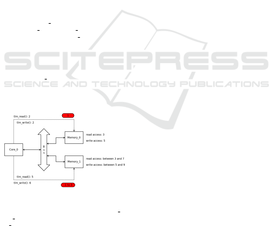
For better explanation of the pr oposed accuracy
tracing methodology, a minimal hypothetical exam-
ple hardware is depicted in figure 9. It consists of a
compute core (Core
0), that is connected to two mem-
ories (Memory 0 and M emory 1) via a common bus.
Let the access time for Mem ory
0 be constant 3 clock
cycles for a read operation and 5 clock cycles for a
write operation. Both access typ es have been some-
how mod eled with a 2 clock cycle TLM transaction
in the c orresponding VP, see dotted arrow in figure
9. The same was done with the TLM modeled ac-
cesses to Memory
1, this time with 5 and respectively
6 clock cycles. Its physical c ounterp a rt has a dynamic
access time for read operations between 3 and 7 clock
cycles and for write operations between 5 and 9 clock
cycles.
Figure 9: Minimal hypothetical example hardware for ac-
curacy tracing of TLM modeled buses.
Consider now a load operation from Memory
0 by
Core
0, that is followed by a store operation to Mem-
ory 1. This will take 3 + 5 to 9 clock cycles on the
physical hardware. The TLM transactions inside the
VP approximate it by 2 and 6 cloc k cycles. Deploy-
ing a time measurement in the VP results in a time
of 8 clock cycles for the whole load store sequenc e .
However, this measurement result contains a hidden
inaccuracy of 1 to 4 clock cycles. To get hold of this,
the accuracy trace can be consulted. It log ged for the
TLM read transaction a deviation of 1 clock cycle
and for the write transaction a minimal deviation of
-1 clock cycle and a maximal deviation of 3 (see red
ovals in figure 9). With this additional information,
the actual execution time of the load store sequence
on the physical hardware can now be de te rmined in
at least a certain time interval by measurements in the
VP. A software developer, that uses latter one for time
performance evaluation, has therefore now a more re-
liable decision base for making changes to his code.
6 SUMMARY & FUTURE WORK
This position paper pr oposed the so far not yet imple-
mented idea of VPs, tracing the their individual inac-
curacy as a n additional simulation output. The idea
was motivated via an exemplary accuracy measure-
ment d one on a in dustrial grade VP of the Infineon
TC39x microcontroller family. A short overview of
the bus modeling technique with TLM 2.0 and its
achievable accuracy was given, narrowing down the
most likely reason for the detected deviations. The
last section of this paper described shortly the con-
sequences for VP users and a way for mitigation by
introdu cing the idea of VPs repo rting the individually
encountered overall inaccuracy to its user.
Future work will be the actual implementation
of the proposed idea, expanding this concept from
bus modeling also to the other impo rtant compo-
nents inside a VP. Examples are central compute units
with their piplined instruction execution and caches,
requirin g additional modeling techniques with their
specific sources of inaccuracy.
REFERENCES
Bruschi, N. , Haugou, G., Tagliavini, G., Conti, F., Benini,
L., and Rossi, D. (2021). Gvsoc: A highly config-
urable, fast and accurate full-platform simulator for
risc-v based iot processors. In 2021 IEEE 39th In-
ternational Conference on Computer Design (ICCD),
pages 409–416.
G¨unzel, R. (2011). Taktgenaue Bus-Simulation mit der
Transaction-Level-Modellierung. PhD t hesis.
Herdt, V., Große, D ., and Drechsler, R. (2020). Fast and
accurate performance evaluation for risc-v using vir-
tual prototypes. In 2020 Design, Automation & Test in
Europe Conference & Exhibition (DATE), pages 618–
621.
Work in Progress: Extending Virtual Prototypes of Microprocessor Architectures with Accuracy Tracing
415

(OSCI), O. S. I. (2009). Osci tlm-2.0 language refer-
ence manual. https://www.accellera.org/images/
downloads/standards/systemc/TLM
2 0 LRM.pdf.
accessed 04.04.2023.
Reitz, J., Gugenheimer, A., and Roßmann, J. (2020). Virtual
hardware in the loop: Hybrid simulation of dynamic
systems with a virtualization platform. In 2020 Winter
Simulation Conference (WSC), pages 1027–1038.
Simone Souza, Synopsys, I. (2020). Synopsys ex-
pands portfolio of automotive vdks with support
for infineon’s aurix tc4xx 32-bit microcontroller
family. https://news.synopsys.com/2020-10-27-
Synopsys-Expands-Portfolio-of-Automotive-VDKs-
with-Support-for-Infineons-AURIX-TC4xx-32-bit-
Microcontroller-Family. accessed 04.04.2023.
Synopsys (2013). Virtual hardware “in-the-loop”: Earlier
testing for automotive applications. https://www.
synopsys.com/cgi-bin/ proto/pdfdla/docsdl/virtual
hardware wp.pdf?file=virtual hardware wp.pdf.
accessed 30.03.2023.
SIMULTECH 2023 - 13th International Conference on Simulation and Modeling Methodologies, Technologies and Applications
416
